What is Ohm's Law?


what is ohm's law

Ohm’s Law defines the essential link between voltage, current, and resistance in electrical circuits. It provides the foundation for circuit design, accurate troubleshooting, and safe operation in both AC and DC systems, making it a core principle of electrical engineering.


What is Ohm’s Law?

Ohm’s Law is a fundamental principle of electrical engineering and physics, describing how voltage, current, and resistance interact in any circuit.

✅ Defines the relationship between voltage, current, and resistance

✅ Provides formulas for design, safety, and troubleshooting

✅ Essential for understanding both AC and DC circuits

When asking what is Ohm’s Law, it is useful to compare it with other fundamental rules like Kirchhoff’s Law and Ampere’s Law, which expand circuit analysis beyond a single equation.


What is Ohm's Law as a Fundamental Principle

Ohm's Law is a fundamental principle in electrical engineering and physics, describing the relationship between voltage, current, and resistance in electrical circuits. Engineers can design safe and efficient electrical circuits by understanding this principle, while technicians can troubleshoot and repair faulty circuits. The applications are numerous, from designing and selecting circuit components to troubleshooting and identifying defective components. Understanding Ohm's Law is essential for anyone working with electrical circuits and systems.


Who was Georg Ohm?

Georg Simon Ohm, born in 1789 in Erlangen, Germany, was a physicist and mathematician who sought to explain the nature of electricity. In 1827, he published The Galvanic Circuit Investigated Mathematically, a groundbreaking work that defined the proportional relationship between voltage, current, and resistance. Though his research was initially dismissed, it later became recognized as one of the cornerstones of modern electrical science.

His work introduced key concepts such as electrical resistance and conductors, and his law became fundamental to circuit design and analysis. The scientific community honored his contribution by naming the unit of resistance — the ohm (Ω) — after him. Today, every student and professional who studies electricity carries his legacy forward.

Georg Simon Ohm


What is Ohm’s Law Formula

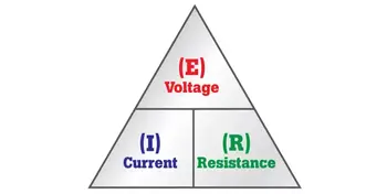
At the heart of the law is a simple but powerful equation:

V = I × R

  • V is voltage, measured in volts (V)

  • I is current, measured in amperes (A)

  • R is resistance, measured in ohms (Ω)

Rearranging the formula gives I = V/R and R = V/I, making it possible to solve for any unknown value when the other two are known. This flexibility allows engineers to calculate required resistor values, predict circuit performance, and confirm safe operating conditions.

In both DC and AC systems, the law provides the same basic relationship. In AC, where current and voltage vary with time, resistance is replaced with impedance, but the proportional link remains the same.

The Ohm’s Law equation explains how the amount of electric current flowing through a circuit depends on the applied voltage and resistance. Current is directly proportional to voltage and inversely proportional to resistance, illustrating how electrical charge flows under various conditions. To maintain consistency in calculations, the law employs standard units: volts (V) for voltage, amperes (A) for current, and ohms (Ω) for resistance. Since Ohm’s Law formula defines the relationship between these values, it directly connects to related concepts such as electrical resistance and voltage.


Understanding the Formula

The strength of Ohm’s Law lies in its versatility. With just two known values, the third can be calculated, turning raw measurements into useful information. For an engineer, this might mean calculating the resistor needed to protect a sensitive device. For a technician, it may indicate whether a failing motor is caused by excess resistance or a low supply voltage.


How the Formula Works in Practice

Consider a simple example: a 12-volt battery connected to a 6-ohm resistor. Using the law, the current is I = V/R = 12 ÷ 6 = 2 amperes. If resistance doubles, the current halves. If the voltage increases, the current rises proportionally.

In practical terms, Ohm’s Law is used to:

  • calculate resistor values in electronic circuits,

  • verify safe current levels in wiring and equipment,

  • determine whether industrial loads are drawing excessive power,

  • troubleshoot faults by comparing measured and expected values.

Each of these tasks depends on the same simple equation first described nearly two centuries ago. Applying Ohm’s Law often involves calculating current in DC circuits and comparing it with alternating current systems, where impedance replaces simple resistance.


Modern Applications of Ohm’s Law

Far from being outdated, Ohm’s Law remains central to modern technology. In electronics, it ensures safe current levels in devices from smartphones to medical equipment. In renewable energy, it governs the design and balance of solar panels and wind turbines. In automotive and electric vehicle systems, battery management and charging depend on accurate application of the law. Even in telecommunications, it ensures signals travel efficiently across cables and transmission lines. In power engineering, Ohm’s Law works alongside Watts Law and power factor to determine efficiency, energy use, and safe operating conditions.

These examples demonstrate that the law is not a relic of early science but an active tool guiding the design and operation of contemporary systems.


Resistance, Conductivity, and Real-World Limits

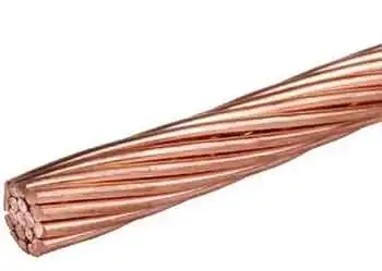
Resistance is a material’s opposition to current flow, while conductivity — its inverse — describes how freely charge moves. Conductors, such as copper and aluminum, are prized for their high conductivity, while insulators, like rubber and glass, prevent unwanted current flow.

In reality, resistance can change with temperature, pressure, and frequency, making some devices nonlinear. Semiconductors, diodes, and transistors do not always follow Ohm’s Law precisely. In AC systems, resistance expands to impedance, which also considers inductance and capacitance. Despite these complexities, the proportional relationship between voltage and current remains an essential approximation for analysis and design. Exploring basic electricity and related principles of electricity and magnetism shows why Ohm’s Law remains a cornerstone of both theoretical study and practical engineering.


Frequently Asked Questions


What is an example of Ohm's Law?

A simple example in action is a circuit consisting of a battery, a resistor, and a light bulb. If the voltage supplied by the battery increases, the current flowing through the circuit will also increase, causing the light bulb to glow brighter. Conversely, if the resistance of the circuit is increased by adding another resistor, the current flowing through the circuit will decrease, causing the light bulb to dim.


What are the three formulas in Ohm's Law?

The three formulas are I = V/R, V = IR, and R = V/I. These formulas can solve a wide range of problems involving electrical circuits.


Does Ohm’s Law apply to all electrical devices?

Not always. Devices such as diodes and transistors are nonlinear, meaning their resistance changes with operating conditions. In these cases, Ohm’s Law provides only an approximation.

When asking What is Ohm’s Law, it becomes clear that it is far more than a formula. It is the framework that makes electricity predictable and manageable. By linking voltage, current, and resistance, it offers a universal foundation for design, troubleshooting, and innovation. From the earliest experiments to today’s electronics and power grids, Georg Ohm’s insight remains as relevant as ever.

Related News

What is an Ampere?

An ampere is the standard unit of electric current in the International System of Units (SI). It measures the flow of electric charge in a circuit, with one ampere equal to one coulomb of charge passing through a point per second.


What is an Ampere?

The ampere (A) is one of several units used to measure the electromagnetic force between straight, parallel conductors carrying electric current.

✅ Measures electric current or flow of electric charge per second

✅ Defined as one coulomb of charge per second in a conductor

✅ Essential in circuit design, safety, and load calculations


Scientific Definition and Formula

The ampere is defined by the formula:

  • V is voltage in volts

  • R is resistance in ohms

  • I is current in amperes

When you explore Ohm’s Law, you'll learn how voltage and resistance influence current using the formula I = V / R.


Safety Considerations

Electric current levels and their effects on the human body:

  • 1 mA: barely perceptible

  • 5–10 mA: painful shock

  • 50 mA: can cause breathing difficulty

  • 100 mA: potentially fatal if it passes through the chest

Even small currents, if applied in the wrong way, can be dangerous, especially in wet conditions.


Applications of Amperes

  • Power system design: selecting proper wire gauges and protective devices

  • Circuit protection: fuses and circuit breakers are rated in amperes

  • Electronics: current limits are vital in component design

  • Battery ratings: indicate how much current a battery can safely deliver

An ammeter is essential for measuring current directly in amperes within a circuit.


Although the ammeter can measure electric flow in coulombs per second, it is calibrated or marked in amperes. For most practical applications, the term amperes is used instead of coulombs per second when referring to the amount of current flow. Note the use of the prefixes micro and milli to represent very small amounts of current and kilo and mega to represent very large amounts.  The article on the ampere explains why one coulomb per second is foundational to electrical theory. Exploring power factor reveals how reactive energy and real power interact in systems with large currents.

A current of a few milliamperes will give you a startling shock. About 50 mA will jolt you severely, and 100 mA can cause death if it flows through your chest cavity.

An ordinary 100-watt light bulb draws a current of about 1 A. An electric iron draws approximately 10 A; an entire household normally uses between 10 A and 50 A, depending on the size of the house, the types of appliances it has, and also the time of day, week, or year. Learning about the watt helps readers see how power (watts) relates to current (amperes) and voltage.

The amount of current that flows in an electrical circuit depends on both the voltage and the resistance. There are some circuits in which extremely large currents, say 1000 A, flow; this might happen through a metal bar placed directly at the output of a massive electric generator. The resistance is extremely low in this case, and the gen­erator is capable of driving huge amounts of charge. In some semiconductor electronic devices, such as microcomputers, a few nanoamperes are often sufficient for many complex processes. Some electronic clocks draw so little current that their batteries last as long as they would if left on the shelf without being used at all. Reading about electricity safety shows why even small currents—measured in amperes—can pose serious hazards.

Related Articles


View more

What is a Multimeter?

A multimeter is an electrical testing instrument used to measure voltage, current, and resistance. Essential for electricians, engineers, and hobbyists, this device combines multiple diagnostic tools into one for troubleshooting circuits and ensuring safety.


What is a Multimeter?

A multimeter is a versatile electrical measurement tool that combines several functions into one device for testing and troubleshooting circuits.

✅ Measures voltage, current, resistance, and continuity

✅ Essential for electrical safety and diagnostic accuracy

✅ Used by electricians, engineers, and electronics hobbyists

This article will explore the features, types, and uses of multimeters, as well as answer some common questions about this indispensable tool.

Multimeters come in two primary forms: digital (DMMs) and analog multimeters. DMMs have a digital display, making them easy to read and providing more accurate electrical measurements. In contrast, analog meters use a needle on a dial to indicate the measured value. While digital multimeters are generally more popular due to their precision and ease of use, analog MMs can be useful for observing trends or changes in measurement. To fully understand what a multimeter is, it is helpful to place it within the broader category of electrical test equipment, which includes tools designed for measuring, diagnosing, and maintaining electrical systems.


Types of Multimeters

Different types of multimeters are designed to meet specific needs, from basic household troubleshooting to advanced industrial testing. Each type has unique strengths and limitations. Multimeters come in several forms:

  • Digital Multimeters (DMMs) provide accurate digital readouts, often featuring auto-ranging, data hold, and true RMS capability for measuring complex AC waveforms. Resolution is expressed in digits or counts (e.g. 4½-digit, 20,000-count meters).

  • Analog Multimeters: Use a moving needle to display values. While less precise, they are helpful for observing trends, fluctuations, or slowly changing signals. Their sensitivity is often expressed in ohms per volt (Ω/V).

  • Clamp Multimeters: Measure current without breaking the circuit by clamping around a conductor. These are widely used in electrical maintenance and HVAC applications.

When comparing digital and analog devices, our guide to analog multimeters highlights how needle-based displays can still be useful for observing trends in circuits.


Comparison of Multimeter Types

Type Accuracy Features Cost Best For
Digital Handheld High Autoranging, RMS Affordable Everyday troubleshooting and field service
Analog Moderate Needle display Low Observing signal trends and teaching basics
Clamp Meter High Non-contact current Moderate Measuring high current safely in maintenance work
Bench Multimeter Very High High resolution Expensive Precision testing, R&D, and calibration labs


Key Technical Concepts

One of the primary functions of a multimeter is to measure voltage. Voltage measurements can be made on both alternating current (AC) and direct current (DC) sources. To do this, the multimeter is connected to the circuit under test using red and black test probes. Therefore, selecting the appropriate measuring range and observing safety precautions when dealing with high voltages is essential. Learning how to use a digital multimeter provides step-by-step instruction for safely measuring voltage, current, and resistance.

Understanding the specifications of a multimeter helps ensure accurate and safe measurements:

  • Input Impedance: High input impedance (commonly 10 MΩ) prevents the meter from disturbing the circuit under test.

  • Burden Voltage: When measuring current, internal shunt resistors create a small voltage drop that can affect sensitive circuits.

  • Resolution and Accuracy: Resolution defines the smallest measurable increment; accuracy indicates how close a reading is to the true value.

  • True RMS vs Average Responding: True RMS meters provide accurate readings of non-sinusoidal waveforms, unlike average-responding meters.

  • Fuse Protection and Safety Ratings: Quality multimeters include internal fuses and comply with IEC safety categories (CAT I–CAT IV), which define safe voltage levels for various environments.

  • Probes and Ports: Good test leads, properly rated ports, and accessories are essential for both safety and accuracy.


Using a Multimeter

Multimeters can measure more than just voltage, current, and resistance. Depending on the model, they may also include additional functions that expand their usefulness, including:

  • Voltage (AC/DC): Connect probes across the circuit. Select the correct range and observe safety precautions at high voltages.

  • Current (AC/DC): Insert the meter in series with the circuit. Use the correct current jack and range to avoid fuse damage.

  • Resistance: Connect probes across the component with power removed.

  • Continuity: A beeping function confirms a complete connection between two points.

  • Capacitance and Frequency: Many modern DMMs measure these directly.

  • Diode Test and Temperature: Specialized modes test semiconductors or use thermocouples to measure heat.

Each function requires accurate probe placement, proper range selection, and adherence to safety guidelines. Because multimeters are often the first line of defence in electrical troubleshooting, they play a central role in diagnosing faults before moving on to more specialized instruments.


Choosing a Multimeter

The best multimeter for your needs depends on what you plan to measure, how often you’ll use it, and the environment where it will be used. Key factors include:

  • Accuracy and Resolution (e.g. ±0.5% vs ±2%)

  • Safety Ratings (IEC CAT I–IV, with higher CAT numbers for higher-energy environments)

  • Features (autoranging, backlight, data logging, connectivity such as USB or Bluetooth)

  • Build Quality (durability, insulated leads, protective case)

  • Application Needs (bench meters for labs vs handheld DMMs for field use)


Applications and Use Cases

Due to their versatility, multimeters are utilized across various industries by both professionals and hobbyists. Common applications include:

  • Household and industrial electrical troubleshooting

  • Electronics prototyping and repair

  • Automotive and HVAC system diagnostics

  • Power supply and battery testing

  • Field service and maintenance

In industrial settings, understanding what is a multimeter goes hand in hand with broader practices like industrial electrical maintenance, where accuracy and safety are critical.


Advantages and Limitations

Like any tool, multimeters have strengths that make them invaluable, as well as limitations that users must understand.

Advantages:

  • Combines a voltmeter, an ammeter, an ohmmeter, and more into one device

  • Affordable and widely available

  • Fast, versatile, and portable

Limitations:

  • Accuracy is lower than specialized laboratory instruments

  • Burden voltage can affect sensitive circuits

  • Incorrect use may damage the meter or the circuit

For preventive strategies, multimeters complement other tools covered in preventive maintenance training, ensuring equipment remains reliable and downtime is minimized.


Safety and Standards

Safe multimeter operation depends on both correct technique and the proper use of equipment. Following these precautions reduces risks and ensures accurate results. Safe multimeter use requires:

  • Using the correct range and function for each measurement

  • Ensuring probes and leads are rated for the environment (CAT I–IV)

  • Observing overvoltage ratings and fuse protection

  • Avoiding direct contact with live circuits

  • Regular calibration and inspection for damaged leads or cases

Failure to follow safety precautions can lead to inaccurate readings, blown fuses, or electric shock. Standards such as NFPA 70B 2023 emphasize the importance of testing equipment like multimeters as part of a comprehensive electrical maintenance program.


History and Terminology

The word “multimeter” reflects its ability to measure multiple quantities. Early versions were known as Volt-Ohm-Meters (VOMs) or Avometers (after the original AVO brand), first popularized in the early 20th century. Digital multimeters largely replaced analog models in the late 20th century; however, analog meters remain useful for certain applications.


Frequently Asked Questions


What is the input impedance of a multimeter?

It refers to the resistance the meter presents to the circuit. Higher impedance prevents measurement errors and reduces loading on the circuit.


Why is True RMS important?

True RMS meters accurately measure non-sinusoidal signals, which are common in modern electronics, while average-responding meters can yield misleading results.


Can using a multimeter damage a circuit?

Yes, incorrect range selection, probe placement, or exceeding current ratings can damage circuits or blow fuses inside the meter.


How accurate are digital multimeters?

Typical handheld models are accurate within ±0.5% to ±2%. Bench models achieve significantly higher accuracy, making them suitable for calibration labs.


What safety rating should I look for?

For household electronics, CAT II is often sufficient. For industrial or utility work, CAT III or CAT IV-rated meters are required.

A multimeter is a versatile instrument that combines measurement functions into a single, indispensable tool for electrical diagnostics. By understanding the types, functions, technical specifications, and safety standards of multimeters, users can select the right one and use it effectively across various applications, including home, industrial, and laboratory settings.


Related Articles


View more

What is a Busbar?

A busbar is a metallic strip or bar used in electrical systems to conduct electricity within switchgear, distribution panels, and substations. It distributes power efficiently and reduces resistance, enhancing safety and electrical performance.


What is a Busbar?

A busbar is a crucial electrical component used to conduct, distribute, and manage power in electrical systems. Found in commercial, industrial, and utility applications, it helps centralize connections and minimize wiring complexity.

✅ Provides efficient power distribution in electrical panels and substations

✅ Reduces resistance and improves system reliability

✅ Supports compact, organized electrical design for switchgear and distribution boards

A Busbar is an important component of electrical distribution systems, providing a central location for power to be distributed to multiple devices. It is an electrical conductor responsible for collecting electrical power from incoming feeders and distributing it to outgoing feeders. They are made of metal bars or metallic strips and have a large surface area to handle high currents.

How Does it Work?

It is a strip or bar made of copper, aluminum, or another conductive metal used to distribute electrical power in electrical systems. They have a large surface area to handle high currents, which reduces the current density and minimizes losses. They can be insulated or non-insulated, and they can be supported on insulators or wrapped in insulation. They are protected from accidental contact by either a metal earthed enclosure or elevation out of normal reach.

They collect electrical power from incoming feeders and distribute it to outgoing feeders. The bus bar system provides a common electrical junction for various types of electrical equipment, designed to handle high currents with minimal losses. They are often used in industrial applications, where they are installed in electrical panels or switchgear panels.


Different Types of Busbars

Different types of busbars are available on the market, including those made of copper or aluminum, as well as insulated or non-insulated, and segmented or solid busbars. Copper or brass busbars are used in low-voltage applications, while aluminum busbars are used in high-voltage applications. Insulated busbars are used in situations where accidental contact can occur, and segmented busbars are used to connect different types of equipment.

Busbars can also be classified based on their cross-section. A rectangular is the most common type and is often used in low-voltage applications. On the other hand, a tubular busbar is a hollow cylinder used in high-voltage applications. Finally, a circular one has a circular cross-section and is used in high-current applications.


Busbar Types and Characteristics

Attribute Copper Busbar Aluminum Busbar Laminated Busbar
Conductivity Excellent (≈100% IACS) Good (≈61% IACS) Varies (depends on internal conductor materials)
Weight Heavy Lightweight Moderate
Cost Higher Lower Higher (due to fabrication complexity)
Heat Dissipation Excellent Good Excellent (designed to reduce hot spots)
Applications Switchgear, substations, panels Bus ducts, high-rise buildings Compact power modules, UPS, power electronics
Mechanical Strength High Moderate Moderate to High
Corrosion Resistance High (especially tinned copper) Requires anodizing/coating Depends on encapsulation
Ease of Fabrication Good Excellent Complex


The Purpose of a Busbar in an Electrical System

The primary purpose of an electrical system is to distribute electrical power to different parts of the system. The busbar system collects electrical power from incoming feeders and distributes it to outgoing feeders. Busbars also provide a common electrical junction for different types of electrical equipment.


Busbar and Circuit Breakers

They are often used in conjunction with circuit breakers. Circuit breakers protect electrical circuits from damage caused by overload or short circuits. Additionally, they can be used to isolate the electrical supply in the event of a fault or overload. Circuit breakers are often installed in electrical or switchgear panels, which can be easily accessed and maintained.


Busbars and Electrical Distribution Equipment

They are an essential component of electrical distribution equipment, including electrical panels, switchgear panels, and distribution boards. Electrical panels distribute power to various parts of a building, while switchgear panels control the flow of electrical power in industrial applications. Distribution boards divide the electrical supply into separate circuits at a single location.


Busbar Installation

Installing a busbar involves several basic steps. First, the busbar system's design must be created, considering both the electrical load and the required current-carrying capacity. Then, it is installed in the electrical panel or switchgear panel. Finally, it is connected to the electrical equipment using either bolts, clamps, or welding.


Maintenance

Maintaining a busbar system involves regular inspections and cleaning. The system should be inspected for any damage or corrosion, and the connections should be tightened if they become loose. Regular cleaning of the system is also essential to prevent the buildup of dust or dirt, which can lead to a short circuit.


Safety Precautions

Working with busbars involves high voltage and current, so taking proper safety precautions is essential. The system must be isolated from the electrical system before any maintenance is performed. Personal protective equipment, such as gloves and safety glasses, should be worn while working with busbars. Working on a live system should only be done by trained personnel after ensuring that all necessary safety precautions are in place.


Accidents involving Busbars

Accidents can occur when working with busbars, and they can be dangerous if proper safety precautions are not taken. One common accident that can occur involves accidental contact with a live one. This can cause electrical shock, burns, and even death. Another accident involves short circuits, which can lead to equipment damage, fire, or explosions. These accidents can be prevented by following proper safety procedures and wearing personal protective equipment.

Arc flash accidents, including busbars, are a potential hazard when working with electrical equipment. An arc flash is an electrical explosion that can occur when a fault occurs in an electrical circuit, resulting in a short circuit or electrical discharge. Arc flash accidents can cause severe burns, hearing loss, and even death.

They can be a source of arc flash accidents if proper safety precautions are not taken. For example, if a live busbar comes into contact with an object, it can cause an arc flash. Proper insulation and guarding are necessary to prevent arc flash accidents involving busbars. They should also be installed in a way that minimizes the possibility of accidental contact.

Additionally, they should be designed to handle the expected current load, as overloading can lead to a fault and an arc flash. It is also essential to follow proper maintenance procedures, including regular system inspections and cleaning, to prevent damage or corrosion that can cause faults and arc flashes.

Overall, busbars are related to arc flash accidents as they can be a source of electrical faults that can lead to an arc flash. Therefore, following proper safety procedures, including proper insulation, guarding, and system maintenance, is crucial to prevent arc flash accidents.


Related Articles


View more

Who Discovered Electricity

Who discovered electricity? Early pioneers including William Gilbert, Benjamin Franklin, Luigi Galvani, Alessandro Volta, and Michael Faraday advanced static electricity, circuits, and electromagnetism, laying the foundation for modern electrical science.


Who Discovered Electricity?

No single person discovered electricity; figures Gilbert, Franklin, Galvani, Volta and Faraday shaped the field.

✅ William Gilbert coined "electricus"; foundational studies of magnetism.

✅ Franklin's kite experiment linked lightning and electricity; charge theory.

✅ Volta's pile enabled current; Faraday unified electromagnetism.


Who Discovered Electricity ? From the writings of Thales of Miletus it appears that Westerners in their day knew as long ago as 600 B.C. that amber becomes charged by rubbing. But other than that, there was little real progress until the English scientist William Gilbert in 1600 described the electrification of many substances and coined the term "electricity" from the Greek word for amber. For a deeper look at how ideas about discovery versus invention evolved, see who invented electricity for historical perspective.

As a result, Gilbert is called the father of modern electric power. In 1660, Otto von Guericke invented a crude machine for producing static electricity. It was a ball of sulfur, rotated by a crank with one hand and rubbed with the other. Successors, such as Francis Hauksbee, made improvements that provided experimenters with a ready source of static electricity. Today's highly developed descendant of these early machines is the Van de Graaf generator, which is sometimes used as a particle accelerator. Robert Boyle realized that attraction and repulsion were mutual and that electric force was transmitted through a vacuum. Stephen Gray distinguished between conductors and nonconductors. C. F. Du Fay recognized two kinds of power, which Benjamin Franklin and Ebenezer Kinnersley of Philadelphia, peoples who later named positive and negative.

For a quick chronological overview of these pioneering advances, consult this timeline of electricity to trace developments across centuries.

Progress quickened after the Leyden jar was invented in 1745 by Pieter van Musschenbroek. The Leyden jar stored static electricity, which could be discharged all at once. In 1747 William Watson discharged a Leyden jar through a circuit, and comprehension of the current and circuit started a new field of experimentation. Henry Cavendish, by measuring the conductivity of materials (he compared the simultaneous shocks he received by discharging Leyden jars through the materials), and Charles A. Coulomb, by expressing mathematically the attraction of electrified bodies, began the quantitative study of electric power. For additional background on early experiments and theory, explore the history of electricity for context and sources.

Depite what you have learned, Benjamin Franklin did not "discover" electric power. In fact, electric power did not begin when Benjamin Franklin at when he flew his kite during a thunderstorm or when light bulbs were installed in houses all around the world. For details on why Franklin is often miscredited, read did Ben Franklin discover electricity for clarification.

The truth is that electric power has always been around because it naturally exists in the world. Lightning, for instance, is simply a flow of electrons between the ground and the clouds. When you touch something and get a shock, that is really static electricity moving toward you. If you are new to the core concepts, start with basic electricity to ground the fundamentals.

Power Personalities


Benjamin Franklin

Ben Franklin was an American writer, publisher, scientist and diplomat, who helped to draw up the famous Declaration of Independence and the US Constitution. In 1752 Franklin proved that lightning and the spark from amber were one and the same thing. The story of this famous milestone is a familiar one, in which Franklin fastened an iron spike to a silken kite, which he flew during a thunderstorm, while holding the end of the kite string by an iron key. When lightening flashed, a tiny spark jumped from the key to his wrist. The experiment proved Franklin's theory. For more about Franklin's experiments, see Ben Franklin and electricity for experiment notes and legacy.


Galvani and Volta

In 1786, Luigi Galvani, an Italian professor of medicine, found that when the leg of a dead frog was touched by a metal knife, the leg twitched violently. Galvani thought that the muscles of the frog must contain electric signals. By 1792 another Italian scientist, Alessandro Volta, disagreed: he realised that the main factors in Galvani's discovery were the two different metals - the steel knife and the tin plate - apon which the frog was lying. Volta showed that when moisture comes between two different metals, electric power is created. This led him to invent the first electric battery, the voltaic pile, which he made from thin sheets of copper and zinc separated by moist pasteboard.

In this way, a new kind of electric power was discovered, electric power that flowed steadily like a current of water instead of discharging itself in a single spark or shock. Volta showed that electric power could be made to travel from one place to another by wire, thereby making an important contribution to the science of electricity. The unit of electrical potential, the Volt, is named after Volta.


Michael Faraday

The credit for generating electric current on a practical scale goes to the famous English scientist, Michael Faraday. Faraday was greatly interested in the invention of the electromagnet, but his brilliant mind took earlier experiments still further. If electricity could produce magnetism, why couldn't magnetism produce electric power.

In 1831, Faraday found the solution. Electricity could be produced through magnetism by motion. He discovered that when a magnet was moved inside a coil of copper wire, a tiny electric current flows through the wire. Of course, by today's standards, Faraday's electric dynamo or electric generator was crude, and provided only a small electric current be he discovered the first method of generating electric power by means of motion in a magnetic field.


Thomas Edison and Joseph Swan

Nearly 40 years went by before a really practical DC (Direct Current) generator was built by Thomas Edison in America. Edison's many inventions included the phonograph and an improved printing telegraph. In 1878 Joseph Swan, a British scientist, invented the incandescent filament lamp and within twelve months Edison made a similar discovery in America. For a broader view of his role in power systems, visit Thomas Edison and electricity for projects and impact.

Swan and Edison later set up a joint company to produce the first practical filament lamp. Prior to this, electric lighting had been my crude arc lamps.

Edison used his DC generator to provide electricity to light his laboratory and later to illuminate the first New York street to be lit by electric lamps, in September 1882. Edison's successes were not without controversy, however - although he was convinced of the merits of DC for generating electricity, other scientists in Europe and America recognised that DC brought major disadvantages.


George Westinghouse and Nikola Tesl

Westinghouse was a famous American inventor and industrialist who purchased and developed Nikola Tesla's patented motor for generating alternating current. The work of Westinghouse, Tesla and others gradually persuaded American society that the future lay with AC rather than DC (Adoption of AC generation enabled the transmission of large blocks of electrical, power using higher voltages via transformers, which would have been impossible otherwise). Today the unit of measurement for magnetic fields commemorates Tesla's name.


James Watt

When Edison's generator was coupled with Watt's steam engine, large scale electricity generation became a practical proposition. James Watt, the Scottish inventor of the steam condensing engine, was born in 1736. His improvements to steam engines were patented over a period of 15 years, starting in 1769 and his name was given to the electric unit of power, the Watt.

Watt's engines used the reciprocating piston, however, today's thermal power stations use steam turbines, following the Rankine cycle, worked out by another famous Scottish engineer, William J.M Rankine, in 1859.


Andre Ampere and George Ohm

Andre Marie Ampere, a French mathematician who devoted himself to the study of electricity and magnetism, was the first to explain the electro-dynamic theory. A permanent memorial to Ampere is the use of his name for the unit of electric current.

George Simon Ohm, a German mathematician and physicist, was a college teacher in Cologne when in 1827 he published, "The galvanic Circuit Investigated Mathematically". His theories were coldly received by German scientists but his research was recognised in Britain and he was awarded the Copley Medal in 1841. His name has been given to the unit of electrical resistance.

Go here to visit all of our Electrical Energy pages.


Related Articles

View more

What is a Watt-hour?

A watt-hour (Wh) is a unit of energy equal to using one watt of power for one hour. It measures how much electricity is consumed over time and is commonly used to track energy use on utility bills.

Understanding watt-hours is important because it links electrical power (watts) and time (hours) to show the total amount of energy used. To better understand the foundation of electrical energy, see our guide on What is Electricity?


Watt-Hour vs Watt: What's the Difference?

Although they sound similar, watts and watt-hours measure different concepts.

  • Watt (W) measures the rate of energy use — how fast energy is being consumed at a given moment.

  • Watt-hour (Wh) measures the amount of energy used over a period of time.

An easy way to understand this is by comparing it to driving a car:

  • Speed (miles per hour) shows how fast you are travelling.

  • Distance (miles) shows how far you have travelled in total.

Watt-hours represent the total energy consumption over a period, not just the instantaneous rate. You can also explore the relationship between electrical flow and circuits in What is an Electrical Circuit?


How Watt-Hours Are Calculated

Calculating watt-hours is straightforward. It involves multiplying the power rating of a device by the length of time it operates.
The basic formula is:

Energy (Wh) = Power (W) × Time (h)

This illustrates this relationship, showing how steady power over time yields a predictable amount of energy consumed, measured in watt-hours. For a deeper look at electrical power itself, see What is a Watt? Electricity Explained


Real-World Examples of Watt-Hour Consumption

To better understand how watt-hours work, it is helpful to examine simple examples. Different devices consume varying amounts of energy based on their wattage and the duration of their operation. Even small variations in usage time or power level can significantly affect total energy consumption.

Here are a few everyday examples to illustrate how watt-hours accumulate:

  • A 60-watt lightbulb uses 60 watt-hours (Wh) when it runs for one hour.

  • A 100-watt bulb uses 1 Wh in about 36 seconds.

  • A 6-watt Christmas tree bulb would take 10 minutes to consume 1 Wh.

These examples demonstrate how devices with different power ratings achieve the same energy consumption when allowed to operate for sufficient periods. Measuring energy usage often involves calculating current and resistance, which you can learn more about in What is Electrical Resistance?


Understanding Energy Consumption Over Time

In many cases, devices don’t consume energy at a steady rate. Power use can change over time, rising and falling depending on the device’s function. Figure 2-6 provides two examples of devices that each consume exactly 1 watt-hour of energy but in different ways — one at a steady rate and one with variable consumption.

Here's how the two devices compare:

  • Device A draws a constant 60 watts and uses 1 Wh of energy in exactly 1 minute.

  • Device B starts at 0 watts and increases its power draw linearly up to 100 watts, still consuming exactly 1 Wh of energy in total.

For Device B, the energy consumed is determined by finding the area under the curve in the power vs time graph.
Since the shape is a triangle, the area is calculated as:

Area = ½ × base × height

In this case:

  • Base = 0.02 hours (72 seconds)

  • Height = 100 watts

  • Energy = ½ × 100 × 0.02 = 1 Wh

This highlights an important principle: even when a device's power draw varies, you can still calculate total energy usage accurately by analyzing the total area under its power curve.

It’s also critical to remember that for watt-hours, you must multiply watts by hours. Using minutes or seconds without converting will result in incorrect units.


Fig. 2-6. Two hypothetical devices that consume 1 Wh of energy.


Measuring Household Energy Usage

While it’s easy to calculate energy consumption for a single device, it becomes more complex when considering an entire household's energy profile over a day.
Homes have highly variable power consumption patterns, influenced by activities like cooking, heating, and running appliances at different times.

Figure 2-7 shows an example of a typical home’s power usage throughout a 24-hour period. The curve rises and falls based on when devices are active, and the shape can be quite complex. Saving energy at home starts with understanding how devices consume power; see How to Save Electricity

Instead of manually calculating the area under such an irregular curve to find the total watt-hours used, electric utilities rely on electric meters. These devices continuously record cumulative energy consumption in kilowatt-hours (kWh).

Each month, the utility company reads the meter, subtracts the previous reading, and bills the customer for the total energy consumed.
This system enables accurate tracking of energy use without the need for complex mathematical calculations.


Fig. 2-7. Graph showing the amount of power consumed by a hypothetical household, as a function of the time of day.


Watt-Hours vs Kilowatt-Hours

Both watt-hours and kilowatt-hours measure the same thing — total energy used — but kilowatt-hours are simply a larger unit for convenience. In daily life, we usually deal with thousands of watt-hours, making kilowatt-hours more practical.

Here’s the relationship:

  • 1 kilowatt-hour (kWh) = 1,000 watt-hours (Wh)

To see how this applies, consider a common household appliance:

  • A refrigerator operating at 150 watts for 24 hours consumes:

    • 150 W × 24 h = 3,600 Wh = 3.6 kWh

Understanding the connection between watt-hours and kilowatt-hours is helpful when reviewing your utility bill or managing your overall energy usage.

Watt-hours are essential for understanding total energy consumption. Whether power usage is steady or variable, calculating watt-hours provides a consistent and accurate measure of energy used over time.
Real-world examples — from simple light bulbs to complex household systems — demonstrate that, regardless of the situation, watt-hours provide a clear way to track and manage electricity usage. 

By knowing how to measure and interpret watt-hours and kilowatt-hours, you can make more informed decisions about energy consumption, efficiency, and cost savings. For a broader understanding of how energy ties into everyday systems, visit What is Energy? Electricity Explained


Related Articles


View more

What is a Voltmeter?

What is a voltmeter? A voltmeter is an electrical measuring instrument used to determine voltage across circuit points. Common in electronics, engineering, and power systems, it ensures accuracy, safety, and efficiency when monitoring current and diagnosing electrical performance.


What is a Voltmeter?

A Voltmeter provides a method to accurately measure voltage, which is the difference in electric potential between two points in a circuit, without changing the voltage in that circuit. It is an instrument used for measuring voltage drop.

✅ Ensures accurate voltage measurement for safety and performance

✅ Used in electrical engineering, electronics, and power systems

✅ Helps diagnose faults and maintain efficient operation

Electrical current consists of a flow of charge carriers. Voltage, also known as electromotive force (EMF) or potential difference, manifests as "electrical pressure" that enables current to flow. Given an electric circuit under test with a constant resistance, the current through the circuit varies directly in proportion to the voltage across the circuit. A voltmeter measures potential difference, which directly relates to Ohm’s Law, the fundamental equation connecting voltage, current, and resistance in circuits.

A voltmeter can take many forms, from the classic analog voltmeter with a moving needle to modern instruments like the digital voltmeter (DVM) or the versatile digital multimeter. These tools are essential for measuring electrical values in electronic devices, enabling technicians to measure voltage, current, and resistance with precision and accuracy. While analog units provide quick visual feedback, digital versions deliver more precise measurements across wider voltage ranges, making them indispensable for troubleshooting and maintaining today’s complex electrical systems.

A voltmeter can be tailored to have various full-scale ranges by switching different values of resistance in series with the microammeter, as shown in Fig. 3-6. A voltmeter exhibits high internal resistance because the resistors have large ohmic values. The greater the supply voltage, the larger the internal resistance of the voltmeter because the necessary series resistance increases as the voltage increases. To understand how a voltmeter works, it helps to first review basic electricity, as voltage, current, and resistance form the foundation of all electrical measurements.


Fig 3-6. A simple circuit using a microammeter (tA) to measure DC voltage.


A Voltmeter, whether digital or analog, should have high resistance, and the higher the better. You don't want the meter to draw a lot of current from the power source. (Ideally, it wouldn't draw any current at all.) The power-supply current should go, as much as possible, towards operating whatever circuit or system you want to use, not into getting a meter to tell you the voltage. A voltmeter is commonly used to measure voltage drop across conductors or devices, helping electricians ensure circuits operate efficiently and safely. For quick calculations, a voltage drop calculator provides accurate estimates of conductor losses based on length, size, and current. Understanding the voltage drop formula allows engineers and technicians to apply theoretical principles when designing or troubleshooting electrical systems.

Also, you might not want to keep the voltmeter constantly connected in parallel in the circuit. You may need the voltmeter for testing various circuits. You don't want the behavior of a circuit to be affected the moment you connect or disconnect the voltmeter. The less current a voltmeter draws, the less it affects the behavior of anything that operates from the power supply. Engineers often ask: What is a voltmeter?  They use a voltmeter in power system analysis, where accurate voltage readings are crucial for ensuring safety, reliability, and optimal performance.

Alternative types of voltmeters use electrostatic deflection, rather than electromagnetic deflection, to produce their readings. Remember that electric fields produce forces, just as magnetic fields do. Therefore, a pair of electrically charged plates attracts or repels each other. An electrostatic type utilizes the attractive force between two plates with opposite electric charges or a large potential difference. A voltmeter is used to measure the potential difference. Figure 3-7 portrays the functional mechanics of an electrostatic meter. It constitutes, in effect, a sensitive, calibrated electroscope. A voltmeter draws essentially no current from the power supply. Nothing but air exists between the plates, and air constitutes a nearly perfect electrical insulator. A properly designed electrostatic meter can measure both AC voltage and DC voltage. However, the meter construction tends to be fragile, and mechanical vibration can influence the reading.


Fig 3-7. Functional drawing of an electrostatic voltmeter movement.


It's always good when a voltmeter has a high internal resistance. The reason for this is that you don't want the voltmeter to draw a significant amount of current from the power source. This cur­rent should go, as much as possible, towards working whatever circuit is hooked up to the supply, and not just into getting a reading of the voltage. Additionally, you may not want or need to have the voltmeter constantly connected in the circuit; instead, you might need it for testing various circuits. You don't want the behavior of the circuit to be affected the instant you connect the voltmeter to the supply. The less current a voltmeter draws, the less it will affect the behavior of anything that is working from the power supply.

If you connect an ammeter directly across a source of voltage, a battery, the meter needle will deflect. In fact, a milliammeter needle will probably be "pinned" if you do this with it, and a microammeter might well be wrecked by the force of the needle striking the pin at the top of the scale. For this reason, you should never connect milli-ammeters or micro-ammeters directly across voltage sources. An ammeter, perhaps with a range of 0-10 A, may not deflect to full scale if it is placed across a battery; however, it's still a bad idea to do so, as it will rapidly drain the battery. Some batteries, such as automotive lead-acid cells, can explode under these conditions. This is because all ammeters have low internal resistance. They are designed that way deliberately. They are meant to be connected in series with other parts of a circuit, not right across the power supply. Because voltage is inseparable from current, learning what is current electricity provides deeper insight into why voltmeters are vital diagnostic tools.

But if you place a large resistor in series with an ammeter, and then connect the ammeter across a battery or other type of power supply, you no longer have a short cir­cuit. The ammeter will give an indication that is directly proportional to the voltage of the supply. The smaller the full-scale reading of the ammeter, the larger the resistance needed to get a meaningful indication on the meter. Using a microammeter and a very large resistor in series, it can be devised that draws only a small current from the source.

So, What is a Voltmeter? In summary, a voltmeter is a fundamental instrument for electrical work, allowing professionals and students to accurately measure voltage and understand circuit behaviour. Whether using an analog or digital design, voltmeters and multimeters provide precise insights that support safety, efficiency, and reliable performance in electrical systems.

Related Articles


View more

Sign Up for Electricity Forum’s Newsletter

Stay informed with our FREE Newsletter — get the latest news, breakthrough technologies, and expert insights, delivered straight to your inbox.

Electricity Today T&D Magazine Subscribe for FREE

Stay informed with the latest T&D policies and technologies.
  • Timely insights from industry experts
  • Practical solutions T&D engineers
  • Free access to every issue

Download the 2025 Electrical Training Catalog

Explore 50+ live, expert-led electrical training courses –

  • Interactive
  • Flexible
  • CEU-cerified