Saving Electricity and Electrical Energy

Saving Electricity

Saving electricity through energy efficiency, power factor correction, load balancing, and demand response integrates smart meters, VFDs, and SCADA to cut losses, optimize voltage, and improve grid reliability in industrial and commercial systems.


What Is Saving Electricity?

Saving electricity applies engineering methods to cut losses, optimize loads, and improve efficiency and reliability.

✅ Implement power factor correction capacitors to reduce reactive power.

✅ Use VFDs for motor speed control and peak demand reduction.

✅ Deploy smart meters, SCADA, and analytics for load balancing.


Saving electricity becomes an increasingly important issue the more the cost of power increases. There is no such thing as cheap electricity. That is a basic fact in today's world of increasing costs for all forms of energy. It's a common fact that vast amounts of electric power are wasted every year in the world, mostly in areas where power is cheap and abundant. However, in recent years, as the supply of electricity generation has remained static and at the same time demand for power continues to increase, the power prices have increased dramatically. For a refresher on the fundamentals, see this brief guide to what electricity is to better frame consumption trends.

One of the leading cost inputs of electric energy is the cost of generation energy inputs. For instance, if all power generation came from oil, you can imagine what the cost of power would be. Since most power is generated from burning coal and natural gas, as the cost of these commodities increases, so does the cost of electric generation. A quick overview of primary sources of electricity clarifies how fuel price volatility feeds into rates.

Saving electricity, on the other hand, is one of the least expensive ways to generate large amounts of power is from the use of water in hydroelectric generation stations. Hydropower is covered among methods that generate electricity efficiently when geography permits.

The other least expensive way to generate power is from the use of uranium in nuclear power stations. Yes, nuclear power stations are very expensive to build but given the amount of power they generate, plus the fact that they operate 24 hours a day, makes them a very cost-effective way to generate electric power. Alongside nuclear, many regions are expanding alternative electricity options to diversify supply.


Using Less, Quickly
Energy conservation can be accomplished quickly when each home saves electricity through less consumption. This is accomplished by turning lights off when not needed. You can also turn off appliances and use less heat. First, power saver improvements can be made to the electrical equipment such that consumers receive the same services but with less power consumed. (These are sometimes called “efficiency improvements”). In the second case, the energy consumer takes deliberate measures to reduce energy use through changes in operations or procedure which may also cause inconvenience and result in a loss of service. These are typically called “behavioral” changes. For step-by-step ideas, practical checklists on how to save electricity can help households prioritize actions without sacrificing comfort.


Technical Efficiency Improvements
The technical measures to save consumption quickly are similar to those used to save power slowly except that they may be implemented with greater intensity by combining them with special subsidies or delivery schemes. Three examples are described below.

Retrofits—especially retrofits of large, energy-using facilities—are attractive targets during an energy crisis. About 8% of industrial power consumption is used to make compressed air, much of which is lost through system leaks. Understanding the relationship between electricity and power helps target leaks and idle loads more effectively.

Lighting replacements have been the most frequently used retrofit strategy. Replacing incandescent light bulbs with compact fluorescents (CFLs) was used in Brazil, California, and New Zealand. California consumers installed nearly eight million CFLs during the crisis period, resulting in almost 500 MW of demand reduction (Pang 2003). California cities replaced millions of traffic lights with LED lamps, each saving about 80 watts. California aggressively encouraged consumers to replace older appliances with new units qualifying for the Energy Star endorsement of high efficiency. While there is no such thing as truly free power, discussions about free electricity often highlight bill-lowering strategies and policy incentives.

When it comes to saving electricity, there are many techniques one can easily apply. Conservation (or using less) is the best and most extreme way. But when using less is not possible, the next best thing for energy conservation is the use of more energy efficient electrical equipment, such as:


  • Energy efficient electric Motors. Electric motors consumer 75 per cent of all power consumed by industry and any large consumer of power will save money by installing more energy efficient electric motors.
  • Variable frequency drives that operate and control electric motors and are good at saving electricity. These devices control the speed and torque and starting characteristics of large horsepower motors and one of the best ways for using less and earning more.
  • Energy efficient electric lighting is also good at saving electricity. There are lots of more efficient electric lighting technologies and control systems on the market today.
  • Energy efficient home appliances like refrigerators and dishwashers and clothes washers and dryers can make a large impact on your power bill.
  • A High-Efficiency Energy heating system saves heating and money.
  • Off-peak electric utility rates from electric utilities reward customers for saving electricity because they can provide consumers with an incentive to shift their power consumption into periods of the day when the electric utility is not at or near full generating capacity like late at night.


Related News

Active Power

Active power is the actual energy consumed by electrical equipment to perform useful work, such as lighting or running motors. It is measured in kilowatts (kW) and is essential for efficient power system design, load management, and energy billing accuracy.


What is "active power"?

Active power is the real power consumed in an AC circuit to perform useful work.

✅ Measured in kilowatts (kW)

✅ Powers resistive loads like heaters, lights, and motors

✅ Crucial for calculating energy usage and efficiency


In AC circuits, active power (P) refers to the component of electrical power that results in energy transfer to a load. It is the energy that performs work—such as producing motion, light, or heat—and is distinct from reactive power, which oscillates between source and load without being consumed.

Active Power Formula

The general formula for active power is:

P = VIcosθ

Where:

  • P = Active Power (watts)

  • V = RMS Voltage

  • I = RMS Current

  • θ = Phase angle between voltage and current

In real-world power systems, only the portion of the current in phase with the voltage contributes to active power. The portion out of phase results in reactive power and does not produce usable energy.


Equation 1


The above active power equation is valid for both sinusoidal and nonsinusoidal conditions. For sinusoidal condition, '1rn, resolves to the familiar form,


Equation 2


Sinusoidal and Non-Sinusoidal Conditions

The calculation of active power can differ slightly depending on waveform distortion:

  • For sinusoidal conditions, Equation 1 simplifies to the standard P = VIcosθ form.

  • For non-sinusoidal waveforms, the total active power includes the sum of contributions from all harmonic components. However, since voltage distortion is typically below 5% in most power systems, the simplified equation is usually accurate enough for practical purposes.


Real-World Example

A standard incandescent light bulb converts electrical power into visible light and heat. This is a classic case of active power at work—where the current and voltage are in phase, and virtually all supplied power is consumed usefully.


Active vs Reactive vs Apparent Power

It’s important to distinguish active power from related concepts:

  • Reactive Power (Q): Energy exchanged but not consumed, measured in kVAR.

  • Apparent Power (S): The vector sum of active and reactive power, measured in kVA.

  • Power Factor: The ratio of active power to apparent power (PF = P/S).

While active power does the real work, apparent power impacts system loading and reactive power affects voltage stability. See our power factor training for more.


Measurement and Application

Active power is typically measured using true RMS meters that calculate the average of the instantaneous product of voltage and current. Advanced power analyzers now offer direct measurement of real power in both clean and distorted systems.

Engineers use active power data for:

  • Energy consumption analysis

  • Load management and optimization

  • System efficiency evaluation

  • Compliance with energy standards


Related Reading


Frequently Asked Questions


What is active power used for?

Active power is used to perform real work in electrical systems, such as lighting, heating, and running motors.


Is active power the same as real power?

Yes. Active power, real power, and true power are interchangeable terms that refer to the same concept.


How is active power calculated?

It is calculated using the formula P = VIcosθ, where V and I are RMS voltage and current, and θ is the phase angle between them.

In summary, understanding active power is essential for designing efficient electrical systems and ensuring energy accountability. By distinguishing it from reactive and apparent power, professionals can improve system performance and reduce energy losses.


Related Articles


View more

Electrical Energy

Electrical energy is the power derived from the movement of electrons through a conductor. It powers homes, industries, and modern technology. This form of energy can be generated from various sources, including fossil fuels, solar, wind, and hydroelectric systems.


What is Electrical Energy?

Electrical energy is the result of electric charge flow, used to perform work in countless applications across daily life and industry.

✅ Powers lighting, heating, and electronic devices across all sectors

✅ Generated by power plants from renewable and non-renewable sources

✅ Converted from and into other energy forms, like mechanical or thermal


Electrical Energy: The Fundamental Source of Power

An Electric charge is a property of certain subatomic particles (e.g., electrons and protons) which interacts with the electromagnetic field and causes attractive and repulsive forces between them. Electric charges give rise to one of the four fundamental forces of nature, and is a conserved property of matter that can be quantified. In this sense, the phrase "quantity of electricity" is used interchangeably with the phrases "charge of electricity" and "quantity of charge." There are two types of charge: we call one kind of charge positive and the other negative. Through experimentation, we find that like-charged objects repel and opposite-charged objects attract one another. Coulomb's law gives the magnitude of the force of attraction or repulsion. For a broader understanding, visit how electricity works to see how it is generated, transmitted, and used across power grids and homes.


How Electric Fields Transfer Energy Between Charges

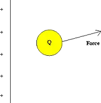
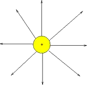
Michael Faraday introduced the concept of the Electrical Energy field. The field force acts between two charges, in the same way that the gravitational field force acts between two masses. However, the electric field is a little bit different. Gravitational force depends on the masses of two bodies, whereas the electromagnetic force depends on the electric charges of two bodies. While gravity can only pull two masses together, the force can be attractive or repulsive. If both charges are of the same sign (e.g. both positive), there will be a repulsive force between the two. If the charges are opposite, an attractive force will exist between the two bodies (as seen in static electricity and kinetic energy). The magnitude of the force varies inversely with the square of the distance between the two bodies and is also proportional to the product of the unsigned magnitudes of the two charges. Discover how electrical load determines the demand placed on a system’s energy supply.


Electrical Energy and Voltage Explained

The electric potential difference between two points is defined as the work done per unit charge (against forces) in moving a positive point charge slowly from one point to another. Choose one point as a reference with zero potential. The electric potential at any other point equals the work required per unit charge to move a positive test charge from the reference point to that location. For isolated charges, the reference point is usually taken to be infinity. The potential is measured in volts. (1 volt = 1 joule/coulomb) The electric potential is analogous to temperature: there is a different potential at every point in space, and the potential gradient indicates the direction and magnitude of the driving force behind electric current flow. Similarly, there is an electric potential at every point in space, and its gradient indicates the direction and magnitude of the driving force behind the movement of charged energy. To understand how voltage influences electrical energy, it's essential to grasp how potential difference drives current through circuits.


Electric Current: Flow of Charge That Powers Technology

Current is a flow of electrical energy, and its intensity is measured in amperes. Examples of electric currents include metallic conduction, where electrons flow through a conductor such as a metal wire, and electrolysis, where ions (charged atoms) flow through liquids. The particles themselves often have energy to move quite slowly, while the moving electric field that drives them propagates at close to the speed of light. See energy conduction for more information. Alternating current and direct current each transfer electrical energy differently, depending on the application.

Devices that utilize charge flow principles in materials are referred to as electronic devices.

A direct current (DC) is a unidirectional flow, while an alternating current (AC) reverses direction repeatedly. The time average of an alternating current is zero, but its capability (RMS value) is not zero.

Ohm's Law is an important relationship describing the behaviour of energy, relating it to voltage. Explore the principles behind Ohm’s Law to see how voltage, current, and resistance interrelate in determining energy flow. Learn how electrical resistance affects energy loss and heat generation in systems.

For historical reasons, power is said to flow from the most positive part of a circuit to the most negative part. The current thus defined is referred to as conventional current. It is now known that, depending on the conditions, a current can consist of a flow of charged particles in either direction, or even in both directions at once. The positive-to-negative convention is widely used to simplify this situation. If another definition is used - for example, "electron current" - it should be explicitly stated.


Related Articles


View more

Free Electricity Explained

Free electricity is power generated without fuel costs, typically from solar or wind sources. After setup, systems like solar panels can reduce or eliminate bills through net metering, helping promote sustainability and energy independence for homes and businesses.


What is Free Electricity?

Free electricity refers to energy that costs nothing to generate after initial setup, typically utilizing natural sources.

✅ Harnesses renewable energy sources like solar panels and wind turbines

✅ Reduces or eliminates long-term electricity costs

✅ Promotes sustainable and eco-friendly living solutions


The Reality of Free Electricity

True “free electricity” does not exist in the sense of unlimited, no-cost power available without investment. However, generating your electricity at home through solar panels or small wind systems can reduce your reliance on the power grid and lower your energy bills significantly, sometimes to zero. This cost reduction is what many people mean when they refer to "free electricity."

Purchasing and installing a solar power system is not free, but it pays off over time. It’s a long-term investment that benefits both the environment and your finances. Some homeowners even reach the point where their solar systems generate more electricity than they use.

In such cases, through a policy known as net metering, these homeowners can send excess electricity back to the power grid and receive compensation from their utility company.


What is Net Metering?

Net metering is a billing arrangement that allows consumers who generate their own electricity to send excess power back to the grid and receive credit for it. Here’s how it works:

  • Net metering allows you to sell the electricity produced by a solar system on your home back to the electric power grid.

  • Net Metering occurs when your meter spins backwards as solar electricity is being produced, storing the excess energy on the grid.

  • Once energy is actually being consumed, your meter spins forward to collect the energy that has been saved on your electric power grid.

  • For the energy that you do not consume, the electric utility will compensate you. If you get paid enough money from the electricity that you don't use and sell to them, then that profit can be used to pay for your existing consumption, making it essentially free electricity.

Some utilities offer cash payments for the surplus, while others provide energy credits that reduce your bill. Either way, your electricity costs can be significantly reduced—and in some cases, essentially eliminated.


Key Considerations for a Free Electricity System

A few things to watch out for when choosing to invest in a Free Electricity solar power system.

  • You must conserve your energy consumption to ensure that you don't exceed the amount of solar energy produced.

  • By exceeding the amount of power generated many times for the grid or saved, you are then charged regular rates for electricity provided by your electric utility.

  • You must watch your solar energy production. Keep track of the daily energy production of your system.

  • Check your utility bill each month to ensure that you are credited or reimbursed for any and all extra energy generated.

  • To control your electricity usage, consider using a time-of-use electric meter to further capitalize on your investment.


Utility Policies Vary

Not all utility companies offer generous net metering. Some may only provide energy credits, while others pay wholesale rates for your excess electricity. It's essential to check with your local utility to understand how they handle customer-generated power.

While the term “free electricity” is somewhat misleading, it does accurately reflect the very real possibility of generating low-cost or no-cost power after your initial system is installed. Through renewable energy systems and programs like net metering, homeowners can reduce or eliminate energy bills and make a lasting contribution to a cleaner, more sustainable future.


Related Articles


View more

Green Electricity

Green electricity integrates renewable energy sources such as solar PV, wind turbines, and hydropower into smart grids, improving power quality, decarbonization, efficiency, and reliability for industrial loads and utility-scale networks.


What is green electricity?

Green electricity is renewable-source power via smart grids to cut emissions and enhance system efficiency.

✅ Integrates PV, wind, hydro with power electronics and converters

✅ Enhances grid stability via inverters, FACTS, and smart protection

✅ Reduces CO2, improves efficiency, supports microgrids and storage


Green electricity is a term describing what is thought to be environmentally friendly sources of electricity. Typically, this refers to renewable and non-polluting energy power sources. For a broader perspective on how different technologies contribute, see this overview of sources of electricity across modern grids.

Green electricity includes natural energetic processes which can be harnessed with little pollution. Anaerobic digestion, geothermal power, wind power, small-scale hydropower, solar power, biomass power, tidal power and wave power fall under such a category. Some versions may also include power derived from the incineration of waste. Comparisons with other clean options are summarized in this guide to alternative electricity solutions used worldwide.


Energies Wind Electricity 
The winds that blow across the UK can be harnessed by turbines to provide Green electricity. Wind turbines sited in suitable locations already provide a small, but growing percentage of the UK's electricity, and are used successfully all around the world. In fact wind power is the world's fastest growing energy source! Wind turbine technology has greatly improved over the last ten years, making wind turbines quieter and more efficient so that electricity generated from the wind is now often competitive with traditional coal-fired and nuclear power stations. Wind turbines are also beginning to be built at sea — in the future much of our electricity could come from these offshore windfarms. Understanding how turbines integrate into national systems is covered in this primer on electricity generation methods and planning.


Solar Electricity
Many people believe that we don't get much solar Green electricity here in the UK. In fact solar power is already being used to provide essential power for many types of equipment being used in both remote and urban areas across the country. A solar photovoltaic (PV) module works by converting sunlight directly into electricity (even on cloudy days) using semiconductor technology. The vast majority of solar modules available today use "waste" silicon from the computer chip industry as the semiconductor material. They can be integrated into buildings and even made into roof tiles virtually indistinguishable from normal tiles. 
Solar Electricity can also be used to heat water directly using specially designed collectors. Even in winter a useful amount of hot water can be produced from roof top collectors. A third way to use solar energy is simply to design buildings to make maximum use of the sun. Using this so-called 'passive solar' approach, much of the energy that we currently use for heating, lighting and air conditioning can be saved. Homeowners can explore practical steps to generate electricity with rooftop PV and storage.


Hydro Electricity
Water turbines have been used to provide Green electricity for over 100 years and presently provide over 1% of the UK's electricity. Although most of the possible sites for large hydropower stations in the UK have already been developed, there is a large potential for smaller schemes. These can either use a small dam or work as a 'run of the river' system which has a minimal impact on the local environment. Design considerations for small schemes are outlined in this resource on water electricity systems for communities.


Wave Electricity
Many different devices have been designed over the years to try and capture some of this huge energy resource — the latest one has recently started generating Green electricity on the isle of Islay, off the West Coast of Scotland. In this machine waves hitting the shore are channelled into a large tube to power a specially designed turbine. With the proper support, wave power could provide a significant proportion of the UK's electricity needs in the future.


Tidal Electricity
Tidal power has been used in Britain for over a thousand years — at the time of the Doomsday book over 5,000 tide powered mills were recorded. Unlike other Green electricity renewable energy sources, which depend on the weather, tidal power is as predictable as the tides themselves. One way to capture tidal energy is to build a barrage across an estuary, storing water behind it as the tide rises and then releasing the stored water through turbines at low tide. Several sites around the UK could be suitable for this type of tidal system, the largest being the Severn Estuary. Another way is to use 'marine current turbines', which work like underwater wind turbines, harnessing tidal currents instead of the winds.


Geothermal Electricity
Geothermal energy comes from hot rocks deep underground. In some parts of the world steam comes to the surface and can be used to run steam turbines to produce Green electricity directly. In other places water can be pumped down and heated by the rocks to make steam. Geothermal energy can also be used to provide hot water and heating for buildings. Case studies of enhanced systems are available in this overview of geothermal electricity projects worldwide.


Biomass Electricity
Either agricultural wastes or specially grown plants can be used as a fuel to run small Green electricity power stations. As plants grow they absorb carbon dioxide (the main gas responsible for climate change) which is then released when the plants are burnt. So using biomass does not add any extra carbon dioxide into the atmosphere. Specially grown 'energy crops' provide not only an environmentally sound source of electricity, but also an important new opportunity for farmers. Analyses of supply chains and grid impacts appear in this review of electricity production from biomass and other renewables.


Landfill gas Converted to Electricity
As rubbish decomposes in the landfill sites where our household waste is dumped, it gives off methane gas. This gas can be captured and burnt in a gas turbine to produce an attractive Green electricity tariff. Burning the gas does give off carbon dioxide but since methane, which is emitted from the landfill site, is in fact a much more powerful greenhouse gas it is better to burn it than to allow the methane to escape into the atmosphere. There are already many landfill gas systems operating in the UK.


Waste Incineration Electricity
The UK generates an enormous amount of waste, and space at landfill sites is quickly running out. The best solution would be to recycle as much of the waste as possible, but instead incinerators are being constructed to burn the waste. In some cases the energy is being used to generate green electricity. However many environmentalists are still concerned about the emission of harmful dioxins and also about the loss of a valuable resources that could have been recycled. You can read about Greenpeace's views on incineration.


Related Articles

View more

Inductive Load Explained

An inductive load is common in electrical systems and can significantly impact power quality. Understanding inductive and resistive loads, as well as their impact on the quality of your electricity, is essential for designing and operating an effective electrical system.


What is an Inductive Load?

An inductive load is an electrical device or component that consumes active power while storing energy in a magnetic field due to inductance.

✅ Common in motors, transformers, and relays

✅ Impacts power factor and reactive power demand

✅ Requires compensation with capacitors for efficiency


Power Quality Analysis Training

Power Factor Training

Request a Free Power Quality Training Quotation

In power systems, an inductive load affects the flow of electrical current through conductors, creating conditions that may necessitate careful monitoring. A hot wire and a neutral wire must be properly balanced to avoid hazards, while ground fault circuit interrupters play a vital role in protecting against dangerous faults. Recognizing early signs of a short circuit, such as tripped breakers or overheating, is essential for maintaining system reliability and preventing equipment damage.


How does it affect Power Quality?

Inductive load affects power quality by introducing reactive power into an electrical system. Reactive power is the power that an IL consumes but does not convert into useful work. This can cause a decrease in the overall PF of the system. A low power factor (PF) can result in increased losses, decreased efficiency, and increased power source costs. Additionally, inductive loads can cause voltage drops and fluctuations, which can affect the operation of other electrical devices. Because inductive devices consume reactive power, engineers often use the apparent power formula to calculate their influence on system demand.


What are the types of inductive load?

There are several types of inductive loads, including electric motors, transformers, and heating elements. Electric motors are used in a wide range of applications, from household appliances to industrial machinery. Transformers are used to step up or step down voltage in electrical systems. Heating elements, such as those used in ovens and stovetops, rely on the inductive heating effect to generate heat. One way to minimize the effect of inductive loads on power factor is by installing an automatic power factor controller.


Common examples include:

  • Electric motors: ILs are commonly found in electric motors used in various appliances, such as washing machines, refrigerators, and air conditioners. Electric motors require electrical energy to create a magnetic field that rotates the motor's shaft, resulting in a lagging current.

  • Transformers are devices used to transfer electrical energy from one circuit to another through electromagnetic induction. They are commonly used in distribution systems to step up or step down the voltage to the required level.

  • Fluorescent lights use a ballast to regulate the flow of electricity to the lamp. The ballast contains an IL that helps regulate the electrical current and voltage to the light.

  • Welding equipment: Welding equipment, such as arc welders, use ILs to create a strong magnetic field that is used to generate the heat required for welding.

  • Induction cooktops: Induction cooktops use magnetic fields to create heat, and this requires the use of ILs to generate the magnetic field.

  • Speakers: Speakers use ILs in their voice coils to create a magnetic field that moves the speaker cone and produces sound.

It's essential to understand the different types of electrical load in order to manage consumption and ensure the efficient operation of electrical systems. Different types of loads require different management strategies, and PF correction may be necessary to optimize energy efficiency. Accurate evaluation of an inductive circuit often requires an apparent power calculator to measure kVA, kVAR, and kW contributions.


Frequently Asked Questions

How can you measure the Power Factor of an inductive load?

The PF of an IL can be measured using a PF meter or a digital multimeter. These devices measure the PF by comparing the real power (the power that is actually converted into useful work) to the apparent power (the total power consumed by the load). The PF is then calculated as the ratio of the real power to the apparent power. Inductive devices are often compared with a resistive load, which converts all energy into heat or light without reactive power.


What is the difference between a resistive and an inductive load?

A resistive load is a type of electrical load that converts electrical energy into heat or light, such as an incandescent light bulb or a resistor. A resistive load has a PF of 1, meaning that all of the electricity consumed by the load is converted into useful work. In contrast, an IL stores energy in a magnetic field and has a PF of less than 1. This means that some of the electricity consumed by the load is not converted into useful work.


What are some common examples?

Some common examples of ILs include electric motors, transformers, and fluorescent lights. These loads are found in a wide range of applications, from household appliances to industrial machinery.


How can you reduce the impact of inductive load on a system?

There are several ways to reduce the impact of ILs on an electrical system. One way is to improve the PF of the system by adding PF correction capacitors. These capacitors can help offset the reactive electricity consumed by ILs, thereby increasing the PF of the system. Another approach is to utilize soft starters or variable frequency drives with electric motors, which can reduce inrush current and minimize voltage fluctuations. Finally, using a high-efficiency supply or reducing the number of ILs in a system can also help reduce the impact of ILs on PQ. To balance inductive and capacitive elements, engineers apply power factor correction techniques that restore efficiency and reduce system losses.

By understanding the different types, measuring the PF, and reducing its impact on a system, electrical engineers can design and operate systems that are more efficient, reliable, and cost-effective.

It's worth noting that they are not the only types of electrical loads that can impact PQ. Capacitive loads, such as capacitors and fluorescent lights, can also introduce reactive power into a system. Additionally, purely resistive loads, such as resistors and incandescent light bulbs, do not introduce reactive power but can still affect PQ in other ways, including the generation of heat.

Understanding the different types of electrical loads and their impact on PQ is essential for designing and operating efficient and reliable electrical systems. While they can introduce reactive power and affect PF, there are ways to minimize their impact and improve PQ. By taking a holistic approach to electrical system design and operation, engineers can create systems that meet the needs of their users while minimizing costs and maximizing efficiency. Since inductive loads influence reactive currents, using the reactive power formula helps quantify their effect on power system design and operation.


Related Articles


View more

Electrical Resistance Explained

Electrical resistance is the opposition to the flow of electric current in a material. It is measured in ohms (Ω) and depends on the conductor’s length, thickness, material, and temperature.


What is Electrical Resistance?

Electrical resistance is a fundamental concept in engineering that defines how much a material opposes the flow of electric current. Measured in ohms (Ω), resistance (Ω) plays a crucial role in circuit design, power distribution, and electronic applications.

✅ Measured in ohms (Ω) and calculated using Ohm’s Law

✅ Influenced by material, length, area, and temperature

✅ Key factor in circuit safety, design, and energy loss


Think of electricity moving like water through a pipe. If the pipe is narrow or obstructed, less water flows through it. Similarly, in a wire or conductor, certain materials make it harder for electrons to move freely. This obstruction results in energy loss, often seen as heat.

The ease or difficulty of electric charge movement depends on the conductivity of a material. Metals like copper allow current to flow easily, while rubber or glass inhibit it entirely. This behavior plays a key role in how systems are designed and protected. Discover how resistors are used in circuits to manage voltage and protect components by providing controlled resistance.


Electrical Resistance – Example Values by Material/Component

Material/Component Approx. Resistance Notes
Copper wire (1 meter, 1mm²) ~0.017 ohms Very low resistance, ideal for conductors
Aluminum wire (1m, 1mm²) ~0.028 ohms Higher resistance than copper
Iron wire (1m, 1mm²) ~0.10 ohms Often used in heating elements
Nichrome wire (1m, 1mm²) ~1.10 ohms High-resistance alloy used in toasters and heaters
Human body (dry skin) 1,000–100,000 ohms Varies greatly with moisture and contact
Incandescent light bulb ~240 ohms (cold) Resistance increases when hot
Resistor (carbon film) Fixed (e.g., 220 ohms) Used to control current in circuits
Air (dry) ~1 trillion ohms (insulator) Excellent natural insulator unless ionized
Superconductor 0 ohms Only at extremely low temperatures (near absolute zero)


Electrical Resistance Definition

Several factors affecting electrical resistance include the type of material, temperature, and the dimensions of the conductor. When an electric charge moves through a material, its ease of flow depends on the material’s conductivity. A high-conductivity material allows charges to move more freely, resulting in lower resistance. The resistance of a conductor increases with its length and decreases with its cross-sectional area. Therefore, the resistance of a wire is directly related to both its physical properties and the material from which it is made. The resistance of a conductor depends heavily on its length and cross-sectional area, as outlined in our resistance formula breakdown.

This opposing property is quantified using Ohm’s Law:

R = V / I

Where:

  • R is the resistive value in ohms

  • V is voltage (volts)

  • I is current (amperes)

Another useful expression involves material properties:

R = ρ × (L / A)

Where:

  • ρ is resistivity (material-specific)

  • L is length

  • A is cross-sectional area

These formulas show that the longer or thinner the conductor, the harder it is for current to move through it.


Unit of Electrical Resistance – The Ohm (Ω)

The ohm is the SI unit of resistance, named after German physicist Georg Ohm. One ohm is defined as the resistance between two points of a conductor when a potential difference of one volt causes a current of one ampere to flow.

Common multiples:

  • kΩ (kilo-ohm) = 1,000 ohms

  • MΩ (mega-ohm) = 1,000,000 ohms

Resistance can be measured using a multimeter, and is especially important in designing and troubleshooting power  and electronic circuits. To understand how voltage and resistance interact in a circuit, see our guide on Ohm’s Law.


Ohm’s Law and Circuit Function

Ohm’s Law helps us understand how voltage, current, and resistance relate. For example:

  • Increase the resistive load, and current drops.

  • Increase voltage with fixed resistance, and current rises.

These principles help control energy flow, prevent overloads, and design efficient systems.


Measuring and Expressing Opposition

The ohm (Ω) is the standard unit used to quantify this phenomenon. One ohm means that a current of one ampere flows when one volt is applied. Components with fixed values, like resistors, are labelled accordingly—e.g., 100 Ω, 1 kΩ, or 1 MΩ.

To measure the current-limiting capacity of a material, a digital multimeter is used. It applies a small voltage and calculates the resulting current flow to determine the opposition level. If you're working with different wire types, explore the unit of electrical resistance for conversion insights and resistance ranges.


Real-World Examples of Resistance

  • Heating Elements: Toasters, ovens, and electric heaters utilize high-resistance materials, such as nichrome wire.

  • Power Transmission: Long-distance wires are designed with low resistance to reduce energy loss as heat.

  • Electronic Components: Resistors regulate current in circuits, protecting components from overload.

For real-world scenarios involving current flow, our article on voltage drop explains how resistance affects electrical efficiency over distance.


Factors Affecting Electrical Resistance

  • The resistance of a conductor depends on:

    • Material – copper vs. aluminum vs. nichrome

    • Length – longer wires restrict current more

    • Thickness – wider wires allow easier flow

    • Temperature – many materials resist current more when heated

    Thus, the resistance of a wire can vary dramatically depending on where and how it’s used. Materials with high conductivity (like silver or copper) allow electrons to move with minimal restriction, whereas poor conductors like rubber greatly hinder charge movement.


Superconductors – Zero Resistance?

In some materials, when cooled to extremely low temperatures, resistance drops to zero. These superconductors enable electricity to flow without energy loss, but their use is limited to specialized fields, such as MRI machines or experimental power lines, due to cost and cooling requirements.


Frequently Asked Questions


What causes electrical resistance?

It results from collisions between electrons and atoms in a conductor, which convert energy into heat.


What is the formula for calculating it?

 R = V/I or R = ρ × (L / A)


How is it measured?

With a multimeter in ohms (Ω), using a small test voltage and measuring current. Learn how instruments like a digital multimeter are used to measure opposition to current flow in electrical systems.


Why is this concept important?

It controls current flow, prevents damage, and enables functions like heating or dimming.


Can resistance ever be zero?

Yes—in superconductors under specific extreme conditions.

Electrical resistance is a foundational concept in understanding how electricity behaves in materials and systems. From household wiring to high-voltage power lines and sensitive electronics, it plays a crucial role in determining safety, efficiency, and performance. For a broader view on electric flow and material response, read about electrical conductivity and current electricity.


Related Articles


View more

Sign Up for Electricity Forum’s Newsletter

Stay informed with our FREE Newsletter — get the latest news, breakthrough technologies, and expert insights, delivered straight to your inbox.

Electricity Today T&D Magazine Subscribe for FREE

Stay informed with the latest T&D policies and technologies.
  • Timely insights from industry experts
  • Practical solutions T&D engineers
  • Free access to every issue

Live Online & In-person Group Training

Advantages To Instructor-Led Training – Instructor-Led Course, Customized Training, Multiple Locations, Economical, CEU Credits, Course Discounts.

Request For Quotation

Whether you would prefer Live Online or In-Person instruction, our electrical training courses can be tailored to meet your company's specific requirements and delivered to your employees in one location or at various locations.