How Does A Solid State Relay Work?
By William Conklin, Associate Editor
By William Conklin, Associate Editor
Our customized live online or in‑person group training can be delivered to your staff at your location.

A solid-state relay (SSR) utilizes semiconductor devices and optical coupling to switch AC or DC voltage loads without mechanical components. The control signal energizes an LED, triggering an isolated output circuit for fast, silent, and reliable power switching.
Understanding electrical protection systems is essential to grasping how solid-state relays enhance safety and reliability in modern circuits.
Basic Protection Relay Training
Request a Free Training Quotation
Unlike electromechanical relays (EMRs), SSRs rely on electronic circuits and optical coupling to perform switching with high precision and speed. Unlike arc fault circuit interrupter protection, which prevents fire hazards, SSRs focus on contactless switching for silent and efficient control.
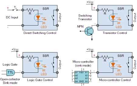
The fundamental principle behind SSR operation is electrical isolation between the control side and the load side. This is typically achieved through an optocoupler, which uses light to transmit a signal across an electrically insulating barrier. When the input circuit is energized by a low-voltage control signal, an LED inside the SSR emits light. This light is detected by a photosensitive semiconductor device, such as a phototriac, phototransistor, or photothyristor, which then switches the load circuit on or off. This optical interface ensures the control circuit and load remain electrically isolated, preventing interference and improving safety. Comparing SSRs with traditional protective relay technology shows how semiconductors and optical coupling deliver advantages in speed and durability.
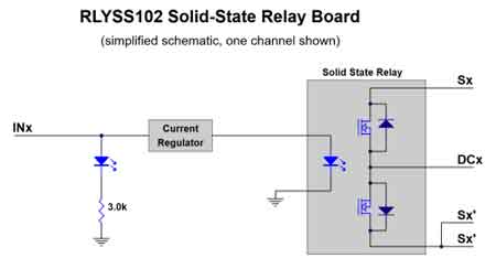
Solid state relays rely on opto-couplers or opto-isolators to achieve galvanic isolation between the control and load circuits. This optical barrier ensures safe operation by preventing electrical interference while enabling high-speed, contactless switching. Many AC SSRs use zero-cross switching to minimize electrical noise and EMI reduction, activating the relay only when the AC waveform crosses zero. On the output side, different semiconductor devices such as MOSFETs, IGBTs, thyristors, SCRs, and triacs provide precise load control, depending on whether the application is AC or DC.

While SSRs are known for their fast switching speed, silent operation, and long lifespan, they do present design considerations. A small leakage current may still flow when the relay is off, which must be accounted for in sensitive electronics. High-current SSRs also generate heat, making thermal management and proper heatsink selection critical for performance and durability. Despite these factors, SSRs offer superior reliability compared to EMRs and have fewer failure mechanisms due to the absence of moving parts. For this reason, they are widely applied in industrial automation, HVAC systems, lighting control, and motor control, where precise, efficient, and durable switching is required.
The input circuit of an SSR is designed to accept a low-power AC or DC voltage signal from a controller, PLC, or other logic device. This signal powers an LED within the optocoupler, converting electrical energy into light. The input circuits are highly sensitive, allowing small control voltages to manage larger power loads efficiently. When studying circuit breaker types, it’s useful to compare their mechanical operation with the electronic switching principles of solid state relays.
On the output side, the light from the LED activates the photosensitive element, triggering a semiconductor switch such as a triac (for AC loads) or MOSFET (for DC loads). This allows the SSR to control high-power devices using minimal input energy. Because there are no moving parts, switching is instantaneous and free from mechanical wear.
The optical coupling mechanism is the defining feature of SSRs. It ensures that high voltages in the output circuit do not feed back into the control system. This isolation barrier not only protects sensitive electronics but also reduces electrical noise and improves system stability.
Unlike electromechanical relays that rely on a magnetic field to physically move contacts and complete a circuit, a solid-state device like an SSR uses power semiconductors—such as triacs for AC loads and MOSFETs for DC loads—to control current flow electronically. This design eliminates all physical contact between switching components, thereby preventing wear, arcing, and mechanical bounce. To go deeper into relay applications, our guide on solid state relays explained complements this overview of how a solid state relay works.
In AC circuits, triacs switch current by controlling the sinusoidal wave, often synchronized with the zero-cross point to minimize electrical noise and heat generation. In DC circuits, MOSFETs handle switching with high efficiency and extremely low on-resistance, enabling precise control even at low DC voltages. By utilizing these semiconductor-based switches, SSRs achieve silent, instantaneous, and reliable operation while managing a wide range of electrical loads without subjecting them to mechanical stress. In advanced circuit protection devices, SSRs stand out for their ability to provide fast switching without moving parts.
Switching Speed: SSRs can switch in microseconds, making them ideal for applications like pulse-width modulation (PWM) and fast control loops.
Low Power Control: The control signal requires very little current, which makes SSRs compatible with microcontrollers and digital logic circuits.
Leakage Current: Unlike mechanical relays, SSRs may allow a small leakage current to flow even in the off state, which must be considered when designing sensitive circuits.
Engineers often explore complex protective relays alongside solid state relays to design layered protection strategies for sensitive equipment.
Stay informed with our FREE Electrical Protection Newsletter — get the latest news, breakthrough technologies, and expert insights, delivered straight to your inbox.
| Feature / Aspect | Solid State Relay (SSR) | Electromechanical Relay (EMR) |
|---|---|---|
| Switching Mechanism | Semiconductor devices (triacs, MOSFETs, IGBTs) | Mechanical contacts moved by electromagnetic coil |
| Isolation Method | Optical coupling (LED and photosensitive device) | Physical air gap between contacts |
| Switching Speed | Microseconds (ideal for fast, precise control) | Milliseconds (slower response due to moving parts) |
| Noise & Vibration | Silent operation, no moving parts | Audible clicking, mechanical vibration |
| Durability & Lifespan | Very high; no contact wear | Limited by mechanical wear and arcing |
| Control Signal Requirement | Low-power input compatible with PLCs and digital logic | Higher coil current needed |
| Leakage Current | Small leakage current possible even when off | Complete isolation when off |
| Applications | Automation, industrial control, HVAC, power electronics, high-frequency switching | General switching, automotive, industrial, low-frequency applications |
The operation of an SSR can be broken down into five key stages, from the moment a control signal is applied to when the load is switched:
A low-power control signal, often from a PLC or microcontroller, is applied to the input terminals. This signal can be AC or DC voltage, depending on the SSR design.
The input circuit converts this electrical signal into light using a built-in light-emitting diode (LED). This LED is crucial for optical coupling and forms the interface between the input and output sides.
The light generated by the LED crosses an electrically insulating barrier and strikes a photosensitive semiconductor device (e.g., phototriac, photothyristor, or phototransistor). This process maintains electrical isolation between the control and load circuits.
The photosensitive component triggers a power switching element, such as a triac for AC loads or MOSFET/IGBT for DC loads. This device then allows the main power to flow from the power supply to the connected load.
The load circuit is energized without any mechanical movement. When the control signal is removed, the LED turns off, the optical path is broken, and the output semiconductor stops conducting, thereby cutting power to the load. This entire process is virtually instantaneous and contact-free.
Explore 50+ live, expert-led electrical training courses –