Delta Wye Transformer Behavior in Real Distribution Systems
By Howard Williams, Associate Editor
By Howard Williams, Associate Editor
Our customized live online or in‑person group training can be delivered to your staff at your location.

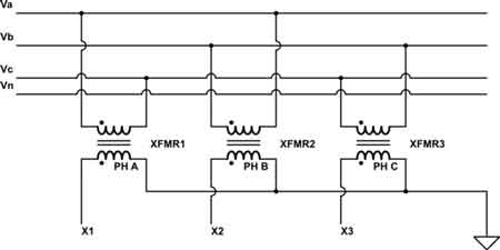
A delta wye transformer converts three phase power from a delta primary to a wye secondary to produce a grounded neutral for systems such as 208Y/120V. The connection introduces a 30 degree phase shift and helps contain triplen harmonics while stabilizing line to neutral voltages.
A delta wye transformer is chosen less for theory than for practicality. It creates a usable four-wire secondary with a stable neutral while keeping upstream systems insulated from downstream imbalance, harmonics, and grounding behavior. What matters is not that it steps down the voltage, but that it defines a boundary where real-world loads begin to behave differently.
In most facilities, that boundary marks the point where ideal three-phase assumptions give way to mixed reality. Lighting panels, receptacles, electronic loads, and drives coexist, and the system needs a neutral that behaves predictably. That is why delta-wye remains common in commercial and industrial distribution, especially where 208Y/120V or similar secondaries are unavoidable. For a broader background on transformer types and roles, see the overview of electrical transformers.
Delta wye transformer connections are rarely chosen in isolation. They sit between two worlds. Upstream, the supply is often treated as a three-wire system where imbalance is tolerated or ignored. Downstream, single-phase loads dominate behavior, and the neutral becomes an active conductor rather than a conceptual reference.
That boundary role is what differentiates delta-wye from other step-down configurations. The wye secondary does not simply “add a neutral.” It establishes a reference point that governs grounding behavior, fault response, and voltage stability under uneven loading. This is why delta-wye is often used to feed secondary distribution panels and plant services rather than tightly controlled motor-only systems, a role shared with other step-down transformers.

This page does not re-teach the difference between delta and wye windings. That foundational comparison belongs on your delta vs wye transformer guide. Here, the focus is on how the combined connection behaves once it is installed and forgotten.
It is common to hear delta-wye described as “providing a neutral,” as if the neutral were a passive feature. In practice, it becomes one of the most consequential conductors in the system. It defines grounding options, stabilizes line-to-neutral voltages, and determines how faults actually return.
A solidly grounded wye behaves very differently from a resistance-grounded one, particularly during ground faults. The delta wye transformer connection allows that choice, but it does not resolve the consequences. Fault current magnitude, protective device response, and damage energy are shaped by grounding decisions made after the transformer is installed.
This is where the delta-wye is often unfairly blamed. The connection itself is stable. The outcomes depend on how intentionally the neutral is treated, especially compared with systems supplied through isolation transformers, where grounding is deliberately decoupled and fault behavior is fundamentally different.
A delta wye transformer introduces a 30-degree phase displacement between the primary and secondary. In steady operation, that shift is invisible. The problems appear only when systems change.
Paralleling transformers, adding onsite generation, reconfiguring switchgear, or extending protection schemes can all expose assumptions that quietly ignore vector relationships. Protective relays, metering, and control logic often presume phase alignment that no longer exists once a delta-wye interface is introduced.
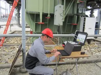
That is why experienced commissioning teams treat vector group confirmation as a prerequisite, not just paperwork. Before energization, phase rotation, polarity, and vector relationships are verified, especially in systems that rely on instrument inputs such as current transformers and voltage sensing. The phase shift is not a flaw, but it is unforgiving when forgotten.
One reason delta-wye persists is its ability to contain certain triplen harmonic currents. Delta windings in delta-wye transformers allow components to circulate internally rather than propagate upstream, helping protect utility systems and upstream equipment from downstream distortion.
That benefit is real, but limited. Harmonics do not disappear on the secondary. They still affect conductor heating, neutral loading, and transformer losses. Facilities with dense nonlinear loads, variable-frequency drives, or rectifier-based equipment quickly discover that the delta winding is a mitigation, not a solution.
When heat, efficiency, or unexplained nuisance behavior becomes an issue, the root cause is rarely the transformer connection alone. It is the interaction between load profile, neutral currents, and transformer design assumptions that were never revisited after installation.
Most field issues with delta wye transformers trace back to assumptions that outlived the systems they were designed for. Loads change. Sources multiply. Protection evolves. The transformer remains, quietly enforcing constraints no one is actively checking.
Phase shift becomes relevant only when systems interact. Neutral currents matter only when single-phase loading grows. Grounding choices matter most when faults occur under non-ideal conditions. None of these show up on a one-line diagram until something fails.
That is why verification and periodic reassessment matter more than initial selection. Testing and validation are better addressed in focused discussions such as transformer performance checks and fault behavior analysis, which are covered separately on the transformer testing page.
Delta-wye remains common because it aligns with how facilities actually behave, not how they are drawn. It tolerates upstream realities, produces a usable secondary, and gives engineers control over grounding rather than forcing it upstream. When it causes trouble, the cause is almost never the connection itself. It is forgotten phase relationships, casual grounding decisions, or a system that changed without anyone revisiting why the transformer was installed in the first place.
Think you know Electrical Transformers? Take our quick, interactive quiz and test your knowledge in minutes.
Advantages To Instructor-Led Training – Instructor-Led Course, Customized Training, Multiple Locations, Economical, CEU Credits, Course Discounts.
Request For QuotationWhether you would prefer Live Online or In-Person instruction, our electrical training courses can be tailored to meet your company's specific requirements and delivered to your employees in one location or at various locations.