Cable Handling and Testing Procedures
By R. Brownhill, P.Eng
By R. Brownhill, P.Eng

Cable handling and testing procedures ensure safe installation, correct bend radius, proper termination, and compliance via insulation resistance, continuity, and hipot tests, TDR fault locating, grounding checks, and IEC/IEEE standards adherence.
PRE-INSTALLATION
To ensure safety during cable installation and reliability once the cable is installed, you should confirm the following prior to installation: • The cable selected is proper for your application • The cable has not been damaged in transit or storage Review all applicable state and national codes to verify that the cable chosen is appropriate for the job. Also, consult your local building authority. Next, you must identify any existing cable damage and prevent any further damage from occurring. This is done through proper cable inspection, handling and storage. Consulting resources such as a guide to electrical cable classifications can help verify selections before work begins.
CABLE INSPECTION
Inspect every cable reel for damage before accepting the shipment. Be particularly alert for cable damage if:
For older distribution systems, an assessment overview of XLPE and PILC cables outlines common defect modes to consider during receipt inspection.
CABLING HANDLING
Remove all nails and staples from the reel flanges before moving a reel, and avoid all objects that could crush, gouge or impact the cable when moving. NEVER use the cable as a means to move a reel. When unreeling, observe recommended bending radii, use swivels to prevent twisting and avoid overruns.
Think you know Wiring Devices? Take our quick, interactive quiz and test your knowledge in minutes.
If the route includes tray systems, follow best practices for installing cable in cable trays to minimize damage during pulling and dressing.
CABLE INSTALLATION
A survey of customer complaints revealed that 92% of the cables in question failed due to mechanical damage. When does mechanical damage usually occur? During installation. In fact, most cables are subjected to more mechanical stress during installation than they ever experience in actual operation. Needless to say, handling and pulling your cable according to manufacturer’s recommendations is extremely important. There are five main considerations in any cable installation:
For detailed field methods and safety precautions, refer to installation guidance for conductors and cables to plan equipment, pulling tensions and lubricant use.
AMBIENT TEMPERATURE
Low temperatures are a cause for concern when installing cable. The following are temperatures below which cable should not be installed.
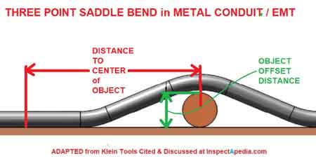
PHYSICAL LIMITATIONS TRAINING AND BENDING
Training is the positioning of cable which is not under tension. Bending is the positioning of cable which is under tension. When installing cable, the object is to limit these forces so that the cable’s physical and electrical characteristics are maintained for the expected service life. The recommended limits are:
Beyond bend limits, using properly rated cable cleats helps restrain short-circuit forces and protect insulation integrity in tray and ladder runs.
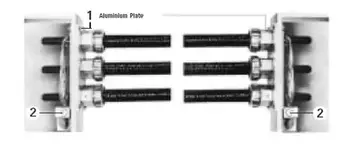
The problem is compounded by the fact that most tapes are under jackets which conceal such damage. The shielding bedding tapes or extruded polymers have sufficient conductivity and coverage initially to pass acceptance testing, then fail prematurely due to corona at the shield/insulation interface. Remember that offsets are bends.
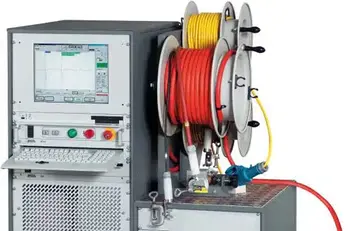
CABLE TESTING
Prior to performing the “Hi-Pot” tests, it is recommended that all insulated conductors should be meggered (insulation resistance tests) – See the formula below. The test voltage should be increased in steps of 10kV, or minimum of 5 steps. The duration at each step should be long enough for the current to reach a steady value (1 minute suggested).
For context on acceptance and maintenance test choices, see an overview of power cable testing that compares DC, VLF and tan delta applications.
The test current will momentarily increase for each voltage increment due to charging of the capacitance and the dielectric absorption characteristics of the insulation. Stabilized current should be recorded at each step. The maximum test voltage should be maintained for 15 minutes (new cable, shielded)/5 minutes (non-shielded). Leakage current should be recorded each minute after the maximum test voltage has been reached. Increase of leakage current at any step point may be an indication of a cable insulation problem.
To trend condition over time and pinpoint localized issues, power cable diagnostics techniques integrate partial discharge, VLF and oscillating-wave tests for actionable insights.
Failure of the cable or cable accessories may result unless the voltage is rapidly reduced. Otherwise, the leakage current should stabilize after about 5 minutes. Leakage current is essentially a function of the construction and length of cable but it can be influenced by the test conditions (wind and humidity) as well as the test apparatus (leads).

Typical leakage currents in the order of 100 – 150 microamperes are not unusual. A defective installation is identified by high or fluctuating leakage current with time, at a fixed DC voltage. All testing should be performed by qualified personnel taking all appropriate safety precautions.
From: Wire and Cable and Wiring Methods Handbook, Vol 3, The Electricity Forum
Explore 50+ live, expert-led electrical training courses –