Insulation Resistance Explained
By Ali Naderian, PhD, PEng, SM IEEE
By Ali Naderian, PhD, PEng, SM IEEE

Insulation resistance indicates how effectively insulation prevents current leakage, thereby supporting electrical safety and reliability. Testing measures dielectric strength, detects moisture and aging, and guides maintenance to avoid faults while extending equipment life.
The Insulation Resistance (IR) test, often referred to as the Megger test, is over 100 years old and is considered a straightforward test. During my 15 years of inspection and testing work in Canada, the US, and internationally, I have observed various practices for performing and interpreting IR tests. Understanding dielectric voltage testing is essential when evaluating insulation resistance because it helps verify insulation strength under applied electrical stress.
The application of the IR test includes:
At the time of installation, pre-commissioning is performed to ensure minimum specifications are met
Verify proper installation after a repair
Troubleshooting and
Periodic preventive maintenance
The value of insulation resistance depends on the equipment type and voltage rating, and is very sensitive to temperature. The results of the IR test typically fall within the range of 10 MΩ to 100 GΩ or higher. The acceptable level of IR depends on the equipment type, voltage class, and age of the equipment. Manufacturers usually provide the minimum recommended IR for the new equipment. In the absence of such data, IEEE 43-2013 and ANSI/NETA ATS-2013 guides could be referenced. Insulation resistance testing often works hand in hand with a dielectric voltage withstand test to confirm equipment reliability and safety standards in the field.
The insulation resistance test voltage is typically between 500V and 10kV, and the test is 1 min. Negative polarity is preferred to accommodate the phenomenon of electroendosmosis. Due to safety concerns related to high voltage, restricting workers' access to high voltages is mandatory. An arc flash suite is not necessary, but the use of personal protective equipment is recommended, as is the use of hot sticks, insulated ladders, and a ground stick for discharge. Accurate insulation resistance measurements depend on proper grounding, which can be supported through the use of a ground tester to eliminate false leakage currents.
Stay informed with our FREE HV Testing & Maintenance Newsletter — get the latest news, breakthrough technologies, and expert insights, delivered straight to your inbox.
There are several insulation resistance test methods:
1-min insulation resistance test. The reading is compared to the minimum insulation resistance specification.
Yearly insulation resistance test. A flat yearly trend indicates insulation is healthy.
Dielectric Absorption Ratio (DAR): the ratio of a 60-second reading divided by a 30-second reading.
Polarization Index (PI): the ratio is a 10-minute reading divided by a 1-minute reading
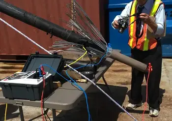
The surface leakage current is dependent on external contamination on the surface, such as dust and moisture. The surface leakage current may be significantly high for bushings, terminations, insulation surfaces, and large generators or motors that are contaminated. To eliminate surface leakage current, which reduces the accuracy of the insulation resistance measurement, a third terminal, known as the guard terminal, is used. The guard terminal shunts the measurement circuit, bypassing the leakage current. For more advanced validation of insulation resistance, utilities may also apply a hipot test to confirm dielectric integrity in high-voltage systems.
The temperature of the test object has a significant impact on the test results. The test results must be corrected to 20°C using ANSI/NETA ATS-2013 or corrected to 40°C using IEEE 43-2013.
Insulation resistance test using the guard probe ( blue wire) at the cable shield for better reading
The following are ten recommendations that could be considered to improve the test results:
1. Negative polarity is preferred to accommodate the phenomenon of electroendosmosis.
2. Record the temperature and use the compensation factor to correct results to 20 0C for cables, transformers, and insulators and to 40 0C for motors and generators.
3. If it is humid or the equipment surface is not clean, use the “Guard Probe” to bypass the leakage current and for better accuracy.
4. If an underground cable is tested, compensate for the cable length as per ANSI/NETA ATS-2013.
5. For new equipment, if there is no recommendation from the manufacturer, use ANSI/NETA ATS-2013 or IEEE 43-2013.
6. For service-aged equipment, if there is no recommendation from the manufacturer, compare the phases to similar-age equipment.
7. Set up the leads at a distance from one another and without contact with any objects or with the floor to limit the possibility of leakage currents within the measurement line itself.
8. After the test is complete, make sure that the circuit is discharged. It can be discharged by short-circuiting the test set terminals and connecting them to ground.
9. Use the polarization index (PI) or dielectric absorption ratio (DAR) only when the insulation resistance is questionable. Otherwise, PI and DAR will be misleading.
10. When you buy an insulation resistance tester, make sure it is 10kV and can measure 10 Tera-ohm or higher.
To fully grasp the role of insulation resistance, see our insulation resistance explained guide, which connects related methods like line leakage testing and calibrate test equipment for accurate results.

Advantages To Instructor-Led Training – Instructor-Led Course, Customized Training, Multiple Locations, Economical, CEU Credits, Course Discounts.
Request For QuotationWhether you would prefer Live Online or In-Person instruction, our electrical training courses can be tailored to meet your company's specific requirements and delivered to your employees in one location or at various locations.