What is Inductance?
By William Conklin, Technical Editor
Inductance is the property of an electrical circuit that resists changes in current by storing energy in a magnetic field. It underpins transformers, motors, inductors, and AC power systems, making it essential in the field of electrical engineering.
What is Inductance?
This principle is central to electromagnetic induction and underlies many devices in modern power and electronics.
The principle of inductance was first discovered by Michael Faraday, who showed that moving a magnet through a coil of wire induced a voltage across the coil. This discovery, known as Faraday’s Law, explains the phenomenon of electromagnetic induction. Heinrich Lenz later refined this understanding, demonstrating that the induced voltage always acts to oppose the change that created it — a principle now known as Lenz’s Law. These discoveries underpin the operation of inductors, transformers, and motors.
Inductance occurs when a change in current flow is utilized to prevent signals with a higher frequency component from passing, while allowing signals with lower frequency components to pass. This is why inductors are sometimes referred to as "chokes," as they effectively block higher frequencies. A common application of a choke is in a radio amplifier biasing circuit, where the collector of a transistor needs to be supplied with a DC voltage without allowing the RF (radio frequency) signal to conduct back into the DC supply. To understand how inductance interacts with voltage changes in AC circuits, see our article on voltage.
To understand how inductance interacts with voltage changes in AC circuits, see our article on voltage.
Power Quality Analysis Training
Request a Free Power Quality Training Quotation
Imagine a wire 1,000,000 miles (about 1,600,000 kilometres) long. Imagine that we form this wire into a huge loop and then connect its ends to the terminals of a battery, as shown in Figure 1, to drive current through the wire. Inductors are often paired with capacitors in circuits, so it's helpful to review the basics of what is a capacitor and how they function.
If we used a short wire for this experiment, the current would begin to flow immediately and attain a level limited only by the resistance in the wire and the resistance in the battery. But because we have an extremely long wire, the electrons require some time to work their way from the negative battery terminal, around the loop, and back to the positive terminal. Therefore, it will take some time for the current to reach its maximum level. Since inductance is used to oppose changes in current, our guide on what is current electricity provides essential background.
The magnetic field produced by the loop will initially be small during the first few moments when current flows only in part of the loop. The field will build up as the electrons get around the loop. Once the electrons reach the positive battery terminal, allowing a steady current to flow around the entire loop, the magnetic field quantity reaches its maximum and levels off, as shown in Figure 2. At that time, we'll have a certain amount of energy stored in the magnetic field. The amount of stored energy will depend on the inductance of the loop, which depends on its overall size. We symbolize inductance, as a property or as a mathematical variable, by writing an italicized, uppercase letter L. Our loop constitutes an inductor. To abbreviate "inductor," we write an upper-case, non-italicized letter L.
Fig. 1. We can use a huge, imaginary loop of wire to illustrate the principle of inductance.
Counter EMF and the RL Time Constant
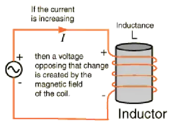
As current begins to flow in a conductor, the expanding magnetic field induces a counter-electromotive force (emf) that opposes the applied voltage. At the instant of starting, this counter emf nearly equals the source voltage, keeping the current flow small. As the magnetic field stabilizes, the counter emf weakens until the current reaches its maximum.
Because inductors resist changes in current, the current in an RL circuit cannot change instantly. The rate of change is governed by the time constant (τ):
-
After one time constant, the current reaches approximately 63% of its maximum value.
-
After 5 time constants, the current is essentially steady.
This exponential buildup parallels the charging process of capacitors in RC circuits.
Building Inductance with Coils and Cores
Obviously, we can't make a wire loop measuring anywhere near 1,000,000 miles in circumference. But we can wind fairly long lengths of wire into compact coils. When we do that, the magnetic flux for a given length of wire increases compared with the flux produced by a single-turn loop, increasing the inductance. If we place a ferromagnetic rod, called a core, inside a coil of wire, we can increase the flux density and further enhance the inductance. High-frequency signals blocked by inductors are often explained using the concept of impedance, detailed in our page on what is impedance.
We can achieve values of L many times greater with a ferromagnetic core than with a similar-sized coil having an air core, a solid plastic core, or a solid wooden core. (Plastic and dry wood have permeability values that differ little from air or a vacuum; engineers occasionally use these materials as coil cores or "forms" to add structural rigidity to the windings without significantly changing the inductance.) The current that an inductor can handle depends on the diameter of the wire. But the value of L also depends on the number of turns in the coil, the diameter of the coil, and the overall shape of the coil. Many circuits involve a balance between resistance and inductance, so reviewing what is electrical resistance will add depth to your understanding.


Key physical parameters that affect inductance include:
-
Number of turns: inductance varies as the square of the turns.
-
Cross-sectional area: a larger area increases inductance.
-
Length of the coil: Longer coils reduce inductance.
-
Core material: magnetic materials (iron, steel, nickel) concentrate flux and increase inductance.
If we hold all other factors constant, the inductance of a helical coil increases in direct proportion to the number of turns of wire. Inductance also increases in direct proportion to the diameter of the coil. If we "stretch out" a coil with a certain number of turns and a certain diameter while holding all other parameters constant, its inductance decreases. Conversely, if we "squash up" an elongated coil while holding all other factors constant, the inductance goes up. For insight into how inductors shape power quality, especially reactive power, read our overview of reactive power.
Self-Inductance
Even a straight conductor exhibits some inductance, but when the current in a coil changes, the change in the magnetic field induces a voltage across that same coil. This phenomenon is known as self-inductance, and it always opposes changes in current. The effect is central to the operation of inductors, transformers, and motor windings.
Normal and Abnormal Conditions
Under normal circumstances, the inductance of a coil (or any other type of device designed to function as an inductor) remains constant regardless of the strength of the signal we apply. In this context, "abnormal circumstances" refer to an applied signal so strong that the inductor wire melts or the core material overheats excessively. Good engineering sense demands that such conditions should never arise in a well-designed electrical or electronic system.
Fig. 2. Relative magnetic flux in and around a huge loop of wire connected to a current source, as a function of time.
Related Articles

