Define Electromagnetism

By R.W. Hurst, Editor


Electromagnetism is the branch of physics that studies the interaction between electric currents and magnetic fields. It explains how electricity generates magnetism and powers devices such as motors, generators, and transformers in modern electrical systems.


How Should We Define Electromagnetism?

Here's a good way to define electromagnetism: Electromagnetism is a branch of physics involving the study of the electromagnetic force, a type of physical interaction that occurs between electrically charged particles.

✅ Explains the relationship between electricity and magnetism

✅ Governs the operation of motors, generators, and transformers

✅ Forms the basis for electromagnetic waves like light and radio

The electromagnetic force is carried by electromagnetic fields, which are composed of electric fields and magnetic fields, and it is responsible for electromagnetic radiation, such as light.


Who Discovered Electromagnetism?

In 1820, the Danish physicist, Hans Christian Oersted, discovered that the needle of a compass brought near a current-carrying conductor would be deflected. When the current flow stopped, the compass needle returned to its original position. This important discovery demonstrated a relationship between electricity and magnetism that led to the development of the electromagnet and to many of the inventions on which modern industry is based.

Oersted discovered that the magnetic field had no connection with the conductor in which the electrons were flowing, because the conductor was made of nonmagnetic copper. The electrons moving through the wire created the magnetic field around the conductor. Since a magnetic field accompanies a charged particle, the greater the current flow, the greater the magnetic field. Figure 1 illustrates the magnetic field around a current-carrying wire. A series of concentric circles around the conductor represents the field, which, if all the lines were shown, would appear more as a continuous cylinder of such circles around the conductor.


Fig. 1 - Magnetic field formed around a conductor in which current is flowing.


As long as current flows in the conductor, the lines of force remain around it. [Figure 2] If a small current flows through the conductor, there will be a line of force extending out to circle A. If the current flow is increased, the line of force will increase in size to circle B, and a further increase in current will expand it to circle C. As the original line (circle) of force expands from circle A to B, a new line of force will appear at circle A. As the current flow increases, the number of circles of force increases, expanding the outer circles farther from the surface of the current-carrying conductor.


Fig. 2 - Expansion of magnetic field as current increases.


If the current flow is a steady, nonvarying direct current, the magnetic field remains stationary. When the current stops, the magnetic field collapses, and the magnetism around the conductor disappears.

A compass needle is used to demonstrate the direction of the magnetic field around a current-carrying conductor. Figure 3 View A shows a compass needle positioned at right angles to, and approximately one inch from, a current-carrying conductor. If no current were flowing, the north-seeking end of the compass needle would point toward the Earth’s magnetic pole. When current flows, the needle lines itself up at right angles to a radius drawn from the conductor. Since the compass needle is a small magnet, with lines of force extending from south to north inside the metal, it will turn until the direction of these lines agrees with the direction of the lines of force around the conductor. As the compass needle is moved around the conductor, it will maintain itself in a position at right angles to the conductor, indicating that the magnetic field around a current-carrying conductor is circular. As shown in View B of Figure 3, when the direction of current flow through the conductor is reversed, the compass needle points in the opposite direction, indicating that the magnetic field has reversed its direction.


Fig.3 - Magnetic field around a current-carrying conductor.


A method for determining the direction of the lines of force when the direction of current flow is known is illustrated in Figure 4. If the conductor is grasped in the left hand, with the thumb pointing in the direction of current flow, the fingers will be wrapped around the conductor in the same direction as the lines of the magnetic field. This is called the left-hand rule.


Fig.4 - Left-hand rule.


Although it has been stated that the lines of force have direction, this should not be construed to mean that the lines have motion in a circular direction around the conductor. Although the lines of force tend to act in a clockwise or counterclockwise direction, they are not revolving around the conductor.

Since current flows from negative to positive, many illustrations indicate the current direction with a dot symbol on the end of the conductor when the electrons are flowing toward the observer and a plus sign when the current is flowing away from the observer. [Figure 5]


Fig. 5 - Direction of current flow in a conductor.


When a wire is bent into a loop and an electric current flows through it, the left-hand rule remains valid. [Figure 6]


Fig. 6 - Magnetic field around a looped conductor.


If the wire is coiled into two loops, many of the lines of force become large enough to include both loops. Lines of force go through the loops in the same direction, circle around the outside of the two coils, and come in at the opposite end. [Figure 7]


Fig. 7 - Magnetic field around a conductor with two loops.


When a wire contains many such loops, it is referred to as a coil. The lines of force form a pattern through all the loops, causing a high concentration of flux lines through the center of the coil. [Figure 8]


Fig. 8 - Magnetic field of a coil.


In a coil made from loops of a conductor, many of the lines of force are dissipated between the loops of the coil. By placing a soft iron bar inside the coil, the lines of force will be concentrated in the center of the coil, since soft iron has a greater permeability than air. [Figure 9] This combination of an iron core in a coil of wire loops, or turns, is called an electromagnet, since the poles (ends) of the coil possess the characteristics of a bar magnet.


Fig. 9 - Electromagnet.


The addition of the soft iron core does two things for the current-carrying coil. First, the magnetic flux increases, and second, the flux lines become more concentrated.

When direct current flows through the coil, the core becomes magnetized with the same polarity (north and south poles) as the coil would have without the core. If the current is reversed, the polarity will also be reversed.

The polarity of the electromagnet is determined by the left-hand rule in the same manner as the polarity of the coil without the core was determined. If the coil is grasped in the left hand in such a manner that the fingers curve around the coil in the direction of electron flow (minus to plus), the thumb will point in the direction of the north pole. [Figure 10]


Fig. 10 - Left-hand rule applied to a coil.

The strength of the magnetic field of the electromagnet can be increased by either increasing the flow of current or the number of loops in the wire. Doubling the current flow approximately doubles the strength of the field, and similarly, doubling the number of loops approximately doubles the magnetic field strength. Finally, the type of metal in the core is a factor in the field strength of the electromagnet.

A soft iron bar is attracted to either pole of a permanent magnet and, likewise, is attracted by a current-carrying coil. The lines of force extend through the soft iron, magnetizing it by induction and pulling the iron bar toward the coil. If the bar is free to move, it will be drawn into the coil to a position near the center where the field is strongest. [Figure 10-35]


Fig. 11 - Solenoid with iron core.


Electromagnets are utilized in various electrical instruments, including motors, generators, relays, and other devices. Some electromagnetic devices operate on the principle that an iron core, held away from the center of a coil, will be rapidly pulled into its center position when the coil is energized. This principle is utilized in the solenoid, also known as a solenoid switch or relay, where the iron core is spring-loaded off-center and moves to complete a circuit when the coil is energized. 


Related Articles


Related News

Electricity How it Works

Electricity How It Works explains electron flow, voltage, current, resistance, and power in circuits, from generation to distribution, covering AC/DC systems, Ohm's law, conductors, semiconductors, transformers, and energy conversion efficiency and safety.


What Is Electricity How It Works?

Explains electron flow, voltage, current, resistance, and power conversion in AC/DC circuits and key components.

✅ Voltage drives current through resistance per Ohm's law (V=IR).

✅ AC/DC systems distribute power via transformers and rectifiers.

✅ Conductors, semiconductors, capacitors, inductors shape circuits.


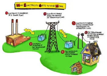
Electricity How It Works - This is a very common question. It can best be explained by stating this way: Single-phase electricity is what you have in your house. You generally talk about household electrical service as single-phase, 120-volt AC service. If you use an oscilloscope and look at the power found at a normal wall-plate outlet in your house, what you will find is that the power at the wall plate looks like a sine wave, and that wave oscillates between -170 volts and 170 volts (the peaks are indeed at 170 volts; it is the effective (rms) voltage that is 120 volts). The rate of oscillation for the sine wave is 60 cycles per second. Oscillating power like this is generally referred to as AC, or alternating current. The alternative to AC is DC, or direct current. Batteries produce DC: A steady stream of electrons flows in one direction only, from the negative to the positive terminal of the battery.

For a refresher on fundamentals, the overview at what is electricity explains charge, current, and voltage in practical terms.

AC has at least three advantages over DC in an electricity power distribution grid:

1. Large electricity generators happen to generate AC naturally, so conversion to DC would involve an extra step.
2. Electrical Transformers must have alternating current to operate, and we will see that the power distribution grid depends on transformers. 
3. It is easy to convert AC to DC but expensive to convert DC to AC, so if you were going to pick one or the other AC would be the better choice.

To connect these advantages to real-world practice, the primer on basic electricity clarifies AC versus DC behavior, impedance, and safety basics.

The electricity generating plant, therefore, produces AC. For a deeper look at how rotating machines induce AC, see the overview of electricity generators and their role in utility-scale plants.


Electricity How it Works in The Power Plant: Three-phase Power

If you want a quick walkthrough from generation to loads, this guide on how electricity works ties the concepts together before we examine three-phase specifics.

The power plant produces three different phases of AC power simultaneously, and the three phases are offset 120 degrees from each other. There are four wires coming out of every power plant: the three phases plus a neutral or ground common to all three. If you were to look at the three phases on a graph, they would look like this relative to ground:

A concise visual explainer on three-phase electricity shows how 120-degree phase offsets create balanced currents in feeders.

Electricity How It Works - There is nothing magical about three-phase power. It is simply three single phases synchronized and offset by 120 degrees. For wiring diagrams and common configurations, explore 3-phase power examples used across industrial facilities.

Why three phases? Why not one or two or four? In 1-phase and 2-phase electricity, there are 120 moments per second when a sine wave is crossing zero volts. In 3-phase power, at any given moment one of the three phases is nearing a peak. High-power 3-phase motors (used in industrial applications) and things like 3-phase welding equipment therefore have even power output. Four phases would not significantly improve things but would add a fourth wire, so 3-phase is the natural settling point.

Practical comparisons of motor torque ripple and line loading in 3-phase electricity help illustrate why three conductors strike the best balance.

And what about this "ground," as mentioned above? The power company essentially uses the earth as one of the wires in the electricity system. The earth is a pretty good conductor and it is huge, so it makes a good return path for electrons. (Car manufacturers do something similar; they use the metal body of the car as one of the wires in the car's electrical system and attach the negative pole of the battery to the car's body.) "Ground" in the power distribution grid is literally "the ground" that's all around you when you are walking outside. It is the dirt, rocks, groundwater, etc., of the earth.


Related Articles

View more

What is Voltage?

Voltage is the electrical potential difference between two points, providing the force that moves current through conductors. It expresses energy per charge, powering devices, controlling circuits, and ensuring efficient and safe operation of electrical and electronic systems.


What is Voltage?

Voltage is the electric potential difference, the work done per unit charge (Joules per Coulomb). It: 

✅ Is the difference in electric potential energy between two points in a circuit.

✅ Represents the force that pushes electric current through conductors.

✅ It is measured in volts (V), and it is essential for power distribution and electrical safety.

To comprehend the concept of what is voltage, it is essential to understand its fundamental principles. Analogies make this invisible force easier to picture. One of the most common is the water pressure analogy: just as higher water pressure pushes water through pipes more forcefully, higher voltage pushes electric charges through a circuit. A strong grasp of voltage begins with the fundamentals of electricity fundamentals, which explain how current, resistance, and power interact in circuits.

Another way to imagine what is voltage is as a hill of potential energy. A ball placed at the top of a hill naturally rolls downward under gravity. The steeper the hill, the more energy is available to move the ball. Likewise, a higher voltage means more energy is available per charge to move electrons in a circuit.

A third analogy is the pump in a water system. A pump creates pressure, forcing water to move through pipes. Similarly, a battery or generator functions as an electrical pump, supplying the energy that drives electrons through conductors. Without this push, charges would remain in place and no current would flow.

Together, these analogies—water pressure, potential energy hill, and pump—show how voltage acts as the essential driving force, the “electrical pressure” that enables circuits to function and devices to operate. Since voltage and Current are inseparable, Ohm’s Law shows how resistance influences the flow of electricity in every system.

These analogies help us visualize voltage as pressure or stored energy, but in physics, voltage has a precise definition. It is the work done per unit charge to move an electric charge from one point to another. Mathematically, this is expressed as:

V = W / q

where V is voltage (in volts), W is the work or energy (in joules), and q is the charge (in coulombs). This equation shows that one volt equals one joule of energy per coulomb of charge.

In circuit analysis, voltage is also described through Ohm’s Law, which relates it to current and resistance:

V = I × R

where I is current (in amperes) and R is resistance (in ohms). This simple but powerful formula explains how voltage, current, and resistance interact in every electrical system.

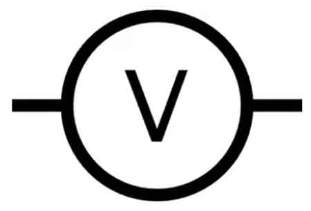
Italian physicist Alessandro Volta played a crucial role in discovering and understanding V. The unit of voltage, the volt (V), is named in his honor. V is measured in volts, and the process of measuring V typically involves a device called a voltmeter. In an electrical circuit, the V difference between two points determines the energy required to move a charge, specifically one coulomb of charge, between those points. The history of voltage is closely tied to the History of Electricity, where discoveries by pioneers like Volta and Franklin have shaped modern science.

An electric potential difference between two points produces an electric field, represented by electric lines of flux (Fig. 1). There is always a pole that is relatively positive, with fewer electrons, and one that is relatively negative, with more electrons. The positive pole does not necessarily have a deficiency of electrons compared with neutral objects, and the negative pole might not have a surplus of electrons compared with neutral objects. But there's always a difference in charge between the two poles. So the negative pole always has more electrons than the positive pole.


Fig 1. Electric lines of flux always exist near poles of electric charge.


The abbreviation for voltage measurement is V. Sometimes, smaller units are used. For example, the millivolt (mV) is equal to a thousandth (0.001) of a volt. The microvolt (uV) is equal to a millionth (0.000001) of a volt. And it is sometimes necessary to use units much larger than one volt. For example, one kilovolt (kV) is equal to one thousand volts (1,000). One megavolt (MV) is equal to one million volts (1,000,000) or one thousand kilovolts. When comparing supply types, the distinction between Direct Current and AC vs DC shows why standardized voltage systems are essential worldwide.

The concept of what is voltage is closely related to electromotive force (EMF), which is the energy source that drives electrons to flow through a circuit. A chemical battery is a common example of a voltage source that generates EMF. The negatively charged electrons in the battery are compelled to move toward the positive terminal, creating an electric current.

In power distribution, three-phase electricity and 3 Phase Power demonstrate how higher voltages improve efficiency and reliability.

Voltage is a fundamental concept in electrical and electronic systems, as it influences the behavior of circuits and devices. One of the most important relationships involving V is Ohm's Law, which describes the connection between voltage, current, and resistance in an electrical circuit. For example, Ohm's Law states that the V across a resistor is equal to the product of the current flowing through it and the resistance of the resistor. 

The voltage dropped across components in a circuit is critical when designing or analyzing electrical systems. Voltage drop occurs when the circuit components, such as resistors, capacitors, and inductors, partially consume the V source's energy. This phenomenon is a crucial aspect of circuit analysis, as it helps determine a system's power distribution and efficiency. Potential energy is defined as the work required to move a unit of charge from different points in an electric dc circuit in a static electric field.  Engineers often analyze Voltage Drop to evaluate circuit performance, alongside concepts like Electrical Resistance.

Voltage levels are standardized in both household and industrial applications to ensure the safe and efficient operation of electrical equipment. In residential settings, common voltage levels range from 110 to 240 volts, depending on the country. Industrial applications often utilize higher voltages, ranging from several kilovolts to tens of kilovolts, to transmit electrical energy over long distances with minimal losses.

Another important distinction in the realm of voltage is the difference between alternating current (AC) and direct current (DC). AC alternates periodically, whereas DC maintains a constant direction. AC is the standard for most household and industrial applications, as it can be easily transformed to different voltage levels and is more efficient for long-distance transmission. DC voltage, on the other hand, is often used in batteries and electronic devices.

Voltage is the driving force behind the flow of charge carriers in electrical circuits. It is essential for understanding the behavior of circuits and the relationship between voltage, current, and resistance, as described by Ohm's Law. The importance of V levels in household and industrial applications, as well as the significance of voltage drop in circuit analysis, cannot be overstated. Finally, the distinction between AC and DC voltage is critical for the safe and efficient operation of electrical systems in various contexts.

By incorporating these concepts into our understanding of voltage, we gain valuable insight into the world of electricity and electronics. From the pioneering work of Alessandro Volta to the modern applications of voltage in our daily lives, it is clear that voltage will continue to play a crucial role in the development and advancement of technology. Foundational principles such as Amperes Law and the Biot Savart Law complement voltage by describing how currents and magnetic fields interact.


Related Articles


View more

How to Save Electricity?

How to save electricity? Improve energy efficiency, switch to LED lighting, manage standby power, use smart thermostats, insulate homes, schedule heavy appliances off-peak, and conduct energy audits to cut power consumption and lower bills.


How to Save Electricity?

Reduce power consumption with LEDs, smart thermostats, insulation, and off-peak usage to lower energy bills.

✅ Upgrade to LED lighting and ENERGY STAR appliances

✅ Program smart thermostats; set HVAC to efficient ranges

✅ Eliminate standby power with advanced power strips


How to Save Electricity is a popular question. It involves energy conservation and lessens real dollars and preserves a public resource. Here are some ways to cut energy costs without compromising your lifestyle too much. For a deeper primer on cutting household consumption, explore this saving electricity guide for actionable steps.


Control heating and cooling costs

In some climates, heating and cooling represent the largest part of household energy use. In many climates, running your air conditioner at 78 instead of 72 will earn 40% of your cooling bill. You don't have to freeze or roast to death in order to use less energy and earn money. In some climates, heating and cooling represent the largest part of household energy use. In many climates, running your air conditioner at 78 instead of 72 will earn 40% of your cooling bill. You don't have to freeze or roast to death in order to use less energy and earn money.In some climates, heating and cooling represent the largest part of household energy use. In many climates, running your air conditioner at 78 instead of 72 will earn 40% of your cooling bill. You don't have to freeze or roast to death in order to use less energy and earn money. Here are a few tips:

Understanding how HVAC loads draw electric power can help you schedule operation during cooler periods for efficiency.

  • How to Save Electricity? Make sure your filters are clean. Check with the manufacturer of your equipment or with your utility company to see if filters on your units need to be cleaned.
  • Don't heat or cool when no one is home. If you are going to be gone for more than a half an hour, you can turn your heating or cooling off or down. Don't turn off the heat in a cold climate because that may result in the pipes breaking.
  • Supplement your main unit with portable units Running a fan can help you use less air conditioning. Using portable heaters when you are asleep or otherwise staying in one room can mean less use of heat if it means that you don't have to use the main unit.
  • Try setting your thermostat to run less frequently Turn your air conditioner up a degree or two or your heater down a degree or two and see if you still can be comfortable.
  • Time your opening and closing of windows and drapes to reduce heading and cooling costs. On cold, sunny days, opening curtains and drapes while leaving windows closed will help you heat your home. Opening the windows on summer nights helps cool your home. Buying storm windows in some climates reduces heating costs.
  • Check for holes in your roof and in your pipes. This can help reduce up to 10 per cent of your heating and cooling costs.

Track your improvements by reading your electricity meter regularly and noting weekday versus weekend patterns.


Get energy saving ideas from your utility company 

Utility companies are among the few businesses who hope that you use less of their product. Most power companies are anxious to postpone construction of new power plants, so they strongly encourage customers to use less power. 
Utility companies offer energy audits, tips, and other help for customers who want to reduce energy consumption. Call your local utility or log onto their website to see what they have to offer. Many utilities explain how electricity cost components like demand and time-of-use rates affect bills.


Other Electricity Saving tips:

  • Consider how to increase your energy efficiency when buying appliances Appliances are labeled with energy usage comparison tables. Look at these figures. Also, you may be able to buy an adapter to make your older appliances more energy efficient.
  • Turn off appliances that no one is using Turning off TV's, lamps, computers, VCR's, ovens, and other appliances that no one is using can reduce electric energy consumption. Even turning them off for short periods can produce noticeable results.
  • See if an alternative energy company is available In California, electrical deregulation is beginning to result in alternative providers of electric power. This is a trend that should increase nationally. See if that option is available to you.
  • Install low-flow heads in your water closets. Also, check your water heater's temperature and set it for 120 degrees. Putting insulation over your water heater and pipes can also help.
  • Wash and dry only full loads of clothing or dishes

Stay aware of regional electricity prices so you can plan high-use activities for lower-cost periods.

You may not make you rich, but it will help you cut down some on your costs and will help prevent blackouts and power shortages in your community.

Are your company's profits being eroded by escalating energy costs? Can you gamble that your energy costs will go down in the future? What are you doing about preparing and protecting your company from spiraling energy costs?

If you operate in competitive markets, review how electricity deregulation shapes supplier choices and contract terms.

Do you have the knowledge of the dynamic market with the right equipment that will make the 'smart decisions' and make an effective difference in your energy consumption and see your energy bill go down?

Facilities with inductive loads can cut charges by improving power factor through correction equipment and better motor controls.


Do you know about the latest technologies that you can implement now?

These questions can be answered by our new Industrial, Commercial & Institutional Energy Efficiency Handbook. This 100+ page book is jammed with practical information on reducing energy consumption, increase Energy efficiency by using modern technologies such as variable frequency drives, high efficiency electrical devices, energy efficient lighting, energy management control systems, metering and management systems, as well as fan, pump and blower efficiency improvements. We will also list Federal, State, utility and Canadian government programs that will reduce your energy consumption and increase your energy efficiency.


Related Articles

View more

What is a Watt-hour?

A watt-hour (Wh) is a unit of energy equal to using one watt of power for one hour. It measures how much electricity is consumed over time and is commonly used to track energy use on utility bills.

Understanding watt-hours is important because it links electrical power (watts) and time (hours) to show the total amount of energy used. To better understand the foundation of electrical energy, see our guide on What is Electricity?


Watt-Hour vs Watt: What's the Difference?

Although they sound similar, watts and watt-hours measure different concepts.

  • Watt (W) measures the rate of energy use — how fast energy is being consumed at a given moment.

  • Watt-hour (Wh) measures the amount of energy used over a period of time.

An easy way to understand this is by comparing it to driving a car:

  • Speed (miles per hour) shows how fast you are travelling.

  • Distance (miles) shows how far you have travelled in total.

Watt-hours represent the total energy consumption over a period, not just the instantaneous rate. You can also explore the relationship between electrical flow and circuits in What is an Electrical Circuit?


How Watt-Hours Are Calculated

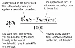
Calculating watt-hours is straightforward. It involves multiplying the power rating of a device by the length of time it operates.
The basic formula is:

Energy (Wh) = Power (W) × Time (h)

This illustrates this relationship, showing how steady power over time yields a predictable amount of energy consumed, measured in watt-hours. For a deeper look at electrical power itself, see What is a Watt? Electricity Explained


Real-World Examples of Watt-Hour Consumption

To better understand how watt-hours work, it is helpful to examine simple examples. Different devices consume varying amounts of energy based on their wattage and the duration of their operation. Even small variations in usage time or power level can significantly affect total energy consumption.

Here are a few everyday examples to illustrate how watt-hours accumulate:

  • A 60-watt lightbulb uses 60 watt-hours (Wh) when it runs for one hour.

  • A 100-watt bulb uses 1 Wh in about 36 seconds.

  • A 6-watt Christmas tree bulb would take 10 minutes to consume 1 Wh.

These examples demonstrate how devices with different power ratings achieve the same energy consumption when allowed to operate for sufficient periods. Measuring energy usage often involves calculating current and resistance, which you can learn more about in What is Electrical Resistance?


Understanding Energy Consumption Over Time

In many cases, devices don’t consume energy at a steady rate. Power use can change over time, rising and falling depending on the device’s function. Figure 2-6 provides two examples of devices that each consume exactly 1 watt-hour of energy but in different ways — one at a steady rate and one with variable consumption.

Here's how the two devices compare:

  • Device A draws a constant 60 watts and uses 1 Wh of energy in exactly 1 minute.

  • Device B starts at 0 watts and increases its power draw linearly up to 100 watts, still consuming exactly 1 Wh of energy in total.

For Device B, the energy consumed is determined by finding the area under the curve in the power vs time graph.
Since the shape is a triangle, the area is calculated as:

Area = ½ × base × height

In this case:

  • Base = 0.02 hours (72 seconds)

  • Height = 100 watts

  • Energy = ½ × 100 × 0.02 = 1 Wh

This highlights an important principle: even when a device's power draw varies, you can still calculate total energy usage accurately by analyzing the total area under its power curve.

It’s also critical to remember that for watt-hours, you must multiply watts by hours. Using minutes or seconds without converting will result in incorrect units.


Fig. 2-6. Two hypothetical devices that consume 1 Wh of energy.


Measuring Household Energy Usage

While it’s easy to calculate energy consumption for a single device, it becomes more complex when considering an entire household's energy profile over a day.
Homes have highly variable power consumption patterns, influenced by activities like cooking, heating, and running appliances at different times.

Figure 2-7 shows an example of a typical home’s power usage throughout a 24-hour period. The curve rises and falls based on when devices are active, and the shape can be quite complex. Saving energy at home starts with understanding how devices consume power; see How to Save Electricity

Instead of manually calculating the area under such an irregular curve to find the total watt-hours used, electric utilities rely on electric meters. These devices continuously record cumulative energy consumption in kilowatt-hours (kWh).

Each month, the utility company reads the meter, subtracts the previous reading, and bills the customer for the total energy consumed.
This system enables accurate tracking of energy use without the need for complex mathematical calculations.


Fig. 2-7. Graph showing the amount of power consumed by a hypothetical household, as a function of the time of day.


Watt-Hours vs Kilowatt-Hours

Both watt-hours and kilowatt-hours measure the same thing — total energy used — but kilowatt-hours are simply a larger unit for convenience. In daily life, we usually deal with thousands of watt-hours, making kilowatt-hours more practical.

Here’s the relationship:

  • 1 kilowatt-hour (kWh) = 1,000 watt-hours (Wh)

To see how this applies, consider a common household appliance:

  • A refrigerator operating at 150 watts for 24 hours consumes:

    • 150 W × 24 h = 3,600 Wh = 3.6 kWh

Understanding the connection between watt-hours and kilowatt-hours is helpful when reviewing your utility bill or managing your overall energy usage.

Watt-hours are essential for understanding total energy consumption. Whether power usage is steady or variable, calculating watt-hours provides a consistent and accurate measure of energy used over time.
Real-world examples — from simple light bulbs to complex household systems — demonstrate that, regardless of the situation, watt-hours provide a clear way to track and manage electricity usage. 

By knowing how to measure and interpret watt-hours and kilowatt-hours, you can make more informed decisions about energy consumption, efficiency, and cost savings. For a broader understanding of how energy ties into everyday systems, visit What is Energy? Electricity Explained


Related Articles


View more

What is a Voltage Regulator?

What is a voltage regulator? A control circuit that stabilizes DC output from AC/DC power supplies using feedback, reference, and PWM; includes linear LDOs and switching buck/boost converters, improving line/load regulation, ripple suppression, efficiency.


What Is a Voltage Regulator?

It keeps voltage steady despite load changes, using linear or switching control to cut ripple, protecting circuits.

✅ Maintains setpoint via reference, error amplifier, feedback loop

✅ Linear LDOs offer low noise; dropout defined by headroom

✅ Switching buck/boost provide high efficiency, EMI needs filtering


What is a voltage regulator, and how does it work?

A voltage regulator is a component of the power supply unit that maintains a constant voltage supply through all operational conditions. Voltage regulators can regulate both AC and DC voltages, ensuring a steady, constant voltage supply. The output voltage is usually lower than the input voltage. The regulator compares the output voltage to a reference voltage and uses the difference to adjust the output voltage. An external voltage source or a circuit within the regulator typically sets the reference voltage. The regulator monitors the output voltage and adjusts it to maintain the reference voltage, which ensures a constant output voltage despite fluctuations in the input voltage or load conditions. For a succinct refresher on fundamentals, review what voltage is and how it is quantified in electrical systems.


Why is voltage regulation important in electronic circuits?

Voltage regulation is essential in electronic circuits because all electronic devices are designed to run at predetermined power ratings, including voltage and current. Therefore, the voltage supply should ideally be constant and steady for the device's proper functioning. Any variation in the voltage supply can lead to device malfunction or even failure. Voltage regulation ensures proper device operation and prevents damage due to voltage fluctuations. Design targets often align with a system's nominal voltage to ensure interoperability and safety margins.


What are the different types of voltage regulators?

They can be classified based on their physical design, active components used, and working principle. For example, linear and switching regulators are the most common classifications of active voltage regulators (that use amplifying components like transistors or op-amps).

Linear regulators use amplifying components like transistors or op-amps to regulate the output voltage. They are simple and reliable but less efficient as they waste excess power as heat. Linear regulators are suitable for low-power applications where efficiency is not a major concern. In many loads the effective behavior of a resistor network shapes the current draw and thermal budget.

Switching regulators, on the other hand, use inductors and capacitors to store and transfer energy, making them more efficient than linear regulators. They are commonly used in battery-powered devices as they consume less power. Switching regulators are more complex than linear regulators and require careful design and layout.

They can also be classified based on their physical design. Voltage regulators used in low-voltage electronic devices are usually integrated circuits. Power distribution centers providing AC power to residential and industrial consumers use more sophisticated and mechanically large voltage regulators that maintain a rated voltage regardless of consumption demands across the area. For context, consumer gadgets often operate within defined low-voltage categories that influence package choice and safety standards.


Can a voltage regulator be used for both AC and DC power sources?

Yes, they can be used for both AC and DC power sources. AC voltage regulators are used in power distribution centers to maintain a constant voltage supply to consumers. DC voltage regulators are used in electronic devices that run on DC power sources, such as batteries or DC power supplies. When selecting between sources, it helps to understand the difference between AC and DC and how each impacts regulation strategy.


What is the difference between a voltage regulator and a voltage stabilizer?

Linear voltage regulators and voltage stabilizers are similar in function as they both regulate the output voltage. However, the main difference between the two is in their working principle. They maintain a constant output voltage by adjusting the voltage as needed to maintain a reference voltage. On the other hand, voltage stabilizers maintain a constant output voltage by using a transformer and voltage regulator ics to stabilize the voltage output.


How do you choose the right one for a specific application?

When choosing one for a specific application, several factors should be considered, including the input voltage range, output voltage range, output current requirements, efficiency, and operating temperature range. During prototyping, verify rails with a calibrated voltmeter to confirm stability under representative loads.

The input voltage range refers to the maximum and minimum input voltages that the regulator can handle. The output voltage range is the range of output voltages that the regulator can provide. The output current requirement refers to the amount of current that the regulator needs to supply to the load. Efficiency is an essential factor as it determines how much power is wasted as heat. Higher efficiency regulators consume less power and generate less heat, which is especially important in battery-powered devices. The operating temperature range is also important as some higher output voltage regulators can operate only within a certain temperature range.

It is crucial to select the appropriate type of regulator for the application. For example, linear regulators are suitable for low-power applications where efficiency is not a major concern while switching regulators are more appropriate for high-power applications that require higher efficiency.

There are various types, including adjustable, boost step-up and buck-boost regulators, and constant output. Adjustable ones allow the user to adjust the output voltage as needed, making them versatile for different duty cycle applications. Boost step-up and buck-boost regulators can increase or decrease the output voltage from the input voltage, making them useful for applications where the input voltage is lower than the required output voltage. Constant output voltage regulators maintain a constant output voltage despite changes in input voltage or load conditions.

In electronic circuits, voltage fluctuations and ripple voltage can be problematic. Voltage fluctuations refer to rapid changes in the voltage level, while ripple voltage refers to the residual AC voltage that remains after rectification. Voltage regulators can help minimize voltage fluctuations and ripple voltage in electronic circuits, ensuring proper device operation. After rectification, understanding what a rectifier does helps explain the origin of ripple and filtering needs.


Related Articles

View more

Types of Capacitors

The types of capacitors vary by design and application, including ceramic, electrolytic, film, and supercapacitors. Each offers unique benefits for electronics, power supply circuits, energy storage, and filtering needs.


What are the types of capacitors?

The types of capacitors are classified by material, function, and performance, serving vital roles in electronics and electrical systems.

✅ Ceramic, electrolytic, film, and supercapacitors used in diverse applications

✅ Store and regulate electrical energy in circuits, power systems, and devices

✅ Enable filtering, smoothing, and energy storage for stable performance


There are various types of capacitors. They are electronic components of electric filters and tuned circuits that store and release electrical energy. They consist of two conductive plates separated by a dielectric material. When a voltage is applied across the plates, an electric field is created between them, and an electrical charge accumulates on the plates. It represents the distance between the plates. The capacitance of a polarized capacitor is a measure of its ability to store electrical charge. To fully understand how capacitance works in different circuits, it is essential to study the various types and their dielectric materials.

These are widely used in electronic circuits, performing various functions such as filtering, smoothing, coupling, and timing. They can be found in everything from simple electronic devices like flashlights and radios to complex systems such as computers and spacecraft. A solid foundation in basic electricity helps explain why capacitors store and release energy depending on voltage and plate separation.

They come in many different types and sizes, each with unique properties that make them suitable for other applications. The most common types include ceramic, electrolytic, tantalum, film, and supercapacitors.

Engineers often compare capacitance in parallel with capacitance in series to determine how different capacitor arrangements affect circuit behavior.


Schematic symbols for a fixed and variable capacitor.


Ceramic

Ceramic capacitors use ceramic as their dielectric material and are ideal for high-frequency applications. They are available in different types, such as class 1 and class 2. Class 1 caps are used in circuits that require high precision and stability, while class 2 types of capacitors are used in circuits that require high capacitance values. In addition, ceramic caps are commonly used in decoupling, bypassing, and coupling applications.


Electrolytic

Electrolytic caps use an electrolyte as their dielectric material and are polarized. They are known for their high capacitance values and are commonly used in power supply circuits. There are two types of electrolytic caps: aluminum electrolytic caps and tantalum electrolytic caps. Aluminum electrolytic types of capacitors are inexpensive and have a high capacitance value, while tantalum electrolytic caps have higher stability and lower leakage current. Electrolytic caps are commonly used in DC blocking, coupling, and filtering applications.


Film

Film capacitors use a thin plastic or polymer layer as their dielectric material. They are known for their high stability and low losses, which are ideal for high-frequency applications. Film caps come in different types, such as metalized and film/foil, each with unique characteristics. Metalized film caps are used in circuits that require high capacitance values, while film/foil caps are used in circuits that require high precision and stability. Film caps are commonly used in decoupling, coupling, and filtering applications.


Tantalum

Tantalum capacitors are polarized caps that use tantalum metal as their anode. They are known for their high stability and are commonly used in low-voltage applications. Tantalum caps are available in tantalum foil caps and tantalum polymer caps. Tantalum foil caps are known for their high reliability. They are commonly used in aerospace and military applications, while tantalum polymer caps are known for their high capacitance values and low ESR, making them ideal for portable devices.


Mica

Silver mica capacitors use mica as their dielectric material and are known for their high precision, low losses, and excellent stability. They are used in various RF circuits, filters, and timing applications. Mica caps are available in different types, such as silver mica caps and ceramic mica caps. Silver mica caps are known for their high precision and stability. They are commonly used in RF circuits, while ceramic mica caps are known for their high capacitance values and low cost.


Oil


Variable Types

Variable caps are used in electronic circuits where the capacitance value needs to be adjusted. They consist of two conductive plates separated by an air gap, and the capacitance value can be changed by adjusting the distance between the plates. For example, variable caps are commonly used in radio tuning circuits and frequency control circuits.


Supercapacitors

Supercapacitors, also known as ultracapacitors, are a type of capacitor that has a higher energy storage capacity than other types. They are commonly used in applications where high power delivery is needed, such as in electric vehicles and renewable energy systems. They have a higher energy density than electrolytic caps and can be charged and discharged quickly, making them ideal for applications with a quick power boost.


Paper

Paper caps use paper as their dielectric material and are known for their high stability and low losses. Therefore, they are commonly used in filters, timing, and coupling applications. Paper caps are available in different types, such as oil-impregnated paper caps and metalized paper caps. Oil-impregnated paper caps are known for their high stability. Therefore, they are commonly used in high-voltage applications, while metalized paper caps are known for their high capacitance values and low cost.


Power

Power capacitors like power electronics and motor drives are designed for high voltage and high current applications. They are available in different types, such as film and electrolytic, each with unique characteristics. Power caps are known for their high reliability and low losses, making them ideal for high-power applications.


Frequently Asked Questions


What is an electrolytic capacitor, and how is it used?

An electrolytic capacitor is a type of capacitor that uses an electrolyte to achieve a more considerable capacitance value than other types. They are commonly used in power supply circuits due to their high capacitance values and ability to handle high voltages. Electrolytic caps have a polarized design and need to be installed with the correct polarity. Otherwise, they can fail or even explode due to the working voltage ratings. The unit of capacitance, measured in farads, is explained in more detail on our unit of capacitance page, along with practical examples. When comparing passive components, it is helpful to explore both the types of resistors and the types of caps to see how they complement each other in circuits.


How do ceramic capacitors differ?

Ceramic capacitors are a type of capacitor that uses a ceramic material as the dielectric. They are known for their high stability, low cost, and low leakage current. They can also operate at high temperatures due to their insulating layer.

What is a tantalum capacitor, and what are its advantages and disadvantages?

A tantalum capacitor is an electrolytic capacitor that uses tantalum as the anode material. They have a high capacitance per volume ratio and are commonly used in electronic circuits where space is limited. Tantalum ones also have a high level of stability and low leakage current. Additionally, they can operate at high temperatures due to the oxidized layer on the surface. However, they are more expensive than other types and can be sensitive to voltage spikes, which can cause them to fail.


What are film capacitors, and how are they used in electronic circuits?

Film capacitors are a type of capacitor that uses a thin film as the dielectric. They are known for their stability, low leakage current, and ability to operate at high frequencies. Film caps are commonly used in high-precision electronic circuits, such as audio equipment and signal processing circuits. The distance between the plates in a film capacitor represents the capacitance value.


What are the advantages and disadvantages of using supercapacitors?

Supercapacitors, also known as ultra, are a type of capacitor that has a much higher capacitance value than other types. As a result, they can store and release energy quickly and can handle many charge and discharge cycles. Additionally, they can operate at high temperatures. However, supercapacitors have a lower energy density than other types of energy storage devices, such as batteries, and can be more expensive due to their large capacitance.


How do variable capacitors differ from fixed capacitors?

Variable capacitors have a capacitance value that can be adjusted. They have commonly used in radio frequency (RF) circuits where the capacitance must be tuned to a specific frequency. Unlike fixed ones, variable ones have a moving plate that can be adjusted to change the capacitance value. They can also operate at high temperatures due to their insulating layer.


Related Articles


View more

Sign Up for Electricity Forum’s Newsletter

Stay informed with our FREE Newsletter — get the latest news, breakthrough technologies, and expert insights, delivered straight to your inbox.

Electricity Today T&D Magazine Subscribe for FREE

Stay informed with the latest T&D policies and technologies.
  • Timely insights from industry experts
  • Practical solutions T&D engineers
  • Free access to every issue

Live Online & In-person Group Training

Advantages To Instructor-Led Training – Instructor-Led Course, Customized Training, Multiple Locations, Economical, CEU Credits, Course Discounts.

Request For Quotation

Whether you would prefer Live Online or In-Person instruction, our electrical training courses can be tailored to meet your company's specific requirements and delivered to your employees in one location or at various locations.