Electrical Short Circuit

By R.W. Hurst, Editor


electrical short circuit

An electrical short circuit occurs when current takes an unintended path with low resistance, resulting in excessive heat, arc faults, or increased fire risks. Proper circuit protection, insulation, and grounding methods are vital for preventing damage.


What is an Electrical Short Circuit?

An electrical short circuit is an abnormal condition in which electricity bypasses normal wiring paths, causing high current flow and serious hazards.

✅ Results in overheating, arc faults, or fires

✅ Requires protective devices and grounding for safety

✅ Demands inspection, risk assessment, and prevention

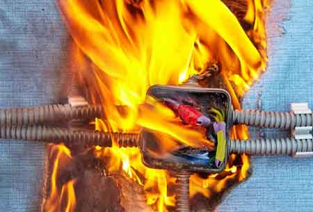
This dangerous event can result in power outages, damaged appliances, or even fires. By understanding the types of short circuits, their causes, detection methods, and prevention strategies, we can greatly reduce the risks. When studying short circuits, it is helpful to first understand the principles of basic electricity, as the same laws of voltage, current, and resistance explain why faults occur.


Causes of Short Circuits

There are several reasons why a short circuit may occur. Common causes include faulty appliance wiring, loose wire connections, and damaged insulation on wires. These issues can lead to current flowing through an unintended path, creating a short circuit.

Short circuits happen for many reasons, ranging from everyday wear to unusual accidents:

  • Damaged or faulty wiring – Insulation breakdown from age or overheating.

  • Water or moisture ingress – Flooding, leaks, or humidity can allow current to bypass insulation.

  • Pest damage – Rodents chewing wiring can strip insulation and create direct shorts.

  • Mechanical damage – Nails, drilling, or physical stress on cables.

  • Corrosion in connections – Loose or corroded joints create hot spots and unintended paths.

  • Appliance defects – Internal failures in motors, compressors, or electronics.

  • Ground faults vs. short circuits – A short is current between conductors, while a ground fault involves current leaking to earth.

  • Overload vs. short – Overload is too much current for too long; a short is a sudden surge with very low resistance.


Detection and Symptoms

Detecting a short circuit can be challenging, but some common signs may indicate its presence. Detecting a short circuit can be difficult, but common warning signs include:

  • Frequent tripping of breakers or GFCIs

  • Flickering or dimming lights

  • Buzzing or crackling sounds in outlets

  • Burning smells or discolored outlets

  • Damaged insulation or melted wires

For diagnosis, electricians use multimeters, insulation testers (meggers), clamp meters, and thermal imaging cameras to isolate fault locations. Tracers can also help locate hidden shorts inside walls. In three-phase systems, a fault between conductors can cause even greater hazards, making it essential to understand how three-phase electricity behaves under fault conditions. Ground faults are often confused with shorts, but a true electrical fault may involve multiple types of abnormal current flow.


Theory of a Short Circuit

A short circuit illustrates Ohm’s Law (V = I × R): when resistance (R) drops close to zero, current (I) increases dramatically. This sudden fault current stresses wiring, overheats insulation, and can exceed equipment ratings. That’s why time-current curves, protective relays, and properly sized conductors are crucial for safety. Protective devices are designed to limit current and prevent excessive electrical resistance heating that can trigger a fire.


Prevention

Prevention is key to safety. Prevention is the most effective protection. Strategies include:

  • Installing arc fault circuit interrupters (AFCIs) to detect dangerous arcs.

  • Using fuses, breakers, and GFCIs for fault interruption.

  • Adding surge protectors to handle transient spikes.

  • Ensuring proper conductor sizing and insulation quality.

  • Using protective relays and redundancy in industrial systems.

  • Regular inspections of cords, outlets, and panels.

Modern codes, such as the National Electric Code (NEC), the Canadian Electric Code, and IEC standards, all require specific protection and device ratings to reduce hazards.


Dangers of Short Circuits

Short circuits can pose significant risks to both people and property. They are among the most dangerous faults:

  • Fire hazards – Sparks and overheated wires ignite flammable materials.

  • Electric shock – Fault currents may flow through people during contact.

  • Equipment damage – Motors, appliances, and electronics can be severely damaged or destroyed.

For example, a refrigerator's shorted compressor can ignite nearby insulation, while an industrial panel's short can trip upstream breakers, causing outages and costly downtime. They are one of the many dangers of electricity that electricians must guard against through the use of insulation, grounding, and protective equipment.


How To Repair

If you suspect a short in the power system, it's crucial to address the issue immediately. If you suspect a short:

  1. Shut off the power at the breaker or unplug devices.

  2. Inspect outlets, cords, and panels for visible damage.

  3. Use diagnostic tools to isolate the faulted loop.

  4. Replace damaged wires or devices.

  5. If uncertain, consult a licensed electrician — shorts are not DIY-friendly.


Difference Between a Short Circuit and an Open Circuit

While both short circuits and open circuits involve disruptions in normal functioning, they are fundamentally different. A short occurs when the current flows through an unintended path, resulting in a sudden surge in current. In contrast, an open path is a break in its continuity, which stops the flow of current altogether. Both situations can cause problems in your system and should be addressed promptly.


Frequently Asked Questions


Can a short circuit happen in a GFCI outlet?

Yes. GFCIs protect against ground faults, but not all types of shorts. Breakers and fuses are still required.


How often should wiring be inspected?

Residential wiring should be inspected every 5–10 years, or immediately if signs of overheating or frequent breaker trips are observed.


What is the difference between a ground fault and a short circuit?

A ground fault involves current flowing into earth, while a short occurs between conductors. Both are hazardous.

Understanding shorts — their causes, detection, prevention, and associated risks — is crucial for safeguarding people and property. Regular inspections, proper protection, and adherence to codes all reduce hazards. If you suspect a short, act immediately and contact a qualified electrician.


Related Articles


Related News

What is Considered High Voltage? HV Applications Explained

What is considered high voltage? Per IEC/IEEE, voltages above 1 kV AC or 1.5 kV DC; linked to insulation coordination, arc-flash risk, transmission lines, substations, switchgear ratings, clearance/creepage distances, and dielectric breakdown in power systems.


What Is Considered High Voltage?

Voltages above 1 kV AC or 1.5 kV DC are classed as high voltage per IEC/IEEE in power systems.

✅ IEC/IEEE: >1 kV AC or >1.5 kV DC thresholds

✅ Categories: MV, HV, EHV, UHV in power transmission

✅ Impacts insulation, clearance, arc-flash, switchgear ratings


What is Considered High Voltage?

In the world of electrical engineering, understanding voltage levels is crucial. So you might be asked to define high voltage. But what is considered HV? This article explores the definition, classification, and applications of HV and the safety concerns and precautions that come with it. For foundational context, the concept of voltage underpins how these levels are defined and compared across systems.


According to the International Electrotechnical Commission (IEC), HV is typically defined as any voltage above 1000 volts for alternating current (AC) systems and 1500 volts for direct current (DC) systems. However, the term "HV" can also refer to voltages as low as 50 volts in some safety regulations, depending on the context. For example, the US Occupational Safety and Health Administration (OSHA) defines HV as 600 volts or higher in their safety guidelines. Standards often reference nominal voltage values that guide equipment ratings, insulation clearances, and test criteria in practice.

High voltage systems are essential in electric power transmission and distribution, allowing electricity to be transported over long distances with minimal energy loss. Power lines, transmission lines, and transformers all play a role in the power transmission and distribution process. Transformers are used to step up or down voltage levels, depending on whether the electricity is transported over long distances or distributed to end-users. At the point of use, networks step down to low voltage levels suitable for residential and commercial equipment before final delivery.

Voltage classification is a method for organizing voltages based on their range. There are four primary classifications of voltage levels: low (LV), medium  (MV), HV, and extra HV (EHV). Ultra HV (UHV) is another classification for exceptionally high voltages, typically used in long-distance power transmission projects. In distribution grids, medium voltage tiers bridge the gap between long-distance transmission and local feeders in a coordinated hierarchy.

Insulation is a crucial aspect of HV systems, as it prevents electrical current from leaking and causing short circuits, equipment damage, or even fires. Different types of insulation are used depending on the voltage level and application, such as air, gas, oil, or solid materials like plastics and ceramics. For clarity on terminology used in insulation, dielectric strength, and creepage distances, consult common electricity terms that standardize communication across projects.

HV circuits and equipment, such as transformers and switchgear, are designed to handle higher voltages safely and efficiently. These devices are essential components of power distribution networks and are subject to strict design, manufacturing, and testing standards to ensure reliability and safety.

Working with high voltage circuits presents several electrical hazards, such as electric shock, arc flash, and fires. To mitigate these risks, electrical safety measures must be put in place. Workers with HV equipment must follow safety procedures and use appropriate personal protective equipment (PPE), such as insulated gloves, safety glasses, and arc flash suits. Comprehensive electricity safety programs integrate procedures, labeling, lockout/tagout, and training to reduce incident rates.

So, what is considered high voltage? As mentioned earlier, the IEC defines HV as 1000 volts for AC and 1500 volts for DC. However, some safety regulations might consider voltages as low as 50 or 600 volts as HV.

HV is used in power transmission and distribution to transport electricity efficiently over long distances. Transmission lines, transformers, and other equipment are designed to handle HVs and are integral to power distribution networks.

Safety concerns associated with HV systems include electric shock, arc flash, and fires. Proper safety procedures and protective equipment are necessary to minimize these risks. Understanding the broader dangers of electricity helps contextualize HV-specific risks and informs mitigation strategies.

Transformers handle HV levels by stepping up or stepping down the voltage, allowing for efficient power transmission and distribution. They are designed to withstand HV stresses and are subject to rigorous testing and standards.

Various types of insulation are needed for HV applications, including air, gas, oil, and solid materials like plastics and ceramics. The choice of insulation depends on the level and specific application requirements.

The different classifications of voltage levels include low, medium, HV, extra HV, and ultra HV. These classifications help categorize voltage ranges for various applications and safety standards.

When working with HV equipment, workers should follow safety procedures, use appropriate personal protective equipment, and undergo regular training to stay updated on best practices and safety guidelines.

In conclusion, understanding what is considered HV is crucial for electrical systems' safe and efficient operation. HV plays a vital role in power transmission and distribution, allowing electricity to be transported over long distances with minimal losses. Proper insulation, transformers, and other equipment are designed to handle HV levels and ensure the reliability of the electrical infrastructure. Safety concerns associated with HV systems must be addressed through stringent safety procedures, protective equipment, and worker training. We can maintain a safe and efficient electrical infrastructure by adhering to these guidelines and understanding the importance of classifications.


High, Extra-High and Ultra-HV Classifications

High, extra-high, and ultra-high voltage classifications are categories used to define the levels within electrical systems, particularly in power transmission and distribution networks. These classifications help standardize the design, manufacturing, and operation of electrical equipment and ensure safety and efficiency.


High Voltage (HV):

HV is typically defined as levels between 1000 volts (1 kV) and 100,000 volts (100 kV) for alternating current (AC) systems and between 1500 volts (1.5 kV) and 100,000 volts (100 kV) for direct current (DC) systems. HV systems are commonly used in electric power transmission and distribution networks, substations, and industrial facilities. HV allows for efficient power transmission over long distances while reducing energy loss due to resistance.


Extra-High Voltage (EHV):

Extra-high voltage refers to levels above 100,000 volts (100 kV) and up to 300,000 volts (300 kV) for AC systems and between 100,000 volts (100 kV) and 800,000 volts (800 kV) for DC systems. EHV systems are primarily used for long-distance power transmission, where higher levels reduce energy losses even further. EHV lines and equipment require specialized design, manufacturing, and maintenance to ensure safety, reliability, and efficiency. The use of extra-high voltage is also associated with more stringent safety protocols and larger right-of-way requirements for transmission lines.


Ultra-High Voltage (UHV):

Ultra-high voltage classification is designated for levels above 300,000 volts (300 kV) for AC systems and above 800,000 volts (800 kV) for DC systems. UHV systems are used in large-scale power transmission projects that aim to transmit massive amounts of electricity over very long distances with minimal losses. These projects typically connect major power generation sources, such as hydroelectric or nuclear plants, to far-off load centers or densely populated urban areas. As a result, UHV systems demand the highest level of engineering expertise, rigorous testing, and specialized equipment to ensure their safe and efficient operation.


Related Articles

View more

What is a Potentiometer?

A potentiometer is a variable resistor that adjusts voltage in a circuit. It’s used for controlling electrical devices like volume knobs, sensors, and dimmers. Potentiometers regulate current flow by varying resistance, making them essential in analog electronic applications.


What is a Potentiometer?

A potentiometer is a type of adjustable resistor used to control voltage or current in an electrical circuit.

✅ Adjusts resistance to control voltage in circuits

✅ Commonly used in audio controls and sensors

✅ Essential for analog signal tuning and regulation

At its core, a potentiometer functions as a variable resistor. By moving the wiper (a movable terminal) across a resistive element, the device varies the output voltage. Depending on the position of the wiper, varying amounts of resistance are introduced into the circuit, thereby adjusting the current flow.

When the wiper moves along the resistive track, it adjusts the total resistance in the circuit, which controls the flow of current. To learn more, see our guide on Electrical Resistance.

A potentiometer acts as an adjustable Voltage divider, splitting the input voltage proportionally between two output terminals based on the wiper’s position.

This relationship is governed by Ohm’s Law Formula, which states that voltage equals current multiplied by resistance (V = IR).

As shown in Figure 6-8, the basic construction of a potentiometer includes:

  • A resistive track (usually carbon, cermet, or wire wound)

  • A movable wiper

  • Three terminals (two fixed, one connected to the wiper)

This setup enables the potentiometer to function as both a voltage divider and a simple variable resistor.


Fig. 6-8 Construction geometry of a potentiometer


Types of Potentiometers

Potentiometers come in several forms, each designed for specific applications:

A potentiometer is considered a variable resistor, one of several important types covered in our guide to Types of Resistors.


Rotary Potentiometer

The most common type, rotary potentiometers, adjust resistance through the rotation of a knob. These are frequently found in volume controls, light dimmers, and measuring instruments. The resistive track inside a potentiometer is made from materials that partially conduct electricity, such as carbon or cermet. For more on conductive materials, see Conductor of Electricity.


Figure 6-9 illustrates the typical circuit symbol for a rotary potentiometer.


Linear Potentiometer (Slide Potentiometer)

Instead of rotating, a linear potentiometer, often referred to as a slide potentiometer, adjusts by sliding a control lever. These are widely used in audio mixers and precision instruments where fine, linear adjustments are needed.


Audio Taper Potentiometer

In audio equipment, human hearing sensitivity is non-linear. Audio taper potentiometers adjust resistance logarithmically to provide a natural, smooth volume change that matches human perception.

Note: If you use a linear-taper potentiometer for audio volume control, the sound may seem to jump suddenly instead of increasing smoothly.


Digital Potentiometer

Digital potentiometers, also known as "digipots," are electronically controlled rather than manually adjusted. They find use in automatic tuning circuits, programmable amplifiers, and microcontroller applications.


Rheostat (Variable Resistor)

Although technically a type of potentiometer, a rheostat uses only two terminals: one fixed terminal and the wiper. It is optimized to control current rather than voltage. Rheostats are commonly used in applications like motor speed control and light dimming.


Practical Applications of Potentiometers

Potentiometers are found in a wide range of everyday and industrial applications:

  • Audio Equipment: Volume and tone controls on stereos and guitars

  • Automobiles: Throttle position sensors, dashboard dimmers

  • Industrial Controls: Machinery speed adjustments

  • Consumer Electronics: Game controller joysticks

  • Laboratory Equipment: Calibration and fine adjustments

Potentiometers are versatile components used in both AC and DC electrical systems, from audio controls to automotive sensors.

Their ability to fine-tune voltage and resistance makes them essential in both analog and digital systems.


How to Test a Potentiometer

Testing a potentiometer is straightforward:

  1. Disconnect power to the circuit.

  2. Use a multimeter set to measure resistance (ohms).

  3. Connect the multimeter probes to the outer two terminals to measure total resistance.

  4. Measure between the wiper and one outer terminal; adjust the control and observe the changing resistance.

Consistent, smooth changes confirm proper operation. Jumps or dead spots may indicate a worn or faulty potentiometer.

A potentiometer is a simple but versatile component that provides adjustable control over voltage or resistance in a circuit. Whether used in audio systems, automotive sensors, or industrial machinery, its importance in electronic design and control systems is undeniable.

Understanding the various types and practical applications of potentiometers can help in selecting the appropriate device for a specific task.

For readers seeking a broader understanding of basic electrical principles, visit our overview of Electricity Fundamentals.


Frequently Asked Questions


What is the difference between a potentiometer and a rheostat?

A potentiometer typically acts as a voltage divider with three terminals, while a rheostat uses only two terminals to control current.


Where are potentiometers commonly used?

Potentiometers are used in volume controls, sensors, gaming controllers, industrial equipment, and calibration tools.


How does a potentiometer adjust voltage?

By moving the wiper across the resistive track, a potentiometer divides the input voltage proportionally between the two output terminals, adjusting the output voltage.


Related Articles


View more

What is Electrical Resistance?

Electrical resistance is the measure of how much a material opposes the flow of electric current. Measured in ohms (Ω), it affects voltage, limits current, and plays a vital role in circuit function, energy loss, and power distribution.


What is Electrical Resistance?

Electrical resistance is a key concept in electronics that limits the flow of electricity through a conductor.

✅ Measured in ohms (Ω) to indicate opposition to current flow

✅ Affects voltage, current, and overall power efficiency

✅ Essential in designing safe and effective electrical circuits


Electrical Resistance is an electrical quantity that measures how a device or material reduces the flow of electric current through it. The resistance is measured in units of ohms (Ω). If we make an analogy to water flow in pipes, the resistance is greater when the pipe is thinner, so the water flow is decreased.

Electrical Resistance is a measure of the opposition that a circuit offers to the flow of electric current. You might compare it to the diameter of a hose. In fact, for metal wire, this is an excellent analogy: small-diameter wire has high resistance (a lot of opposition to current flow), while large-diameter wire has low resistance (relatively little opposition to electric currents). Of course, the type of metal makes a difference, too. Iron wire has higher resistance for a given diameter than copper wire. Nichrome wire has still more resistance.

Electrical resistance is the property of a material that opposes the flow of electric current. The resistance of a conductor depends on factors such as the conducting material and its cross-sectional area. A larger cross-sectional area allows more current to flow, reducing resistance, while a smaller area increases it. The unit of electrical resistance is the ohm (Ω), which measures the degree to which a material impedes the flow of electric charge. Conductors with low resistance are essential for efficient electrical systems.


What causes electrical resistance?

An electric current flows when electrons move through a conductor, such as a metal wire. The moving electrons can collide with the ions in the metal. This makes it more difficult for the current to flow, and causes resistance.


Why is electrical resistance important?

Therefore, it is sometimes useful to add components called resistors into an electrical circuit to restrict the flow of electricity and protect the components in the circuit. Resistance is also beneficial because it allows us to shield ourselves from the harmful effects of electricity.

The standard unit of resistance is the ohm. This is sometimes abbreviated by the upper-case Greek letter omega, resembling an upside-down capital U (Ω). In this article, we'll write it out as "ohm" or "ohms."

You'll sometimes hear about kilohms, where 1 kilohm = 1,000 ohms, or about megohms, where 1 megohm = 1,000 kilohms = 1,000,000 ohms.

Electric wire is sometimes rated for resistivity. The standard unit for this purpose is the ohm per foot (ohm/ft) or the ohm per meter (ohm/m). You may also encounter the unit of ohms per kilometre (ohm/km). 

When an IV is placed across 1 ohm of resistance, assuming the power supply can deliver an unlimited number of charge carriers, there will be a current of 1 A. If the re­sistance is doubled, the current is halved. If the resistance is cut in half, the current doubles. Therefore, the current flow, for a constant voltage, is inversely proportional to the resistance. 

Typically, four-terminal resistors are used to measure current by measuring the voltage drop between the voltage terminals with current flowing through the current terminals. These standards, designed for use with potentiometers for precision current measurement, correspond in structure to the shunts used with millivoltmeters for current measurement with indicating instruments. Current standards must be designed to dissipate the heat they develop at rated current, with only a small temperature rise. They may be oil- or air-cooled; the latter design has a much greater surface area, as heat transfer to still air is less efficient than to oil. An air-cooled current standard with a 20 μω resistance and 2000 A capacity has an accuracy of 0.04%. Very low-resistance oil-cooled standards are mounted in individual oil-filled containers, provided with copper coils through which cooling water is circulated and with propellers to provide continuous oil motion.

Related Articles


View more

What is a Multimeter?

A multimeter is an electrical testing instrument used to measure voltage, current, and resistance. Essential for electricians, engineers, and hobbyists, this device combines multiple diagnostic tools into one for troubleshooting circuits and ensuring safety.


What is a Multimeter?

A multimeter is a versatile electrical measurement tool that combines several functions into one device for testing and troubleshooting circuits.

✅ Measures voltage, current, resistance, and continuity

✅ Essential for electrical safety and diagnostic accuracy

✅ Used by electricians, engineers, and electronics hobbyists

This article will explore the features, types, and uses of multimeters, as well as answer some common questions about this indispensable tool.

Multimeters come in two primary forms: digital (DMMs) and analog multimeters. DMMs have a digital display, making them easy to read and providing more accurate electrical measurements. In contrast, analog meters use a needle on a dial to indicate the measured value. While digital multimeters are generally more popular due to their precision and ease of use, analog MMs can be useful for observing trends or changes in measurement. To fully understand what a multimeter is, it is helpful to place it within the broader category of electrical test equipment, which includes tools designed for measuring, diagnosing, and maintaining electrical systems.


Types of Multimeters

Different types of multimeters are designed to meet specific needs, from basic household troubleshooting to advanced industrial testing. Each type has unique strengths and limitations. Multimeters come in several forms:

  • Digital Multimeters (DMMs) provide accurate digital readouts, often featuring auto-ranging, data hold, and true RMS capability for measuring complex AC waveforms. Resolution is expressed in digits or counts (e.g. 4½-digit, 20,000-count meters).

  • Analog Multimeters: Use a moving needle to display values. While less precise, they are helpful for observing trends, fluctuations, or slowly changing signals. Their sensitivity is often expressed in ohms per volt (Ω/V).

  • Clamp Multimeters: Measure current without breaking the circuit by clamping around a conductor. These are widely used in electrical maintenance and HVAC applications.

When comparing digital and analog devices, our guide to analog multimeters highlights how needle-based displays can still be useful for observing trends in circuits.


Comparison of Multimeter Types

Type Accuracy Features Cost Best For
Digital Handheld High Autoranging, RMS Affordable Everyday troubleshooting and field service
Analog Moderate Needle display Low Observing signal trends and teaching basics
Clamp Meter High Non-contact current Moderate Measuring high current safely in maintenance work
Bench Multimeter Very High High resolution Expensive Precision testing, R&D, and calibration labs


Key Technical Concepts

One of the primary functions of a multimeter is to measure voltage. Voltage measurements can be made on both alternating current (AC) and direct current (DC) sources. To do this, the multimeter is connected to the circuit under test using red and black test probes. Therefore, selecting the appropriate measuring range and observing safety precautions when dealing with high voltages is essential. Learning how to use a digital multimeter provides step-by-step instruction for safely measuring voltage, current, and resistance.

Understanding the specifications of a multimeter helps ensure accurate and safe measurements:

  • Input Impedance: High input impedance (commonly 10 MΩ) prevents the meter from disturbing the circuit under test.

  • Burden Voltage: When measuring current, internal shunt resistors create a small voltage drop that can affect sensitive circuits.

  • Resolution and Accuracy: Resolution defines the smallest measurable increment; accuracy indicates how close a reading is to the true value.

  • True RMS vs Average Responding: True RMS meters provide accurate readings of non-sinusoidal waveforms, unlike average-responding meters.

  • Fuse Protection and Safety Ratings: Quality multimeters include internal fuses and comply with IEC safety categories (CAT I–CAT IV), which define safe voltage levels for various environments.

  • Probes and Ports: Good test leads, properly rated ports, and accessories are essential for both safety and accuracy.


Using a Multimeter

Multimeters can measure more than just voltage, current, and resistance. Depending on the model, they may also include additional functions that expand their usefulness, including:

  • Voltage (AC/DC): Connect probes across the circuit. Select the correct range and observe safety precautions at high voltages.

  • Current (AC/DC): Insert the meter in series with the circuit. Use the correct current jack and range to avoid fuse damage.

  • Resistance: Connect probes across the component with power removed.

  • Continuity: A beeping function confirms a complete connection between two points.

  • Capacitance and Frequency: Many modern DMMs measure these directly.

  • Diode Test and Temperature: Specialized modes test semiconductors or use thermocouples to measure heat.

Each function requires accurate probe placement, proper range selection, and adherence to safety guidelines. Because multimeters are often the first line of defence in electrical troubleshooting, they play a central role in diagnosing faults before moving on to more specialized instruments.


Choosing a Multimeter

The best multimeter for your needs depends on what you plan to measure, how often you’ll use it, and the environment where it will be used. Key factors include:

  • Accuracy and Resolution (e.g. ±0.5% vs ±2%)

  • Safety Ratings (IEC CAT I–IV, with higher CAT numbers for higher-energy environments)

  • Features (autoranging, backlight, data logging, connectivity such as USB or Bluetooth)

  • Build Quality (durability, insulated leads, protective case)

  • Application Needs (bench meters for labs vs handheld DMMs for field use)


Applications and Use Cases

Due to their versatility, multimeters are utilized across various industries by both professionals and hobbyists. Common applications include:

  • Household and industrial electrical troubleshooting

  • Electronics prototyping and repair

  • Automotive and HVAC system diagnostics

  • Power supply and battery testing

  • Field service and maintenance

In industrial settings, understanding what is a multimeter goes hand in hand with broader practices like industrial electrical maintenance, where accuracy and safety are critical.


Advantages and Limitations

Like any tool, multimeters have strengths that make them invaluable, as well as limitations that users must understand.

Advantages:

  • Combines a voltmeter, an ammeter, an ohmmeter, and more into one device

  • Affordable and widely available

  • Fast, versatile, and portable

Limitations:

  • Accuracy is lower than specialized laboratory instruments

  • Burden voltage can affect sensitive circuits

  • Incorrect use may damage the meter or the circuit

For preventive strategies, multimeters complement other tools covered in preventive maintenance training, ensuring equipment remains reliable and downtime is minimized.


Safety and Standards

Safe multimeter operation depends on both correct technique and the proper use of equipment. Following these precautions reduces risks and ensures accurate results. Safe multimeter use requires:

  • Using the correct range and function for each measurement

  • Ensuring probes and leads are rated for the environment (CAT I–IV)

  • Observing overvoltage ratings and fuse protection

  • Avoiding direct contact with live circuits

  • Regular calibration and inspection for damaged leads or cases

Failure to follow safety precautions can lead to inaccurate readings, blown fuses, or electric shock. Standards such as NFPA 70B 2023 emphasize the importance of testing equipment like multimeters as part of a comprehensive electrical maintenance program.


History and Terminology

The word “multimeter” reflects its ability to measure multiple quantities. Early versions were known as Volt-Ohm-Meters (VOMs) or Avometers (after the original AVO brand), first popularized in the early 20th century. Digital multimeters largely replaced analog models in the late 20th century; however, analog meters remain useful for certain applications.


Frequently Asked Questions


What is the input impedance of a multimeter?

It refers to the resistance the meter presents to the circuit. Higher impedance prevents measurement errors and reduces loading on the circuit.


Why is True RMS important?

True RMS meters accurately measure non-sinusoidal signals, which are common in modern electronics, while average-responding meters can yield misleading results.


Can using a multimeter damage a circuit?

Yes, incorrect range selection, probe placement, or exceeding current ratings can damage circuits or blow fuses inside the meter.


How accurate are digital multimeters?

Typical handheld models are accurate within ±0.5% to ±2%. Bench models achieve significantly higher accuracy, making them suitable for calibration labs.


What safety rating should I look for?

For household electronics, CAT II is often sufficient. For industrial or utility work, CAT III or CAT IV-rated meters are required.

A multimeter is a versatile instrument that combines measurement functions into a single, indispensable tool for electrical diagnostics. By understanding the types, functions, technical specifications, and safety standards of multimeters, users can select the right one and use it effectively across various applications, including home, industrial, and laboratory settings.


Related Articles


View more

What is an Arc Fault?

An arc fault is a dangerous electrical discharge between conductors or to ground. It generates intense heat and light, often caused by damaged insulation, frayed wires, or loose connections, posing major electrical safety and fire hazards.


What is an Arc Fault?

An arc fault is an unintended electrical discharge that occurs when insulation or wiring fails, producing dangerous heat that can ignite fires and damage circuits.

✅ Caused by frayed wires or loose connections

✅ Produces intense heat and light energy

✅ Prevented by Arc Fault Circuit Interrupters (AFCIs)


Basic Protection Relay Training

Short Circuit Study Training

Request a Free Training Quotation


Understanding Arc Faults and Electrical Safety

An arc fault is a hazardous electrical event that can lead to severe consequences, including fires and substantial property damage. Understanding how faults occur, how to prevent them, and why protective measures like Arc Fault Circuit Interrupters (AFCIs) are essential can significantly improve home and workplace safety.

When electrical current jumps across a gap or an unintended path, it forms an electric arc. This arc generates extremely high temperatures—often exceeding 10,000°F—capable of igniting nearby insulation, wood framing, or other combustible materials. Faults are typically caused by damaged, frayed, or aging wiring, loose terminal connections, or punctured cables from nails and screws during construction. For more insight into advanced safety devices, learn how an arc fault interrupter breaker detects hazardous arcing and disconnects power before a fire can start.

Arc fault protection is especially important in areas where people live and spend time, such as family rooms, dining rooms, and living rooms, where electrical wiring runs behind walls containing materials such as wood framing or insulation that can easily ignite. Modern safety standards, as mandated by the National Electrical Code, require the installation of Arc Fault Circuit Interrupters (AFCIs) in these spaces to prevent fires caused by faults. When combined with Ground Fault Circuit Interrupters, which protect against electrical shock, AFCIs provide comprehensive protection against both fire and shock hazards in residential and commercial environments.


Types of Arc Faults

Arc faults can appear in different forms, each with its own risks and detection requirements:

  • Series Faults – Occur along a single conductor, usually from a broken wire or loose terminal. These arcs produce less current but can still ignite fires.

  • Parallel Faults – Form between two conductors (hot-to-neutral or hot-to-ground). These faults create higher current levels and more intense arcing.

  • Ground Faults – Happen when current leaks or shorts to a grounded surface, such as a metal outlet box or appliance casing. Explore how ground fault protection complements AFCIs by guarding against current leakage that could cause electric shock or parallel arc conditions.

Recognizing these types helps electricians and inspectors identify the right protection strategies and select appropriate AFCI devices. To see how fault current behavior impacts fault risks, review our explanation of available fault current and why accurate short-circuit studies are essential for system safety.


How AFCI Detection Works

AFCIs are intelligent safety devices designed to detect the unique electrical signatures of faults. They continuously monitor current waveforms and frequencies, distinguishing dangerous arcs from normal switching arcs (such as those produced by light switches or vacuum cleaners).

When an AFCI identifies an abnormal frequency pattern consistent with arcing, it trips the circuit within milliseconds—disconnecting power before the fault can ignite a fire. This advanced “signature detection” technology is required by modern safety codes and has saved countless lives and properties. For more insight into advanced safety devices, learn how an arc fault interrupter breaker detects hazardous arcing and disconnects power before a fire can start.


Limitations and Nuisance Tripping

While AFCIs are highly effective, they can occasionally cause nuisance tripping. This occurs when the device misinterprets harmless electrical noise as a fault, typically triggered by motors, dimmers, or other electronic devices. Regular inspection, proper grounding, and updated AFCI models help minimize these false positives. If nuisance tripping persists, it’s advisable to have an electrician verify circuit wiring and device compatibility. To understand how electrical systems respond to fault conditions, refer to our detailed explanation of protective relay coordination, which ensures that circuit breakers isolate faults without disrupting unaffected circuits.


Code Requirements and Standards

Arc fault protection is mandated by both U.S. and Canadian electrical codes:

  • National Electrical Code (NEC 210.12) requires AFCI protection for all 120-volt, single-phase, 15- and 20-amp branch circuits supplying living areas such as bedrooms, family rooms, dining rooms, and similar spaces.

  • Canadian Electrical Code (CEC Section 26) similarly mandates AFCI in dwelling units.

  • IEEE 1584 provides calculation guidelines for flash hazards in industrial power systems, complementing residential and commercial fault safety standards.

Following these standards ensures compliance and dramatically reduces fire risks across residential, commercial, and industrial applications.


Statistics and Case Studies

According to the U.S. Consumer Product Safety Commission (CPSC), electrical fires cause over 51,000 residential fires annually, resulting in more than 500 deaths and $1.3 billion in property damage. Studies show that AFCI protection can prevent more than half of these incidents, highlighting its critical role in modern electrical safety systems.


Emerging Technologies in Arc Fault Detection

New generations of AFCIs utilize microprocessors and artificial intelligence to enhance accuracy and minimize false trips. These smart devices analyze waveform patterns with greater precision, detecting high-impedance arcs and subtle irregularities. Future technologies may integrate predictive analytics and IoT monitoring to diagnose potential faults before they become hazards. Finally, explore comprehensive methods of electrical surge protection, which safeguard sensitive equipment from voltage spikes often linked to lightning events.


Common Causes of Arc Faults

  • Damaged or aging electrical wiring

  • Loose terminal connections in outlets or switches

  • Overloaded circuits or faulty appliances

  • Nails or screws penetrating electrical cables

  • Deteriorated insulation from heat, moisture, or rodents

Regular maintenance and periodic inspections by a licensed electrician are essential preventive measures.


Arc Fault vs Ground Fault vs Short Circuit

Fault Type Description Main Hazard Protection Device
Arc Fault Unintended arcing between conductors or within wiring Fire risk AFCI
Ground Fault Current flowing to ground unintentionally Electric shock GFCI
Short Circuit Direct contact between conductors High current / equipment damage Circuit Breaker

Understanding these differences helps ensure that electrical protection systems are properly matched to the specific hazards they are intended to address.


Frequently Asked Questions


Why does my AFCI keep tripping?

Often due to electronic interference, shared neutrals, or actual wiring issues. Replace outdated AFCIs and consult a professional if tripping persists.


Can I retrofit AFCIs into older panels?

Yes. AFCI breakers can replace standard breakers in most modern panels. Have a qualified electrician confirm compatibility before installation.


Are AFCIs required everywhere?

While required in most living spaces, some regions exempt areas like garages or unfinished basements. Check the NEC or CEC requirements for your jurisdiction.


Related Articles


View more

What is a Voltmeter?

What is a voltmeter? A voltmeter is an electrical measuring instrument used to determine voltage across circuit points. Common in electronics, engineering, and power systems, it ensures accuracy, safety, and efficiency when monitoring current and diagnosing electrical performance.


What is a Voltmeter?

A Voltmeter provides a method to accurately measure voltage, which is the difference in electric potential between two points in a circuit, without changing the voltage in that circuit. It is an instrument used for measuring voltage drop.

✅ Ensures accurate voltage measurement for safety and performance

✅ Used in electrical engineering, electronics, and power systems

✅ Helps diagnose faults and maintain efficient operation

Electrical current consists of a flow of charge carriers. Voltage, also known as electromotive force (EMF) or potential difference, manifests as "electrical pressure" that enables current to flow. Given an electric circuit under test with a constant resistance, the current through the circuit varies directly in proportion to the voltage across the circuit. A voltmeter measures potential difference, which directly relates to Ohm’s Law, the fundamental equation connecting voltage, current, and resistance in circuits.

A voltmeter can take many forms, from the classic analog voltmeter with a moving needle to modern instruments like the digital voltmeter (DVM) or the versatile digital multimeter. These tools are essential for measuring electrical values in electronic devices, enabling technicians to measure voltage, current, and resistance with precision and accuracy. While analog units provide quick visual feedback, digital versions deliver more precise measurements across wider voltage ranges, making them indispensable for troubleshooting and maintaining today’s complex electrical systems.

A voltmeter can be tailored to have various full-scale ranges by switching different values of resistance in series with the microammeter, as shown in Fig. 3-6. A voltmeter exhibits high internal resistance because the resistors have large ohmic values. The greater the supply voltage, the larger the internal resistance of the voltmeter because the necessary series resistance increases as the voltage increases. To understand how a voltmeter works, it helps to first review basic electricity, as voltage, current, and resistance form the foundation of all electrical measurements.


Fig 3-6. A simple circuit using a microammeter (tA) to measure DC voltage.


A Voltmeter, whether digital or analog, should have high resistance, and the higher the better. You don't want the meter to draw a lot of current from the power source. (Ideally, it wouldn't draw any current at all.) The power-supply current should go, as much as possible, towards operating whatever circuit or system you want to use, not into getting a meter to tell you the voltage. A voltmeter is commonly used to measure voltage drop across conductors or devices, helping electricians ensure circuits operate efficiently and safely. For quick calculations, a voltage drop calculator provides accurate estimates of conductor losses based on length, size, and current. Understanding the voltage drop formula allows engineers and technicians to apply theoretical principles when designing or troubleshooting electrical systems.

Also, you might not want to keep the voltmeter constantly connected in parallel in the circuit. You may need the voltmeter for testing various circuits. You don't want the behavior of a circuit to be affected the moment you connect or disconnect the voltmeter. The less current a voltmeter draws, the less it affects the behavior of anything that operates from the power supply. Engineers often ask: What is a voltmeter?  They use a voltmeter in power system analysis, where accurate voltage readings are crucial for ensuring safety, reliability, and optimal performance.

Alternative types of voltmeters use electrostatic deflection, rather than electromagnetic deflection, to produce their readings. Remember that electric fields produce forces, just as magnetic fields do. Therefore, a pair of electrically charged plates attracts or repels each other. An electrostatic type utilizes the attractive force between two plates with opposite electric charges or a large potential difference. A voltmeter is used to measure the potential difference. Figure 3-7 portrays the functional mechanics of an electrostatic meter. It constitutes, in effect, a sensitive, calibrated electroscope. A voltmeter draws essentially no current from the power supply. Nothing but air exists between the plates, and air constitutes a nearly perfect electrical insulator. A properly designed electrostatic meter can measure both AC voltage and DC voltage. However, the meter construction tends to be fragile, and mechanical vibration can influence the reading.


Fig 3-7. Functional drawing of an electrostatic voltmeter movement.


It's always good when a voltmeter has a high internal resistance. The reason for this is that you don't want the voltmeter to draw a significant amount of current from the power source. This cur­rent should go, as much as possible, towards working whatever circuit is hooked up to the supply, and not just into getting a reading of the voltage. Additionally, you may not want or need to have the voltmeter constantly connected in the circuit; instead, you might need it for testing various circuits. You don't want the behavior of the circuit to be affected the instant you connect the voltmeter to the supply. The less current a voltmeter draws, the less it will affect the behavior of anything that is working from the power supply.

If you connect an ammeter directly across a source of voltage, a battery, the meter needle will deflect. In fact, a milliammeter needle will probably be "pinned" if you do this with it, and a microammeter might well be wrecked by the force of the needle striking the pin at the top of the scale. For this reason, you should never connect milli-ammeters or micro-ammeters directly across voltage sources. An ammeter, perhaps with a range of 0-10 A, may not deflect to full scale if it is placed across a battery; however, it's still a bad idea to do so, as it will rapidly drain the battery. Some batteries, such as automotive lead-acid cells, can explode under these conditions. This is because all ammeters have low internal resistance. They are designed that way deliberately. They are meant to be connected in series with other parts of a circuit, not right across the power supply. Because voltage is inseparable from current, learning what is current electricity provides deeper insight into why voltmeters are vital diagnostic tools.

But if you place a large resistor in series with an ammeter, and then connect the ammeter across a battery or other type of power supply, you no longer have a short cir­cuit. The ammeter will give an indication that is directly proportional to the voltage of the supply. The smaller the full-scale reading of the ammeter, the larger the resistance needed to get a meaningful indication on the meter. Using a microammeter and a very large resistor in series, it can be devised that draws only a small current from the source.

So, What is a Voltmeter? In summary, a voltmeter is a fundamental instrument for electrical work, allowing professionals and students to accurately measure voltage and understand circuit behaviour. Whether using an analog or digital design, voltmeters and multimeters provide precise insights that support safety, efficiency, and reliable performance in electrical systems.

Related Articles


View more

Sign Up for Electricity Forum’s Newsletter

Stay informed with our FREE Newsletter — get the latest news, breakthrough technologies, and expert insights, delivered straight to your inbox.

Electricity Today T&D Magazine Subscribe for FREE

Stay informed with the latest T&D policies and technologies.
  • Timely insights from industry experts
  • Practical solutions T&D engineers
  • Free access to every issue

Download the 2025 Electrical Training Catalog

Explore 50+ live, expert-led electrical training courses –

  • Interactive
  • Flexible
  • CEU-cerified