What is a Resistor?

By R.W. Hurst, Editor


what is a resistor

A resistor is an electronic component that limits or regulates the flow of electric current, manages voltage levels, and safeguards circuits in electrical and electronic devices, ensuring stable performance and preventing component damage.


What is a resistor?

A resistor is an electronic component designed to create electrical resistance in a circuit.

✅ Limits or regulates electric current flow in circuits

✅ Controls voltage levels for proper device operation

✅ Protects electrical and electronic components from damage

In electronic components and circuits, resistors play a crucial role. But what exactly is a resistor, and why are they so important? This comprehensive guide will explain the basics of resistors, explore different types and applications, and answer common questions related to their function and use. 

Their primary function is to control and limit the flow of electrical current, ensuring the proper operation of electronic devices and, in addition, introducing resistance to help maintain stable voltage and current levels in circuits, protecting sensitive components from damage due to excess current.


Electrical Resistance

Understanding electrical resistance is essential to grasping how resistors control current flow and protect sensitive components in circuits. The value of a resistor is determined by its electrical resistance, which is measured in ohms (Ω). Resistance is directly related to Ohm's law, a fundamental principle in electronics that states that the current (I) flowing through a conductor between two points is directly proportional to the voltage (V) across those points and inversely proportional to the resistance (R). In simpler terms, the equation V = I represents Ohm's law of R. Resistors work alongside capacitors and other components to regulate voltage and ensure stable performance in electronic devices. The unit of electrical resistance, the ohm (Ω), defines how much a resistor opposes the flow of electric current.

Various types of resistors are available, each with its own set of applications and characteristics. Some common resistor types include fixed resistors, variable resistors, carbon film resistors, metal foil resistors, metal oxide film resistors, and wire-wound resistors.

As the name suggests, fixed resistors have a fixed resistance value and are often used for general-purpose applications. Carbon film and metal film resistors are popular examples of fixed resistors, with the latter offering higher accuracy and stability. On the other hand, wire-wound resistors are constructed using a metal wire wrapped around a core, providing excellent heat dissipation and making them suitable for high-power applications.


Types of Resistors

Variable resistors, also known as potentiometers or rheostats, allow users to adjust the resistance manually. These components are typically used for fine-tuning and controlling various aspects of electronic circuits, such as volume or light intensity. Different types of resistors offer unique properties for specific applications, from precision electronics to high-power systems.

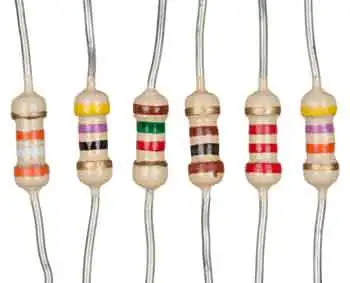
Resistor colour codes identify the value, tolerance, and sometimes the temperature coefficient of fixed resistors. The colour code consists of a series of coloured bands, with each colour representing a specific number. To read the colour code, you need to learn the number assigned to each colour and understand the sequence of bands.

The primary difference between fixed and variable resistors is the ability to adjust the resistance value. Fixed resistors have a predetermined resistance that cannot be changed, while variable resistors can be adjusted to obtain the desired resistance within a certain range.


Power Dissipation

Power dissipation is the heat a resistor generates when electrical current flows through it. This heat can affect the performance and reliability of a resistor and, in some cases, may cause damage to the component or the circuit. To prevent such issues, resistors are designed with a power rating, which indicates the maximum amount of power they can safely dissipate.

A resistor is integral to electronic circuits and can be found in virtually every electronic device. They come in various shapes, sizes, and materials to suit various applications. With their ability to control electrical current and maintain the stability of circuits, resistors play a vital role in the successful operation of electronic devices.


What is a resistor?

Resistors are essential electronic components that help regulate electrical current and voltage within circuits. Their various types and applications cater to different needs in the electronics world. Understanding resistors and their characteristics is crucial for anyone working with electronic circuits or looking to build their own devices.


Related Articles


Related News

What is Current Electricity?

Current electricity is the flow of electric charge through a conductor, usually as moving electrons. It powers devices in homes and industries. Driven by voltage, this flow enables the transfer of energy through wires, forming the basis of modern electrical systems.


What is Current Electricity?

Current electricity refers to the continuous movement of electric charges (typically electrons) through a conductor, driven by an electromotive force (EMF), or voltage.

✅ Describes the movement of electric charge through a conductor

✅ Powers electrical devices in homes, industries, and electronics

✅ Exists as direct current (DC) or alternating current (AC)

Current is defined as an electrical charge in motion. It consists of a flow of negatively charged electrons from atom to atom through a conductor in an electrical circuit. The external force that causes the electron current flow of electric charge is called the electromotive force (emf) or voltage.

When charges move through these wires, they generate different forms of energy, which can power devices and systems. One common type of current is alternating current (AC), where the direction of the charge flow periodically reverses. This movement of charges can be compared to water flowing through a pipe, where the electrical potential pushes the flow, making it essential for transporting energy efficiently across distances.


The Quantitative Definition

Electric current is defined as the rate of flow of electric charge:

I = Q / t

Where:

  • I is current in amperes (A)

  • Q is charge in coulombs (C)

  • t is time in seconds (s)

For example, a current of 1 ampere means 1 coulomb of charge flows per second through a given point in the circuit.


Types of Current: AC and DC

  • Direct Current (DC): Charge flows in one constant direction. Example: Batteries.

  • Alternating Current (AC): Charge reverses direction periodically. Example: Household wall outlets (typically 60 Hz in North America).


How Current Electricity Works

Electric current arises when free electrons move through a conductor. In metals, these electrons are loosely bound and can drift when a voltage is applied. This movement is like water flowing through a pipe — voltage acts as the pressure that pushes the electrons along.

Voltage sources such as batteries or generators create this pressure, known as electromotive force (emf). The electrons flow from the negative terminal (excess electrons) toward the positive terminal (electron deficiency).


Effects of Electric Current

Electric current produces multiple observable effects:

  • Magnetic effect: Current creates magnetic fields (used in motors and transformers).

  • Thermal effect: Electric current generates heat (used in heaters and toasters).

  • Chemical effect: In electrolysis, current causes chemical reactions.

These effects make current electricity essential for thousands of real-world applications.


Ohm’s Law and Resistance

Ohm’s Law defines the relationship between voltage (V), current (I), and resistance (R):

V = I × R

Where:

  • V is voltage in volts

  • I is current in amperes

  • R is resistance in ohms (Ω)

This relationship helps calculate circuit behavior and select the right components for safe and effective electrical design.


Measuring Current

Current is measured using devices such as:

  • Ammeter: Installed in series with a circuit to measure current directly.

  • Clamp meter: Measures current without disconnecting wires, using magnetic field sensing.

  • Multimeter: A general-purpose tool that can measure voltage, resistance, and current.


Real-World Applications

Current electricity is present in virtually every aspect of modern life:

  • Lighting systems

  • Household appliances

  • Industrial machinery

  • Electric vehicles

  • Cell phones and computers

  • Medical equipment

  • Power grids and transmission lines

It also flows in biological systems, such as ion currents in nerve cells and plasma currents in scientific and industrial applications.


Static vs. Current Electricity

Although both involve electric charges, static electricity refers to charges at rest, whereas current electricity refers to the motion of those charges. Static electricity may build up and discharge suddenly, but only current electricity performs continuous work, such as powering a device or generating heat.


Frequently Asked Questions


What is an example?

Examples of current electricity are starting a car, turning on a light, cooking on an electric stove, watching TV, shaving with an electric razor, playing video games, using a phone, charging a cell phone and more. 


Is current and electricity the same?

Current is a general characteristic of alternating current AC, like voltage and resistance. It's a name given to the flow of electrons (charge) through a medium. Electricity is a generic term used to describe the common flow of energy that powers all electrical devices. Current, in general, refers to any flow.


What are the two types of current electricity?

There are two different types of current in widespread use today. They are direct current, abbreviated DC, and alternating current, which is abbreviated AC. In a direct current, the electrons flow in one direction.

The electromotive force (emf) or voltage, as explained by Ohm's law, is created by a battery that consists of one positively charged and one negatively charged terminal. The negative terminal has an excess of electrons, while the positive terminal has a deficiency of electrons. When a conductor, in this case an electric light bulb, is connected to the two terminals of the battery, a flow of electrons occurs, producing both magnetic fields and an electric field. The positive terminal of the battery has a shortage of electrons and thus attracts electrons from the conductor. The negative terminal has an excess of free electrons to move, which repels electrons into the conductor.

Although "static" and "current" may seem different, they are really the same—both consist of electrical charges. Static electricity consists of electrons at rest on an insulated object and does little work. CE charge flows and does useful work. When static electricity is discharged, it is no longer static electricity — it is actually current electricity.

CE may also be classified as either direct current (DC) or alternating current (AC) based on the voltage source. Direct current voltage produces a constant flow of electrons in one direction only. Alternating current voltage produces a flow of positive and negative charge electrons in both directions, with varying magnitude. A battery is a common DC voltage source, while an electrical wall outlet is the most common AC voltage source (Figure 1).

Polarity identification (+ or -) and magnetic fields are one way to distinguish between a voltage source and a current source. Polarity can be identified on direct current circuits, but in alternating current circuits, the current continuously reverses direction; therefore, polarity cannot be identified. Additionally, it is essential to determine whether an electrical energy source generates alternating current or direct current. Many control and load components are designed to operate with a specific type of current. Operating the components with the wrong type of current or DC polarity can result in improper operation and/or permanent damage to the component.


Fig. 1. Current Electricity. Electrical charges moves.


Related Articles


View more

What is an Electrical Fault?

An electrical fault occurs when a system or piece of equipment departs from its normal operating state, resulting in abnormal current flow. This can result in overheating, equipment damage, or safety risks. Protective devices isolate faults to preserve safety and reliability.


What is an Electrical Fault?

An electrical fault is an abnormal condition in a power system or equipment. It happens when the current flowing through a circuit is partially or completely interrupted.

✅ Short circuits, ground faults, and overloads are common types

✅ Protective devices mitigate hazards and equipment damage

✅ Fault detection ensures system safety and reliability


Electrical faults can occur for various reasons, including equipment failure, environmental conditions, and human error. Some common causes of electrical faults include faulty wiring, damaged insulation, overloaded circuits, lightning strikes, power surges, and voltage fluctuations. 

  • Equipment issues: faulty wiring, broken insulation, overloaded circuits

  • Environmental conditions: moisture, lightning, dust, or tree contact

  • Human error: poor installation, neglect, or unsafe work practices

The most common fault categories include open-circuit faults, short-circuit faults, and ground faults. An open circuit fault occurs when a break in the circuit prevents current from flowing. A short circuit occurs when an unintended connection between two points allows an excessive amount of current to flow. A ground fault occurs when an unintended connection between the electrical circuit and the ground creates a shock hazard. Faults often relate to excessive current flow, which can be better understood through Ohm’s Law and its role in determining resistance, voltage, and current relationships.

A balanced fault is a condition in which all three phases of a three-phase system are shorted to ground or to each other. In this type of fault, the system remains balanced, and the fault current is limited. Understanding basic electricity is essential to grasp how faults disrupt the normal flow of current in a circuit.


Classifications of Electrical Faults

Electrical faults can be categorized into several groups to help engineers understand their causes and plan effective protective measures.

Transient vs. Permanent Faults: Transient faults, such as those caused by a lightning strike or temporary contact with a tree branch, clear on their own once the source is removed. Permanent faults, on the other hand, require repair before normal operation can resume, such as when insulation fails or a conductor breaks.

Symmetric vs. Asymmetric Faults: A symmetric fault affects all three phases of a system equally, and although rare, it can cause severe damage due to the high fault currents it generates. Asymmetric faults are far more common, involving one or two phases, and they create an unbalanced condition in the system.

Internal vs. External Faults: Internal faults occur within equipment, such as transformers, generators, or motors, often due to insulation breakdown or winding damage. External faults originate outside the equipment, caused by conditions such as storm damage, contact with foreign objects, or human error.


Types of Electrical Faults in Power Systems

A line-to-ground fault occurs when one of the conductors in a circuit comes in contact with the ground. This can happen due to faulty insulation, damaged equipment, or environmental conditions. A common example is a lightning strike creating a transient line-to-ground fault that trips breakers on a distribution system.

Other major types include:

  • Line-to-ground: conductor touches ground, causing shock risk

  • Open circuit: broken wires or components stop current flow

  • Phase fault: phases contact each other or ground

  • Short circuit: an unintended connection allows excessive current

  • Single-phase: limited to one phase, but still damaging

  • Arc fault: current jumps an air gap, creating sparks and fire risk

  • Balanced vs unbalanced: equal current in phases vs uneven distribution

Rodents chewing through insulation in attics or utility spaces often cause arc faults, showing how even small intrusions can lead to dangerous electrical events. When discussing ground faults and protective systems, it’s useful to revisit the conductor definition, since conductors are the pathways through which electrical energy travels and where faults typically occur.


Electrical Fault Protection Systems and Safety Devices

A circuit breaker is a device that automatically interrupts the flow of current in a circuit when it detects a fault. It is an essential safety device that helps prevent fires and other hazards.

When a circuit is interrupted, the flow of current in the circuit is stopped. This can happen for various reasons, including a circuit fault, a switch or breaker opening, or other similar issues.

In an electric power system, faults can cause significant damage to system equipment and result in power outages. Power system equipment includes transformers, generators, and other devices that are used to generate, transmit, and distribute power.

  • Circuit breakers: interrupt current when faults are detected

  • Relays: monitor and signal breakers to operate

  • Fuses: provide overcurrent protection in smaller systems

  • GFCIs: stop leakage current to ground instantly

  • AFCIs: detect arc faults to prevent electrical fires

Modern protective relay schemes, such as distance relays, differential relays, and overcurrent relays, provide precise and selective fault detection in high-voltage power systems. Engineers also use fault current analysis and time–current coordination studies to ensure that devices operate in the right order, isolating only the affected portion of the network.

Voltage drop refers to the reduction in voltage that occurs when current flows through a circuit. Various factors, including the resistance of the circuit components and the distance between the power source and the load, can cause voltage drops. Many fault events lead to abnormal heating or circuit interruption, highlighting the importance of electrical resistance and how it affects system reliability.


Signs, Hazards & Prevention

Electrical hazards refer to any situation or condition that poses a risk of injury or damage. Various factors, including faulty equipment, damaged insulation, or human error, can cause hazards. Faulty wiring refers to any damaged, frayed, or deteriorated wiring. Faulty wiring can cause faults and create safety hazards for people nearby.

The signs of a fault can vary depending on the type of fault and its location. However, some common signs include flickering lights, frequent circuit breaker trips, burning odours, and overheating equipment.

  • Warning signs: flickering lights, breaker trips, overheating, burning odours

  • Safety hazards: electric shock, fire, equipment damage

  • Prevention steps: inspections, correct equipment sizing, avoiding overloads, and code compliance

It is crucial to follow proper safety practices to prevent faults from occurring. This includes regular maintenance and inspection of equipment, using the correct type and size of electrical components, and avoiding overloading circuits. It is also essential to use circuit breakers, GFCIs, and other protective devices as required by code. For a broader perspective, exploring the dangers of electricity helps explain why protective devices and fault detection are so critical for both personal safety and equipment protection.


Frequently Asked Questions
 

How do faults occur?

Faults can occur for various reasons, including equipment failure, environmental conditions, and human error. Some common causes of faults include faulty wiring, damaged insulation, overloaded circuits, lightning strikes, power surges, and voltage fluctuations.


What are the most common types of faults?

The most common types of faults include open-circuit faults, short-circuit faults, and ground faults.


What are the signs of a fault?

The signs of a fault can vary depending on the type of fault and its location. However, some common signs of an electrical fault include flickering lights, circuit breakers tripping frequently, burning smells, and overheating equipment.


How can you prevent faults from occurring?

It is crucial to follow proper safety practices to prevent faults from occurring. This includes regular maintenance and inspection of equipment, using the correct type and size of electrical components, and avoiding overloading circuits. It is also essential to use circuit breakers and other protective devices.


Related Articles


View more

What Is Static Electricity?

Static electricity is the accumulation of electrical charge on an object’s surface, usually from friction, induction, or contact. This imbalance of electrons and protons creates sparks, shocks, and attraction, influencing physics, electronics, and everyday energy phenomena.


What is Static Electricity?

Static electricity occurs when an imbalance of electric charges exists within or on the surface of a material. It results from the movement of electrons, negatively charged particles that orbit the nucleus of an atom. At its core, static electricity is one aspect of electrical behavior—if you’d like to explore foundational concepts like charge and energy flow, see what is electricity.

✅ Caused by friction between materials, transferring electrons

✅ Can result in mild electric shocks or static cling

✅ Affects electronics, dust attraction, and insulation needs

Atoms also consist of positively charged particles called protons and neutral particles called neutrons. When an object gains or loses electrons, it becomes positively or negatively charged.


How Static Electricity Forms

Static electricity occurs when a static electric charge builds up on the surface of a material, often resulting from friction or the separation of objects. This phenomenon, commonly referred to as static, occurs when negative charges—specifically, electrons—accumulate in one area, creating an imbalance. When conditions allow, electrons jump suddenly to another surface to neutralize this difference, sometimes producing a visible spark or mild shock. Unlike materials that easily conduct, electrical insulators tend to trap these charges, making static buildup more likely.

Static electricity arises when there is an imbalance of charges, specifically, when electrons are transferred from one material to another. This can happen through two primary mechanisms: the triboelectric effect and electrostatic induction. To understand how electric charges interact in circuits, explore what is an electrical circuit and how current flow differs from static buildup.


Triboelectric Effect

When two different materials come into contact and then separate, electrons move from one surface to the other. The object that loses electrons becomes positively charged, and the one that gains them becomes negatively charged. This is the most common way static electricity is created.

  • Clothes sticking after being dried

  • A balloon clinging to a wall after rubbing on hair


Electrostatic Induction

Unlike the triboelectric effect, induction involves no direct contact. A charged object brought near a neutral object can cause electrons within the neutral object to shift positions, creating areas of opposite charge. This redistribution allows static electricity to form without touching. Since friction between insulating materials often generates static charge, it’s helpful to know what is a conductor and what is an insulator.


Conductors vs. Insulators

The behavior of static electricity largely depends on the type of material involved. Some materials allow charge to flow freely, while others trap it.

Insulators prevent the free movement of electrons, allowing charge to build up on their surfaces. Common insulators include rubber, plastic, and glass. Conductors, on the other hand, permit electrons to move easily, which helps dissipate static buildup. Metals like copper and aluminum are typical conductors. To understand how material properties affect charge buildup and dissipation, visit what is a conductor and what is electrical resistance.

  • Insulators hold static charge and are prone to build up

  • Conductors allow electrons to flow, preventing accumulation

  • Static electricity often forms between two insulating surfaces


Electrostatic Discharge (ESD)

A sudden movement of static electricity from one object to another is known as electrostatic discharge, or ESD. This release can happen in a fraction of a second and may result in a visible spark or a mild electric shock.

Though often harmless in daily life, ESD can be hazardous in industrial settings. It can ignite flammable vapors or damage sensitive electronic components.

  • Shocks from doorknobs or car doors

  • Sparks in dry environments

  • Damage to circuit boards and microchips

This process is driven by a difference in electric potential. To explore this concept further, visit what is voltage.

The behavior of electrons in materials also relates to what is capacitance, a key concept in storing electrostatic energy.


Real-World Examples

Static electricity isn’t just theoretical—it manifests in many everyday situations, often in surprising or frustrating ways.

  • Static cling in laundry

  • Hair standing on end in dry air

  • A comb attracts small bits of paper

  • Lightning storms—giant-scale electrostatic discharge


How to Prevent Static Electricity

Managing it, especially in dry environments or around sensitive equipment, is essential. Thankfully, there are several simple and effective insulator materials to reduce static buildup at home or in the workplace.

  • Use humidifiers to increase air moisture

  • Apply antistatic sprays to fabrics and carpets

  • Wear natural fibers instead of synthetics

  • Touch grounded metal before handling electronics

  • Use antistatic wristbands or grounding mats when working on computers

Preventing shocks is part of general electrical safety, see dangers of electricity for more on how electrostatic discharge fits into the broader picture of electrical hazards.


Differences Between Static and Current Electricity

Although both involve electric charge, static electricity and current electricity behave very differently. Understanding the contrast helps explain why one causes shocks and the other powers devices.

Feature Static Electricity Current Electricity
Charge Movement Stationary Flows through a conductor
Source Friction or induction Battery, generator, power source
Use in Devices Limited Essential for powering devices

To better understand flowing charge and how it contrasts with static buildup, visit what is current electricity.


Applications of Static Electricity

Electrostatic force is more than a nuisance — it has practical applications across several industries. Scientists and engineers use electrostatic principles to solve real-world problems and improve everyday technologies.

  • Electrostatic precipitators filter pollutants from factory exhaust

  • Laser printers and copiers use static charge to transfer toner

  • Paint sprayers evenly coat surfaces using electrostatic attraction

  • Electrostatic generators like the Van de Graaff produce high voltages for demonstrations and research


Demonstrating Static Electricity

You don’t need a lab to see the electrostatic force in action. Simple household materials can illustrate how this invisible force works.

  • Rubbing a balloon on your hair and sticking it to a wall

  • Combing dry hair and attracting paper pieces

  • Using a Van de Graaff generator to make hair stand on end


The electrostatic force is the force that holds these positive and negative charges together or pushes them apart. When two objects come into contact, the triboelectric effect can transfer electrons from one object to the other. This causes both objects to become charged, with one gaining electrons and becoming negatively charged and the other losing electrons and becoming positively charged.

Insulators and conductors play a crucial role. Insulators are materials that do not allow extra electrons to flow freely, such as rubber, plastic, or glass. Conductors, on the other hand, are materials like metals that easily enable electrons to flow. When two insulators come into contact, they are more likely to generate a static charge, as electrons cannot easily move between them. 


Frequently Asked Questions

What causes static electricity?

It’s caused by either the triboelectric effect (contact and separation) or electrostatic induction (non-contact charge redistribution).


What is electrostatic induction?

It’s when a nearby charged object causes the electrons in another object to shift, without any physical contact.


Why does it cause shocks?

Because the excess charge seeks to neutralize, jumping to a grounded object like your body, creating a quick discharge.


Is it dangerous?

Yes, in some cases. It can ignite flammable gases or damage delicate electronics through electrostatic discharge.


How can I prevent static buildup at home?

Keep humidity levels up, avoid synthetic materials, and use grounding methods like touching metal before contact.


What are industrial safety measures?

Professionals use ESD-safe tools such as antistatic wristbands, mats, and ionizing blowers to prevent damage and injury.

As we've explored, electrostatic charge imbalance is an intriguing and complex phenomenon influencing various aspects of our lives. From the simple yet surprising instances of hair standing on end to the practical applications in industries, understanding and harnessing this force can open up new possibilities in science, technology, and even our daily routines. By continuing to study and explore static electricity, we can unlock its full potential and utilize it to enhance our lives in numerous ways, making them better and more efficient. 

It is a captivating subject that permeates our lives in various ways. By understanding the science behind it, we can better appreciate its effects, take precautions to avoid potential hazards, and explore its myriad applications in technology and industry. Moreover, as we continue to learn more about this invisible force, we can undoubtedly find new ways to harness and utilize it in our everyday lives and beyond.


Related Articles


View more

Unit of Capacitance Explained

The unit of capacitance is the farad (F), which measures the amount of electric charge a capacitor stores per volt. Typically expressed in microfarads, nanofarads, or picofarads, it is essential in electronics, circuit design, and energy storage systems.


What is a Unit of Capacitance?

The unit of capacitance, the farad (F), measures the amount of electric charge a capacitor can store per volt. It is crucial to understand the function of capacitors in electronics, circuits, and energy storage technologies.

✅ 1 farad equals 1 coulomb per volt

✅ Common values include microfarads, nanofarads, and picofarads

✅ Used in electronics, circuits, power systems, and capacitor design


It is determined by the electrical charge, which is symbolized by the letter Q, and is measured in units of coulombs. Discover how capacitance interacts with other electrical quantities and gain a deeper understanding of its role in circuit design and performance. The coulomb is given by the letter C, as with capacitance. Unfortunately, this can be confusing. One coulomb of charge is defined as a charge equivalent to 6.28 × 10^18 electrons. The basic unit is the farad, denoted by the letter F. By definition, one farad is the amount of charge stored on a capacitor when one volt is applied across its plates. The general formula for capacitance in terms of charge and voltage is:


Understanding the Unit of Electric Capacitance

The unit of electric capacitance explains how a capacitor functions as a body to store an electrical charge. This is achieved through two conductive plates, which form the essential structure of a parallel plate capacitor. These plates are separated by an insulating material, known as the dielectric, which prevents direct current flow while allowing the device to store energy.

A capacitor is a widely used electronic component, and it belongs to the class of passive electronic components since it does not generate energy but only stores it temporarily. The concept of capacitance was first defined by the English physicist Michael Faraday, whose pioneering work in electromagnetism laid the foundation of electrical science. Historical records place Michael Faraday 1791 1867 as one of the most influential figures in this field.

In modern practice, capacitance is measured in the SI base units of the farad (F). Because a farad is large, smaller units such as the nanofarad nF are commonly used to describe practical capacitors found in circuits. Whether measured in farads, microfarads, or nanofarads, the unit of electric capacitance remains the standard way of expressing a capacitor’s ability to store charge for reliable operation in electronic systems.


Farad in Practical Use

In practical terms, one farad is a large amount of capacitance. Typically, in electronics, much smaller units are used. The two more common smaller units are the microfarad (μF), which is 10^-6 farad, and the picofarad (pF), which is 10^-12 farad. To better understand the core principles behind charge and voltage, see our overview on what is a capacitor, which explains how capacitance functions in practical circuits.

Voltage Rating of a Capacitor: Capacitors have limits on the voltage that can be applied across their plates. The aircraft technician must be aware of the voltage rating, which specifies the maximum DC voltage that can be applied without risking damage to the device. This voltage rating is typically referred to as the breakdown voltage, working voltage, or simply the voltage rating. If the voltage applied across the plates is too great, the dielectric will break down, and arcing will occur between the plates. The capacitor is then short-circuited, and the possible flow of direct current through it can cause damage to other parts of the equipment. For foundational knowledge that supports capacitance calculations, our what is voltage article defines the relationship between electric potential and stored charge.

A capacitor that can be safely charged to 500 volts DC cannot be safely subjected to AC or pulsating DC whose effective values are 500 volts. An alternating voltage of 500 volts (RMS) has a peak voltage of 707 volts, and a capacitor to which it is applied should have a working voltage of at least 750 volts. The capacitor should be selected so that its working voltage is at least 50 percent greater than the highest voltage to be applied. Learn about different types of components that influence total capacitance by reading our guide on types of capacitors, which compares materials, ratings, and applications.


Smaller Units of Capacitance

The voltage rating of the capacitor is a factor in determining the actual capacitance, as capacitance decreases with increasing dielectric thickness. A high-voltage capacitor with a thick dielectric must have a larger plate area to achieve the same capacitance as a similar low-voltage capacitor with a thin dielectric.


Table 1 – Dielectric Strength of Common Materials

Dielectric Material Approx. Dielectric Strength (kV/mm) Relative Permittivity (εr) Notes / Applications
Vacuum 30 1.0 Reference value, ideal insulator
Air 3 ~1.0 Baseline, used as standard
Paper 16 3–4 Used in older capacitors
Glass 9–14 4–10 High stability, low loss
Mica 100 5–7 Precision capacitors, RF use
Ceramic 10–40 6–12 (varies) Common in small capacitors
Polystyrene 20–30 2.5–2.7 Low loss, stable
Polyethylene 20–30 2.2 High-voltage applications
Teflon (PTFE) 60–170 2.1 Excellent insulator, stable
Oil (transformer) 10–15 2.2–2.3 Used in HV capacitors and transformers
Quartz 8–10 ~3.8 Stable, heat resistant


Factors Affecting A Unit of Capacitance

  1. The capacitance of parallel plates is directly proportional to the area of the plates. A larger plate area produces a larger capacitance, and a smaller area produces less capacitance. If we double the area of the plates, there is room for twice as much charge. The charge that a capacitor can hold at a given potential difference is doubled, and since C = Q/E, the capacitance is doubled.

  2. The capacitance of parallel plates is inversely proportional to the spacing between them.

  3. The dielectric material affects the capacitance of parallel plates. The dielectric constant of a vacuum is defined as 1, and that of air is very close to 1. These values are used as a reference, and all other materials have values specified in relation to air (vacuum).

The strength of some commonly used dielectric materials is listed in Table 1. The voltage rating also depends on frequency, as the losses and resultant heating effect increase with higher frequencies. Discover how capacitance fits into the broader context of energy flow in circuits by visiting our what is electrical resistance page, offering insights on resistance and its effect on voltage and current.


Related Articles


View more

What is a Multimeter?

A multimeter is an electrical testing instrument used to measure voltage, current, and resistance. Essential for electricians, engineers, and hobbyists, this device combines multiple diagnostic tools into one for troubleshooting circuits and ensuring safety.


What is a Multimeter?

A multimeter is a versatile electrical measurement tool that combines several functions into one device for testing and troubleshooting circuits.

✅ Measures voltage, current, resistance, and continuity

✅ Essential for electrical safety and diagnostic accuracy

✅ Used by electricians, engineers, and electronics hobbyists

This article will explore the features, types, and uses of multimeters, as well as answer some common questions about this indispensable tool.

Multimeters come in two primary forms: digital (DMMs) and analog multimeters. DMMs have a digital display, making them easy to read and providing more accurate electrical measurements. In contrast, analog meters use a needle on a dial to indicate the measured value. While digital multimeters are generally more popular due to their precision and ease of use, analog MMs can be useful for observing trends or changes in measurement. To fully understand what a multimeter is, it is helpful to place it within the broader category of electrical test equipment, which includes tools designed for measuring, diagnosing, and maintaining electrical systems.


Types of Multimeters

Different types of multimeters are designed to meet specific needs, from basic household troubleshooting to advanced industrial testing. Each type has unique strengths and limitations. Multimeters come in several forms:

  • Digital Multimeters (DMMs) provide accurate digital readouts, often featuring auto-ranging, data hold, and true RMS capability for measuring complex AC waveforms. Resolution is expressed in digits or counts (e.g. 4½-digit, 20,000-count meters).

  • Analog Multimeters: Use a moving needle to display values. While less precise, they are helpful for observing trends, fluctuations, or slowly changing signals. Their sensitivity is often expressed in ohms per volt (Ω/V).

  • Clamp Multimeters: Measure current without breaking the circuit by clamping around a conductor. These are widely used in electrical maintenance and HVAC applications.

When comparing digital and analog devices, our guide to analog multimeters highlights how needle-based displays can still be useful for observing trends in circuits.


Comparison of Multimeter Types

Type Accuracy Features Cost Best For
Digital Handheld High Autoranging, RMS Affordable Everyday troubleshooting and field service
Analog Moderate Needle display Low Observing signal trends and teaching basics
Clamp Meter High Non-contact current Moderate Measuring high current safely in maintenance work
Bench Multimeter Very High High resolution Expensive Precision testing, R&D, and calibration labs


Key Technical Concepts

One of the primary functions of a multimeter is to measure voltage. Voltage measurements can be made on both alternating current (AC) and direct current (DC) sources. To do this, the multimeter is connected to the circuit under test using red and black test probes. Therefore, selecting the appropriate measuring range and observing safety precautions when dealing with high voltages is essential. Learning how to use a digital multimeter provides step-by-step instruction for safely measuring voltage, current, and resistance.

Understanding the specifications of a multimeter helps ensure accurate and safe measurements:

  • Input Impedance: High input impedance (commonly 10 MΩ) prevents the meter from disturbing the circuit under test.

  • Burden Voltage: When measuring current, internal shunt resistors create a small voltage drop that can affect sensitive circuits.

  • Resolution and Accuracy: Resolution defines the smallest measurable increment; accuracy indicates how close a reading is to the true value.

  • True RMS vs Average Responding: True RMS meters provide accurate readings of non-sinusoidal waveforms, unlike average-responding meters.

  • Fuse Protection and Safety Ratings: Quality multimeters include internal fuses and comply with IEC safety categories (CAT I–CAT IV), which define safe voltage levels for various environments.

  • Probes and Ports: Good test leads, properly rated ports, and accessories are essential for both safety and accuracy.


Using a Multimeter

Multimeters can measure more than just voltage, current, and resistance. Depending on the model, they may also include additional functions that expand their usefulness, including:

  • Voltage (AC/DC): Connect probes across the circuit. Select the correct range and observe safety precautions at high voltages.

  • Current (AC/DC): Insert the meter in series with the circuit. Use the correct current jack and range to avoid fuse damage.

  • Resistance: Connect probes across the component with power removed.

  • Continuity: A beeping function confirms a complete connection between two points.

  • Capacitance and Frequency: Many modern DMMs measure these directly.

  • Diode Test and Temperature: Specialized modes test semiconductors or use thermocouples to measure heat.

Each function requires accurate probe placement, proper range selection, and adherence to safety guidelines. Because multimeters are often the first line of defence in electrical troubleshooting, they play a central role in diagnosing faults before moving on to more specialized instruments.


Choosing a Multimeter

The best multimeter for your needs depends on what you plan to measure, how often you’ll use it, and the environment where it will be used. Key factors include:

  • Accuracy and Resolution (e.g. ±0.5% vs ±2%)

  • Safety Ratings (IEC CAT I–IV, with higher CAT numbers for higher-energy environments)

  • Features (autoranging, backlight, data logging, connectivity such as USB or Bluetooth)

  • Build Quality (durability, insulated leads, protective case)

  • Application Needs (bench meters for labs vs handheld DMMs for field use)


Applications and Use Cases

Due to their versatility, multimeters are utilized across various industries by both professionals and hobbyists. Common applications include:

  • Household and industrial electrical troubleshooting

  • Electronics prototyping and repair

  • Automotive and HVAC system diagnostics

  • Power supply and battery testing

  • Field service and maintenance

In industrial settings, understanding what is a multimeter goes hand in hand with broader practices like industrial electrical maintenance, where accuracy and safety are critical.


Advantages and Limitations

Like any tool, multimeters have strengths that make them invaluable, as well as limitations that users must understand.

Advantages:

  • Combines a voltmeter, an ammeter, an ohmmeter, and more into one device

  • Affordable and widely available

  • Fast, versatile, and portable

Limitations:

  • Accuracy is lower than specialized laboratory instruments

  • Burden voltage can affect sensitive circuits

  • Incorrect use may damage the meter or the circuit

For preventive strategies, multimeters complement other tools covered in preventive maintenance training, ensuring equipment remains reliable and downtime is minimized.


Safety and Standards

Safe multimeter operation depends on both correct technique and the proper use of equipment. Following these precautions reduces risks and ensures accurate results. Safe multimeter use requires:

  • Using the correct range and function for each measurement

  • Ensuring probes and leads are rated for the environment (CAT I–IV)

  • Observing overvoltage ratings and fuse protection

  • Avoiding direct contact with live circuits

  • Regular calibration and inspection for damaged leads or cases

Failure to follow safety precautions can lead to inaccurate readings, blown fuses, or electric shock. Standards such as NFPA 70B 2023 emphasize the importance of testing equipment like multimeters as part of a comprehensive electrical maintenance program.


History and Terminology

The word “multimeter” reflects its ability to measure multiple quantities. Early versions were known as Volt-Ohm-Meters (VOMs) or Avometers (after the original AVO brand), first popularized in the early 20th century. Digital multimeters largely replaced analog models in the late 20th century; however, analog meters remain useful for certain applications.


Frequently Asked Questions


What is the input impedance of a multimeter?

It refers to the resistance the meter presents to the circuit. Higher impedance prevents measurement errors and reduces loading on the circuit.


Why is True RMS important?

True RMS meters accurately measure non-sinusoidal signals, which are common in modern electronics, while average-responding meters can yield misleading results.


Can using a multimeter damage a circuit?

Yes, incorrect range selection, probe placement, or exceeding current ratings can damage circuits or blow fuses inside the meter.


How accurate are digital multimeters?

Typical handheld models are accurate within ±0.5% to ±2%. Bench models achieve significantly higher accuracy, making them suitable for calibration labs.


What safety rating should I look for?

For household electronics, CAT II is often sufficient. For industrial or utility work, CAT III or CAT IV-rated meters are required.

A multimeter is a versatile instrument that combines measurement functions into a single, indispensable tool for electrical diagnostics. By understanding the types, functions, technical specifications, and safety standards of multimeters, users can select the right one and use it effectively across various applications, including home, industrial, and laboratory settings.


Related Articles


View more

What is Voltage?

Voltage is the electrical potential difference between two points, providing the force that moves current through conductors. It expresses energy per charge, powering devices, controlling circuits, and ensuring efficient and safe operation of electrical and electronic systems.


What is Voltage?

Voltage is the electric potential difference, the work done per unit charge (Joules per Coulomb). It: 

✅ Is the difference in electric potential energy between two points in a circuit.

✅ Represents the force that pushes electric current through conductors.

✅ It is measured in volts (V), and it is essential for power distribution and electrical safety.

To comprehend the concept of what is voltage, it is essential to understand its fundamental principles. Analogies make this invisible force easier to picture. One of the most common is the water pressure analogy: just as higher water pressure pushes water through pipes more forcefully, higher voltage pushes electric charges through a circuit. A strong grasp of voltage begins with the fundamentals of electricity fundamentals, which explain how current, resistance, and power interact in circuits.

Another way to imagine what is voltage is as a hill of potential energy. A ball placed at the top of a hill naturally rolls downward under gravity. The steeper the hill, the more energy is available to move the ball. Likewise, a higher voltage means more energy is available per charge to move electrons in a circuit.

A third analogy is the pump in a water system. A pump creates pressure, forcing water to move through pipes. Similarly, a battery or generator functions as an electrical pump, supplying the energy that drives electrons through conductors. Without this push, charges would remain in place and no current would flow.

Together, these analogies—water pressure, potential energy hill, and pump—show how voltage acts as the essential driving force, the “electrical pressure” that enables circuits to function and devices to operate. Since voltage and Current are inseparable, Ohm’s Law shows how resistance influences the flow of electricity in every system.

These analogies help us visualize voltage as pressure or stored energy, but in physics, voltage has a precise definition. It is the work done per unit charge to move an electric charge from one point to another. Mathematically, this is expressed as:

V = W / q

where V is voltage (in volts), W is the work or energy (in joules), and q is the charge (in coulombs). This equation shows that one volt equals one joule of energy per coulomb of charge.

In circuit analysis, voltage is also described through Ohm’s Law, which relates it to current and resistance:

V = I × R

where I is current (in amperes) and R is resistance (in ohms). This simple but powerful formula explains how voltage, current, and resistance interact in every electrical system.

Italian physicist Alessandro Volta played a crucial role in discovering and understanding V. The unit of voltage, the volt (V), is named in his honor. V is measured in volts, and the process of measuring V typically involves a device called a voltmeter. In an electrical circuit, the V difference between two points determines the energy required to move a charge, specifically one coulomb of charge, between those points. The history of voltage is closely tied to the History of Electricity, where discoveries by pioneers like Volta and Franklin have shaped modern science.

An electric potential difference between two points produces an electric field, represented by electric lines of flux (Fig. 1). There is always a pole that is relatively positive, with fewer electrons, and one that is relatively negative, with more electrons. The positive pole does not necessarily have a deficiency of electrons compared with neutral objects, and the negative pole might not have a surplus of electrons compared with neutral objects. But there's always a difference in charge between the two poles. So the negative pole always has more electrons than the positive pole.


Fig 1. Electric lines of flux always exist near poles of electric charge.


The abbreviation for voltage measurement is V. Sometimes, smaller units are used. For example, the millivolt (mV) is equal to a thousandth (0.001) of a volt. The microvolt (uV) is equal to a millionth (0.000001) of a volt. And it is sometimes necessary to use units much larger than one volt. For example, one kilovolt (kV) is equal to one thousand volts (1,000). One megavolt (MV) is equal to one million volts (1,000,000) or one thousand kilovolts. When comparing supply types, the distinction between Direct Current and AC vs DC shows why standardized voltage systems are essential worldwide.

The concept of what is voltage is closely related to electromotive force (EMF), which is the energy source that drives electrons to flow through a circuit. A chemical battery is a common example of a voltage source that generates EMF. The negatively charged electrons in the battery are compelled to move toward the positive terminal, creating an electric current.

In power distribution, three-phase electricity and 3 Phase Power demonstrate how higher voltages improve efficiency and reliability.

Voltage is a fundamental concept in electrical and electronic systems, as it influences the behavior of circuits and devices. One of the most important relationships involving V is Ohm's Law, which describes the connection between voltage, current, and resistance in an electrical circuit. For example, Ohm's Law states that the V across a resistor is equal to the product of the current flowing through it and the resistance of the resistor. 

The voltage dropped across components in a circuit is critical when designing or analyzing electrical systems. Voltage drop occurs when the circuit components, such as resistors, capacitors, and inductors, partially consume the V source's energy. This phenomenon is a crucial aspect of circuit analysis, as it helps determine a system's power distribution and efficiency. Potential energy is defined as the work required to move a unit of charge from different points in an electric dc circuit in a static electric field.  Engineers often analyze Voltage Drop to evaluate circuit performance, alongside concepts like Electrical Resistance.

Voltage levels are standardized in both household and industrial applications to ensure the safe and efficient operation of electrical equipment. In residential settings, common voltage levels range from 110 to 240 volts, depending on the country. Industrial applications often utilize higher voltages, ranging from several kilovolts to tens of kilovolts, to transmit electrical energy over long distances with minimal losses.

Another important distinction in the realm of voltage is the difference between alternating current (AC) and direct current (DC). AC alternates periodically, whereas DC maintains a constant direction. AC is the standard for most household and industrial applications, as it can be easily transformed to different voltage levels and is more efficient for long-distance transmission. DC voltage, on the other hand, is often used in batteries and electronic devices.

Voltage is the driving force behind the flow of charge carriers in electrical circuits. It is essential for understanding the behavior of circuits and the relationship between voltage, current, and resistance, as described by Ohm's Law. The importance of V levels in household and industrial applications, as well as the significance of voltage drop in circuit analysis, cannot be overstated. Finally, the distinction between AC and DC voltage is critical for the safe and efficient operation of electrical systems in various contexts.

By incorporating these concepts into our understanding of voltage, we gain valuable insight into the world of electricity and electronics. From the pioneering work of Alessandro Volta to the modern applications of voltage in our daily lives, it is clear that voltage will continue to play a crucial role in the development and advancement of technology. Foundational principles such as Amperes Law and the Biot Savart Law complement voltage by describing how currents and magnetic fields interact.


Related Articles


View more

Sign Up for Electricity Forum’s Newsletter

Stay informed with our FREE Newsletter — get the latest news, breakthrough technologies, and expert insights, delivered straight to your inbox.

Electricity Today T&D Magazine Subscribe for FREE

Stay informed with the latest T&D policies and technologies.
  • Timely insights from industry experts
  • Practical solutions T&D engineers
  • Free access to every issue

Live Online & In-person Group Training

Advantages To Instructor-Led Training – Instructor-Led Course, Customized Training, Multiple Locations, Economical, CEU Credits, Course Discounts.

Request For Quotation

Whether you would prefer Live Online or In-Person instruction, our electrical training courses can be tailored to meet your company's specific requirements and delivered to your employees in one location or at various locations.