What is Energy?

By R.W. Hurst, Editor


What is Energy

Energy is the capacity to do work, powering motion, heat, and electricity. It exists in many forms—kinetic, potential, chemical, thermal, and renewable—transforming constantly to sustain life, industry, and the universe itself.


What is Energy?

Energy is a fundamental concept in physics that describes the capacity of a physical system to perform work. In a sense, energy is the ability to do work.

✅ Exists in forms like kinetic, potential, thermal, chemical, and electrical

✅ Transforms between forms but is conserved under physical laws

✅ Powers human activity, industry, and natural processes


To fully understand what energy is, it helps to start with Basic Electricity, which explains the foundation of how electrical systems operate in daily life.

It can be created or released through chemical reactions, nuclear reactions, and electromagnetic waves. Energy is classified into various types based on its origin, nature, and form, including mechanical, thermal, chemical, electrical, radiant, gravitational, nuclear, and sound. With the rise of technology and the global population, energy use has surged, intensifying the demand for alternative and renewable energy sources such as solar, wind, hydropower, and geothermal. 


History and Conceptual Origins

The word "energy" comes from the Greek "energeia," meaning activity or operation. Ancient philosophers, such as Aristotle, used it to describe vitality and action. In the 17th to 19th centuries, scientists such as Newton, Joule, and Helmholtz formalized energy as a measurable quantity in mechanics and thermodynamics. By the 20th century, Einstein’s equation E = mc² had shown that mass itself is a form of energy, reshaping physics and cosmology.


The Law of Conservation of Energy

The law of conservation of energy states that the total amount of energy in a closed system remains constant. Energy cannot be created or destroyed; it can only change form. Whether in chemical reactions, mechanical systems, or nuclear processes, the initial and final total energy always balances.

Energy is typically measured in joules (J). One joule equals the work done when a force of one newton moves an object one meter. Larger quantities are measured in kilojoules (kJ) or kilowatt-hours (kWh), which are commonly used in electricity billing.


The Mathematics of Energy

Energy is quantified with precise formulas:

    • Kinetic energy: KE = ½ mv²

    • Potential energy: PE = mgh

    • Work: W = F × d

These equations demonstrate how motion, position, and force are translated into measurable energy. The joule is equivalent to newton × meter, tying energy directly to mechanics.


What is Energy Transformation and Efficiency

Energy transformations follow the principles of thermodynamics, where no process is perfectly efficient. For example, in an engine, the conversion of chemical fuel into mechanical work produces useful power, but some energy is always lost as heat. These limitations underscore the importance of studying energy efficiency in both engineering and environmental science.

In real systems, energy constantly transforms:

  • Combustion in engines: chemical → thermal → mechanical → electrical

  • Solar panels: radiant → electrical

  • Hydropower: gravitational potential → kinetic → electrical

Yet no process is perfectly efficient. Friction, resistance, and heat losses dissipate useful energy, echoing the second law of thermodynamics and the concept of entropy. This inefficiency shapes the design of power plants, engines, and renewable systems. 


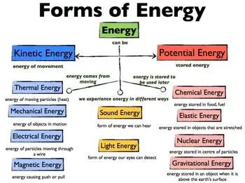
Different Types of Energy?

Energy can be classified into various types based on origin, nature, and form. Each type has unique characteristics, examples, and applications in everyday life and industry.

Mechanical Energy

Mechanical energy is the energy of motion or position. It includes:

  • Potential energy – stored energy due to position or configuration (e.g., water behind a dam).

  • Kinetic energy – energy of motion (e.g., a moving car).
    Mechanical energy is widely used in engines, turbines, and machines.


Thermal Energy

Thermal energy is related to the temperature of an object or system, arising from the kinetic motion of its atoms and molecules. It transfers between objects as heat. Everyday examples include boiling water, heating systems, and combustion engines.


Chemical Energy

Chemical energy is stored in the bonds of molecules and released during chemical reactions. Examples include gasoline fueling a car, food fueling our bodies, and batteries powering electronics. It underpins most biological and industrial processes.
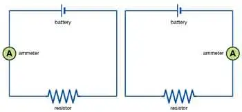
 

Electrical Energy

Electrical energy results from the movement of electrons through a conductor. It powers lighting, electronics, appliances, and the global power grid. It is easily transported and converted into other forms of energy. Since energy drives current flow, learning about Electrical Energy and how it relates to Voltage and Current makes the concept more practical.


Radiant Energy

Radiant energy is carried by electromagnetic waves, including visible light, radio waves, and microwaves. It enables vision, communication systems, and solar power technology. Sunlight is the most significant source of radiant energy on Earth.


Gravitational Potential Energy

Gravitational energy is stored by objects in a gravitational field due to their height or mass. Lifting an object, climbing a hill, or operating a hydroelectric dam all rely on gravitational potential energy.


Nuclear Energy

Nuclear energy is released during atomic reactions, such as fission (splitting nuclei) or fusion (combining nuclei). It is harnessed in nuclear power plants to generate electricity and powers stars through fusion.


Sound Energy

Sound energy comes from the vibrations of particles in a medium such as air, water, or solids. It is essential in communication, music, sonar, and countless daily experiences.


Comparison Table of Energy Forms

Form Definition Example Common Use / Efficiency
Mechanical Motion or position (kinetic + potential) Car in motion, dam reservoir Engines, machines, turbines
Thermal Motion of atoms/molecules, heat transfer Boiling water Heating, engines
Chemical Energy in molecular bonds Gasoline, food, batteries Fuels, metabolism, storage
Electrical Electron flow through conductors Light bulb, power lines Appliances, power systems
Radiant Electromagnetic waves Sunlight, radio waves Solar panels, communications
Gravitational Position in a gravitational field Falling rock, hydro dam Hydropower, lifting systems
Nuclear Atomic fission/fusion Nuclear reactor, stars Electricity generation
Sound Vibrations in the medium Music, sonar, speech Communication, entertainment


What is Energy in Everyday Life?

Energy is used in numerous everyday activities, including heating and cooling homes, cooking, transportation, communication, and entertainment. Energy use has increased dramatically with the growth of technology and the global population. However, the availability of energy sources is limited, and the demand is increasing. This has led to a search for alternative and renewable energy sources, such as solar, wind, hydropower, and geothermal energy. The physics of 3 phase electricity and 3 phase power demonstrates how energy is efficiently distributed through modern power grids.

Renewable energy sources, such as solar energy, are gaining popularity due to their clean, sustainable, and renewable nature. Solar energy is derived from the sun's radiation and can be converted into electricity through photovoltaic (PV) cells or concentrated solar power (CSP) systems. Solar energy is utilized for various purposes, including generating electricity, heating water, and drying crops. The relationship between energy, Active Power, and Reactive Power is key to understanding how electricity performs useful work.


What is Energy in Physics?

In physics, the concept of energy is closely tied to thermodynamics, which explains how heat and work are transferred within systems. The law of conservation of energy ensures that energy is never lost, only changed in form through conversion processes. Whether it is the power delivered by an engine, the work performed by a force, or the density of energy stored in fuels and batteries, different forms of energy shape how the physical world operates and how technology supports human progress.

  • Biology: Cells use chemical energy stored in ATP for growth and repair.

  • Physics: Einstein’s equation E = mc² links matter and energy, essential in cosmology and nuclear physics.

  • Engineering: Modern grids rely on energy storage (batteries, pumped hydro), demand response, and smart systems to balance supply and demand.

Energy principles are also explained through fundamental laws, such as Ohm’s Law and Ampere’s Law, which connect voltage, current, and resistance.


Future of Energy

As global demand increases, the future of energy will focus on improving storage systems and raising energy density in fuels and batteries. Advances in renewable systems must also balance the conservation of resources with reliable power delivery. New technologies are being developed to optimize energy conversion and minimize losses, ensuring sustainable solutions for future generations. The future hinges on decarbonization, the integration of renewable energy, and global policy shifts. Fossil fuel limitations and climate change demand innovation in:

  • Large-scale storage (lithium batteries, hydrogen fuel cells).

  • Grid modernization and smart energy management.

  • Sustainable policy frameworks balancing demand with environmental limits.

Energy is not only a scientific concept but also a central issue shaping economies, technology, and our planet’s survival.


How is energy measured and quantified?

Energy is typically measured in joules (J) or kilojoules (kJ). The joule is the unit of measurement for energy in the International System of Units (SI). For example, one joule is the amount of energy needed to move an object with a force of one newton (N) over a distance of one meter (m). Kilojoules (kJ) measure larger amounts of energy, such as the energy content of food or the energy output of power plants.

Energy measurements vary depending on the forms being studied. For instance, thermal systems adhere to the laws of thermodynamics, whereas electrical systems prioritize power output and efficiency. Units like joules, calories, and kilowatt-hours quantify the work done, while energy density helps compare fuels and storage methods in practical applications.

Beyond joules, energy is measured in:

  • Calories – food energy.

  • BTU (British Thermal Unit) – heating and fuel.

  • Kilowatt-hours – electricity billing.

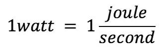
Conversions between units help bridge the gap between physics, engineering, and daily life. For example, a 100-watt light bulb consumes 100 joules every second.


Frequently Asked Questions


What is the difference between energy and power?

Energy is the capacity to do work; power is the rate of energy transfer, measured in watts (joules per second).


Can energy be created?

No. According to the law of conservation, energy cannot be created or destroyed, only transformed.


What is energy density?

Energy density refers to the amount of energy stored per unit mass or volume, which is particularly important in fuels and batteries.


How is energy related to thermodynamics?

The first law describes conservation; the second law explains inefficiencies and entropy.


Related Articles


Related News

What is an Ampere?

An ampere is the standard unit of electric current in the International System of Units (SI). It measures the flow of electric charge in a circuit, with one ampere equal to one coulomb of charge passing through a point per second.


What is an Ampere?

The ampere (A) is one of several units used to measure the electromagnetic force between straight, parallel conductors carrying electric current.

✅ Measures electric current or flow of electric charge per second

✅ Defined as one coulomb of charge per second in a conductor

✅ Essential in circuit design, safety, and load calculations


Scientific Definition and Formula

The ampere is defined by the formula:

  • V is voltage in volts

  • R is resistance in ohms

  • I is current in amperes

When you explore Ohm’s Law, you'll learn how voltage and resistance influence current using the formula I = V / R.


Safety Considerations

Electric current levels and their effects on the human body:

  • 1 mA: barely perceptible

  • 5–10 mA: painful shock

  • 50 mA: can cause breathing difficulty

  • 100 mA: potentially fatal if it passes through the chest

Even small currents, if applied in the wrong way, can be dangerous, especially in wet conditions.


Applications of Amperes

  • Power system design: selecting proper wire gauges and protective devices

  • Circuit protection: fuses and circuit breakers are rated in amperes

  • Electronics: current limits are vital in component design

  • Battery ratings: indicate how much current a battery can safely deliver

An ammeter is essential for measuring current directly in amperes within a circuit.


Although the ammeter can measure electric flow in coulombs per second, it is calibrated or marked in amperes. For most practical applications, the term amperes is used instead of coulombs per second when referring to the amount of current flow. Note the use of the prefixes micro and milli to represent very small amounts of current and kilo and mega to represent very large amounts.  The article on the ampere explains why one coulomb per second is foundational to electrical theory. Exploring power factor reveals how reactive energy and real power interact in systems with large currents.

A current of a few milliamperes will give you a startling shock. About 50 mA will jolt you severely, and 100 mA can cause death if it flows through your chest cavity.

An ordinary 100-watt light bulb draws a current of about 1 A. An electric iron draws approximately 10 A; an entire household normally uses between 10 A and 50 A, depending on the size of the house, the types of appliances it has, and also the time of day, week, or year. Learning about the watt helps readers see how power (watts) relates to current (amperes) and voltage.

The amount of current that flows in an electrical circuit depends on both the voltage and the resistance. There are some circuits in which extremely large currents, say 1000 A, flow; this might happen through a metal bar placed directly at the output of a massive electric generator. The resistance is extremely low in this case, and the gen­erator is capable of driving huge amounts of charge. In some semiconductor electronic devices, such as microcomputers, a few nanoamperes are often sufficient for many complex processes. Some electronic clocks draw so little current that their batteries last as long as they would if left on the shelf without being used at all. Reading about electricity safety shows why even small currents—measured in amperes—can pose serious hazards.

Related Articles


View more

What is Impedance? Explained

Impedance is the total opposition a cable or circuit offers to alternating current (AC). It combines resistance and reactance, measured in ohms (Ω), and determines how easily AC signals move through a circuit, affecting voltage, current, and power.


What is Impedance?

Impedance refers to the opposition that an electrical circuit presents to the flow of alternating current. It is a complex quantity that combines resistance and reactance, shaping how signals behave in AC systems.

✅ Combines resistance and reactance in AC circuits

✅ Measured in ohms and affects signal flow and power

✅ Essential in analyzing voltage, current, and circuit behavior


Understanding impedance (Z) is essential for anyone working with AC circuits. It influences how electrical energy flows, how efficiently components interact, and how systems handle varying frequencies. To understand how impedance interacts with voltage, explore our explanation of what is voltage and how it affects current flow in electrical circuits.

Electrical resistance is the opposition to direct current, while reactance opposes alternating current. Reactance arises from capacitors and inductors: capacitive reactance decreases with frequency, while inductive reactance increases. Together, these elements define the circuit’s impedance and its effect on current, voltage, and power transfer.

Impedance is crucial in AC circuit analysis because it enables engineers and technicians to calculate how voltage and current behave. This understanding facilitates efficient design, troubleshooting, and energy transfer, particularly when impedance matching is necessary for optimal performance. In AC systems, the behavior of inductors is described by inductance, which directly contributes to the reactive part of impedance.


Impedance Formula and Complex Representation

Impedance is defined mathematically by the formula:

Z = V / I

Where:

  • Z is impedance in ohms (Ω)

  • V is voltage (volts)

  • I is current (amperes)

This relationship is a natural extension of Ohm’s Law, which defines the link between voltage, current, and resistance in DC circuits. In AC analysis, impedance expands this concept by including reactance and phase angle.

In AC systems, impedance is expressed as a complex impedance:

Z = R + jX

Where:

  • R is resistance (real part)

  • X is reactance (imaginary part)

  • j is the imaginary unit

This representation accounts for both magnitude and phase angle, enabling the modelling of the interaction between voltage and current in AC circuits. Capacitors also play a key role, and understanding capacitance is essential to see how impedance decreases at higher frequencies.


Frequency, Phase Angle, and Reactance

Impedance depends on frequency. As frequency increases, reactance (especially inductive and capacitive) also changes, which shifts the phase angle between voltage and current.

  • Inductive reactance (XL = 2πfL) increases with frequency

  • Capacitive reactance (XC = 1 / 2πfC) decreases with frequency

As a result, the total impedance can change significantly depending on the signal. Engineers must consider this when analyzing harmonics or designing high-frequency systems. Learn how resistance contributes to impedance by reviewing what is electrical resistance and how it differs from reactance in AC systems.


Common Applications of Impedance

Understanding impedance is critical in many areas of electrical and electronic engineering:

  • Audio Systems: Proper impedance matching ensures maximum power transfer and sound clarity between amplifiers and speakers.

  • Radio Frequency (RF): Antenna design and transmission lines rely on precise impedance matching to minimize signal loss.

  • RLC Circuits: Impedance analysis enables tuning and resonance calculations in resistor-inductor-capacitor (RLC) networks.

  • Power Systems: Impedance affects fault current calculations, load flow, and harmonic analysis.

  • Phasor Analysis: Engineers use phasors to represent voltage and current in the frequency domain, relying on impedance to model AC behavior. For insights into the capacitive elements of impedance, see what is a capacitor and how it stores energy in electric fields.


Power System Impedance (Advanced)

At fundamental frequency, power systems are mostly inductive, and the equivalent impedance is often described as short-circuit reactance. While capacitive effects are typically minor in utility and industrial systems, they become significant in harmonic analysis. Short-circuit impedance, often derived from system studies, is a critical factor in these calculations.


Short-Circuit Reactance

If phase data is unavailable, engineers usually assume impedance is purely reactive—a reasonable approximation in many cases. However, transformer and line resistance may need to be considered for accurate harmonic modeling. The inductive reactance portion of impedance scales linearly with frequency, and engineers must carefully apply this when analyzing short-circuit conditions.


Transformer Resistance Effects

Resistance in transformers and conductors can change with frequency due to skin effect or eddy current losses. Large substation transformers, for example, may exhibit resistance that increases almost in proportion to frequency, which can help dampen resonance. In smaller transformers, winding resistance dominates and remains nearly constant until higher frequencies are reached. At utilization voltages, such as in industrial power systems, the service transformer’s impedance often accounts for more than 90% of total system impedance.

Transformer impedance in ohms can be estimated from the nameplate percentage impedance:

Z (Ω) = (Z% / 100) × (V² / kVA)

For instance, a 1,500 kVA transformer with a 6% impedance at 480 V has an equivalent impedance of approximately 9.22 Ω. This simplification is often sufficient to evaluate harmonic resonance risks and system behavior. For more on efficiency, review what the power factor is and its impact on AC systems.


Harmonic Considerations

One common mistake in harmonic analysis is neglecting to adjust reactance for frequency. The reactance at the h-th harmonic is determined from the fundamental reactance X1 by:

where h is the harmonic number and X1 is the fundamental reactance magnitude. (For capacitive branches specifically: XC,h = XC,1 / h, while inductive branches scale as XL,h = h × XL,1.)

In many power systems, resistance remains nearly unchanged up to the ninth harmonic. However, at higher frequencies, skin effect increases conductor resistance, and transformer eddy current losses further influence apparent resistance. These factors affect resonance conditions and can alter predictions of harmonic distortion.

Neglecting resistance generally yields a conservative, higher prediction of distortion. But when transformer effects dominate system behavior, resistance should be modeled more carefully. Impedance matching is especially important in such cases for ensuring stability and avoiding resonance issues in AC power systems. The impact of impedance extends to system-level issues like harmonic distortion, which can affect stability and power quality if not managed correctly.


Calculating Total Impedance

The total impedance (Z_total) of a circuit depends on how elements are connected:

Series circuits:

Z_total = √ (R_total² + (X_L – X_C)²)

Parallel circuits:

Z_total = 1 / (1/Z₁ + 1/Z₂ + …)

These calculations follow the same principles as Ohm’s Law, but are adapted for AC circuits where both resistance and reactance determine the current flow. By combining these components, engineers can predict circuit response, design filters, and ensure efficient energy transfer. Calculating impedance is a crucial part of power system analysis, where accurate models enable the prediction of current flow, voltage stability, and fault levels.


Impedance Matching and Spectroscopy

Impedance matching adjusts the source and load to the same impedance, maximizing power transfer and minimizing reflections. It is essential in audio systems, RF communications, and transmission line design.

Impedance spectroscopy extends the concept further, analyzing a material or device across a range of frequencies. This method reveals electrical properties such as conductivity, dielectric response, and electrochemical behavior, guiding the design of advanced materials and devices.


Conclusion

Impedance is a cornerstone of AC circuit analysis, uniting resistance and reactance into a single complex value that varies with frequency. From audio clarity to power system stability, impedance shapes how electricity flows and interacts in real-world systems. By mastering impedance—whether matching speaker loads, modeling harmonic resonance, or studying material properties—engineers and technicians can design more efficient, reliable, and safe electrical systems.


Related Articles


View more

What is a Potentiometer?

A potentiometer is a variable resistor that adjusts voltage in a circuit. It’s used for controlling electrical devices like volume knobs, sensors, and dimmers. Potentiometers regulate current flow by varying resistance, making them essential in analog electronic applications.


What is a Potentiometer?

A potentiometer is a type of adjustable resistor used to control voltage or current in an electrical circuit.

✅ Adjusts resistance to control voltage in circuits

✅ Commonly used in audio controls and sensors

✅ Essential for analog signal tuning and regulation

At its core, a potentiometer functions as a variable resistor. By moving the wiper (a movable terminal) across a resistive element, the device varies the output voltage. Depending on the position of the wiper, varying amounts of resistance are introduced into the circuit, thereby adjusting the current flow.

When the wiper moves along the resistive track, it adjusts the total resistance in the circuit, which controls the flow of current. To learn more, see our guide on Electrical Resistance.

A potentiometer acts as an adjustable Voltage divider, splitting the input voltage proportionally between two output terminals based on the wiper’s position.

This relationship is governed by Ohm’s Law Formula, which states that voltage equals current multiplied by resistance (V = IR).

As shown in Figure 6-8, the basic construction of a potentiometer includes:

  • A resistive track (usually carbon, cermet, or wire wound)

  • A movable wiper

  • Three terminals (two fixed, one connected to the wiper)

This setup enables the potentiometer to function as both a voltage divider and a simple variable resistor.


Fig. 6-8 Construction geometry of a potentiometer


Types of Potentiometers

Potentiometers come in several forms, each designed for specific applications:

A potentiometer is considered a variable resistor, one of several important types covered in our guide to Types of Resistors.


Rotary Potentiometer

The most common type, rotary potentiometers, adjust resistance through the rotation of a knob. These are frequently found in volume controls, light dimmers, and measuring instruments. The resistive track inside a potentiometer is made from materials that partially conduct electricity, such as carbon or cermet. For more on conductive materials, see Conductor of Electricity.


Figure 6-9 illustrates the typical circuit symbol for a rotary potentiometer.


Linear Potentiometer (Slide Potentiometer)

Instead of rotating, a linear potentiometer, often referred to as a slide potentiometer, adjusts by sliding a control lever. These are widely used in audio mixers and precision instruments where fine, linear adjustments are needed.


Audio Taper Potentiometer

In audio equipment, human hearing sensitivity is non-linear. Audio taper potentiometers adjust resistance logarithmically to provide a natural, smooth volume change that matches human perception.

Note: If you use a linear-taper potentiometer for audio volume control, the sound may seem to jump suddenly instead of increasing smoothly.


Digital Potentiometer

Digital potentiometers, also known as "digipots," are electronically controlled rather than manually adjusted. They find use in automatic tuning circuits, programmable amplifiers, and microcontroller applications.


Rheostat (Variable Resistor)

Although technically a type of potentiometer, a rheostat uses only two terminals: one fixed terminal and the wiper. It is optimized to control current rather than voltage. Rheostats are commonly used in applications like motor speed control and light dimming.


Practical Applications of Potentiometers

Potentiometers are found in a wide range of everyday and industrial applications:

  • Audio Equipment: Volume and tone controls on stereos and guitars

  • Automobiles: Throttle position sensors, dashboard dimmers

  • Industrial Controls: Machinery speed adjustments

  • Consumer Electronics: Game controller joysticks

  • Laboratory Equipment: Calibration and fine adjustments

Potentiometers are versatile components used in both AC and DC electrical systems, from audio controls to automotive sensors.

Their ability to fine-tune voltage and resistance makes them essential in both analog and digital systems.


How to Test a Potentiometer

Testing a potentiometer is straightforward:

  1. Disconnect power to the circuit.

  2. Use a multimeter set to measure resistance (ohms).

  3. Connect the multimeter probes to the outer two terminals to measure total resistance.

  4. Measure between the wiper and one outer terminal; adjust the control and observe the changing resistance.

Consistent, smooth changes confirm proper operation. Jumps or dead spots may indicate a worn or faulty potentiometer.

A potentiometer is a simple but versatile component that provides adjustable control over voltage or resistance in a circuit. Whether used in audio systems, automotive sensors, or industrial machinery, its importance in electronic design and control systems is undeniable.

Understanding the various types and practical applications of potentiometers can help in selecting the appropriate device for a specific task.

For readers seeking a broader understanding of basic electrical principles, visit our overview of Electricity Fundamentals.


Frequently Asked Questions


What is the difference between a potentiometer and a rheostat?

A potentiometer typically acts as a voltage divider with three terminals, while a rheostat uses only two terminals to control current.


Where are potentiometers commonly used?

Potentiometers are used in volume controls, sensors, gaming controllers, industrial equipment, and calibration tools.


How does a potentiometer adjust voltage?

By moving the wiper across the resistive track, a potentiometer divides the input voltage proportionally between the two output terminals, adjusting the output voltage.


Related Articles


View more

What is a Busbar?

A busbar is a metallic strip or bar used in electrical systems to conduct electricity within switchgear, distribution panels, and substations. It distributes power efficiently and reduces resistance, enhancing safety and electrical performance.


What is a Busbar?

A busbar is a crucial electrical component used to conduct, distribute, and manage power in electrical systems. Found in commercial, industrial, and utility applications, it helps centralize connections and minimize wiring complexity.

✅ Provides efficient power distribution in electrical panels and substations

✅ Reduces resistance and improves system reliability

✅ Supports compact, organized electrical design for switchgear and distribution boards

A Busbar is an important component of electrical distribution systems, providing a central location for power to be distributed to multiple devices. It is an electrical conductor responsible for collecting electrical power from incoming feeders and distributing it to outgoing feeders. They are made of metal bars or metallic strips and have a large surface area to handle high currents.

How Does it Work?

It is a strip or bar made of copper, aluminum, or another conductive metal used to distribute electrical power in electrical systems. They have a large surface area to handle high currents, which reduces the current density and minimizes losses. They can be insulated or non-insulated, and they can be supported on insulators or wrapped in insulation. They are protected from accidental contact by either a metal earthed enclosure or elevation out of normal reach.

They collect electrical power from incoming feeders and distribute it to outgoing feeders. The bus bar system provides a common electrical junction for various types of electrical equipment, designed to handle high currents with minimal losses. They are often used in industrial applications, where they are installed in electrical panels or switchgear panels.


Different Types of Busbars

Different types of busbars are available on the market, including those made of copper or aluminum, as well as insulated or non-insulated, and segmented or solid busbars. Copper or brass busbars are used in low-voltage applications, while aluminum busbars are used in high-voltage applications. Insulated busbars are used in situations where accidental contact can occur, and segmented busbars are used to connect different types of equipment.

Busbars can also be classified based on their cross-section. A rectangular is the most common type and is often used in low-voltage applications. On the other hand, a tubular busbar is a hollow cylinder used in high-voltage applications. Finally, a circular one has a circular cross-section and is used in high-current applications.


Busbar Types and Characteristics

Attribute Copper Busbar Aluminum Busbar Laminated Busbar
Conductivity Excellent (≈100% IACS) Good (≈61% IACS) Varies (depends on internal conductor materials)
Weight Heavy Lightweight Moderate
Cost Higher Lower Higher (due to fabrication complexity)
Heat Dissipation Excellent Good Excellent (designed to reduce hot spots)
Applications Switchgear, substations, panels Bus ducts, high-rise buildings Compact power modules, UPS, power electronics
Mechanical Strength High Moderate Moderate to High
Corrosion Resistance High (especially tinned copper) Requires anodizing/coating Depends on encapsulation
Ease of Fabrication Good Excellent Complex


The Purpose of a Busbar in an Electrical System

The primary purpose of an electrical system is to distribute electrical power to different parts of the system. The busbar system collects electrical power from incoming feeders and distributes it to outgoing feeders. Busbars also provide a common electrical junction for different types of electrical equipment.


Busbar and Circuit Breakers

They are often used in conjunction with circuit breakers. Circuit breakers protect electrical circuits from damage caused by overload or short circuits. Additionally, they can be used to isolate the electrical supply in the event of a fault or overload. Circuit breakers are often installed in electrical or switchgear panels, which can be easily accessed and maintained.


Busbars and Electrical Distribution Equipment

They are an essential component of electrical distribution equipment, including electrical panels, switchgear panels, and distribution boards. Electrical panels distribute power to various parts of a building, while switchgear panels control the flow of electrical power in industrial applications. Distribution boards divide the electrical supply into separate circuits at a single location.


Busbar Installation

Installing a busbar involves several basic steps. First, the busbar system's design must be created, considering both the electrical load and the required current-carrying capacity. Then, it is installed in the electrical panel or switchgear panel. Finally, it is connected to the electrical equipment using either bolts, clamps, or welding.


Maintenance

Maintaining a busbar system involves regular inspections and cleaning. The system should be inspected for any damage or corrosion, and the connections should be tightened if they become loose. Regular cleaning of the system is also essential to prevent the buildup of dust or dirt, which can lead to a short circuit.


Safety Precautions

Working with busbars involves high voltage and current, so taking proper safety precautions is essential. The system must be isolated from the electrical system before any maintenance is performed. Personal protective equipment, such as gloves and safety glasses, should be worn while working with busbars. Working on a live system should only be done by trained personnel after ensuring that all necessary safety precautions are in place.


Accidents involving Busbars

Accidents can occur when working with busbars, and they can be dangerous if proper safety precautions are not taken. One common accident that can occur involves accidental contact with a live one. This can cause electrical shock, burns, and even death. Another accident involves short circuits, which can lead to equipment damage, fire, or explosions. These accidents can be prevented by following proper safety procedures and wearing personal protective equipment.

Arc flash accidents, including busbars, are a potential hazard when working with electrical equipment. An arc flash is an electrical explosion that can occur when a fault occurs in an electrical circuit, resulting in a short circuit or electrical discharge. Arc flash accidents can cause severe burns, hearing loss, and even death.

They can be a source of arc flash accidents if proper safety precautions are not taken. For example, if a live busbar comes into contact with an object, it can cause an arc flash. Proper insulation and guarding are necessary to prevent arc flash accidents involving busbars. They should also be installed in a way that minimizes the possibility of accidental contact.

Additionally, they should be designed to handle the expected current load, as overloading can lead to a fault and an arc flash. It is also essential to follow proper maintenance procedures, including regular system inspections and cleaning, to prevent damage or corrosion that can cause faults and arc flashes.

Overall, busbars are related to arc flash accidents as they can be a source of electrical faults that can lead to an arc flash. Therefore, following proper safety procedures, including proper insulation, guarding, and system maintenance, is crucial to prevent arc flash accidents.


Related Articles


View more

How Electricity Works

Electricity works by moving electrons through a conductor, creating an electric current. Power stations generate electricity, which travels through wires to homes and businesses. This flow powers devices, lights, and machines, making modern life possible through electric energy and circuits.


Explain How Electricity Works

✅ Electrons move through conductors to create electric current

✅ Power plants convert energy into usable electricity

✅ Electrical systems distribute power to homes, industries, and devices


What Is Electricity and Where Does It Come From?

Electricity energy is as common to us as running water in many areas, especially in industrialized countries. Despite this, there is a great deal of ignorance about this mysterious force and its origin. 

  • The concept of voltage is central to how electricity flows, as it represents the electrical pressure that pushes electrons through a circuit.

  • Understanding alternating current is essential, as it's the form of electricity most commonly delivered to homes and businesses.


Atomic Structure and the Nature of Electric Charge

If you can picture an atom as a sphere, imagine in the nucleus, in the centre, that contains at least one proton and at least one neutron. The proton is positively charged. In orbit around the nucleus is at least one electron, which is negatively charged. The reason they have these opposite charges takes us deep into the realm of quantum physics. We know that the neutron is made up of quarks and the electron is an elementary particle (it is not made up of anything and is a particle in its own right), but the reason why they have opposite charges is a matter beyond my meagre capabilities and, in any case, this area is at the fringes of human knowledge.


Electron Movement and Free Charge in Conductive Materials

Atoms may contain several protons and electrons. This variation is what distinguishes one element from another. Although described as sub-atomic particles, electrons have the properties of both particles and waves when it comes to fields of magnetism in electric circuits. In theory, at least, they could be both at the same time. If you want to know what materials conduct electricity well, see our overview of conductors, which explains how they allow electrons to move freely.

If an atom has no electric charge, i.e. it is neutral, then it contains the same number of protons as electrons. In some materials, most notably metals, the electrons' orbits around the nucleus are quite loose, allowing them to spin away from the atom. When this happens, the atom becomes positively charged because protons are in the majority within the atom. A free electron can join another atom. When this occurs, then the new host atom becomes negatively charged because the electrons are in the majority (assuming the atom was neutral in the first place). Devices like ammeters and multimeters are essential for measuring electrical current and diagnosing circuit performance.


Potential Difference and the Creation of Electric Current

There are many views about the subject. If you ask science experts on YouTube to show how static electricity works, they will report that opposites attract. The greater the difference between the number of electrons and protons, the greater the attraction will be. This is called a potential difference. If we can therefore manage to produce a negative charge at one end of a copper wire and a positive charge at the other end, free electrons would move towards the positive end. As electrons leave those atoms nearest the positive end, they leave behind positively charged atoms. Electrons from neighbouring atoms will be attracted towards these positive atoms, thus creating yet more positive atoms in their wake. This continuing transfer of electrons is called current. The greater the potential difference, or voltage, measured in its unit, the greater the force of the flow of electrons, or current.


Understanding Direct and Alternating Current (DC vs AC)

Electric power can be supplied as direct current (e.g. from car batteries for lighting) or as alternating current (e.g. household mains). To explore the differences between current types, read our guide on the difference between AC and DC, which explains why each type is used in different applications.


How Transformers Adjust Voltage for Power Distribution

Often, an electrical product requires a different voltage from the one supplied by the mains electric power. In these cases, a transformer rating is required. The use of transformers is very common along power lines and in electrical devices. In addition to the step-up transformers that increase voltage, transformers can also reduce voltage. These step-down transformers can be found at utility substations where the very high voltages required to push electrons through long transmission wires are reduced for local consumption.


Related Articles


View more

What Is Alternating Current

Alternating current (AC) is a type of electrical flow where the direction of current reverses periodically. Used in most homes and industries, AC is efficient for long-distance transmission and powers devices like motors, lights, and appliances through oscillating voltage.


What is Alternating Current?

Alternating current is a fundamental aspect of electrical systems that have shaped our world in countless ways. Its ability to be easily generated, converted to different voltages, and transmitted over long distances has made it the preferred choice for power transmission and distribution. Additionally, the many advantages of AC, such as compatibility with various devices and safety features, have made it indispensable in our daily lives.

✅ Powers homes, businesses, and industrial equipment through reliable energy transmission.

✅ Changes direction periodically, unlike DC, which flows one way.

✅ Enables long-distance energy delivery with reduced power loss.


To answer the question: What is alternating current? We need to first understand the role of a conductor, which is essential in AC systems, as conductors carry the oscillating electrical energy throughout circuits.


Aspect Description Related Concept
Definition Electric current that periodically reverses direction, forming a sine wave. What is Alternating Current
AC vs. DC AC changes direction; DC flows in one direction only. Difference Between AC and DC
Waveform Typically sinusoidal, but can also be square or triangular. Impedance
Frequency Number of cycles per second (50 Hz or 60 Hz depending on the region). Unit of Electrical Resistance
Voltage Transformation Easily adjusted using transformers for long-distance transmission. Transformer Grounding
Measurement Tools Multimeters and voltmeters measure AC voltage and current. What is a Multimeter, What is a Voltmeter
Key Components Conductors, capacitors, resistors, and inductors are essential to AC systems. What is a Capacitor, What is a Conductor
Generation Principle Based on electromagnetic induction through rotating magnetic fields. Electromagnetic Induction
Common Applications Powering homes, industrial machines, and electrical grids. Electricity Grid
Inventor Nikola Tesla pioneered practical AC power systems and the induction motor. History of Electricity


Understanding AC and DC

In the world of electricity, there are two primary forms of electric current: alternating current (AC) and direct current (DC). Understanding the distinctions between these two types of currents and their applications in daily life is essential to appreciate the advances in electrical engineering and the technology that surrounds us. A multimeter is commonly used to measure AC voltage and current in residential and industrial electrical systems.


AC vs. DC: Basic Differences

AC and DC are two distinct methods by which electric charge is transferred through a circuit. AC involves the flow of charge that periodically reverses direction, creating a waveform typically resembling a sine wave. On the other hand, DC refers to the flow of charge in a single, constant direction. The differences in their nature, functionality, and applications create a contrasting landscape in the electrical power sector. Devices like the voltmeter are specifically designed to measure AC or DC voltage, helping technicians verify circuit functionality and safety.


Why AC Is Preferred for Power Transmission

One key reason why AC is preferred over DC is its ability to easily convert to and from high voltages, making electric power transmission across long distances more efficient. Additionally, transformers can increase or decrease AC voltage, resulting in minimal power loss during long-distance transmission. In contrast, DC power cannot be altered as conveniently, making it less suitable for power transmission over extended distances.


How Alternating Current Works

The working principle of AC is centred around the changing magnetic field created by the flow of electric current. As the current changes direction, the magnetic field also alternates, inducing a voltage in the nearby conductors. This property of AC is fundamental to the operation of AC generators and transformers.

  • AC operation is based on electromagnetic induction

  • Rreversal creates alternating magnetic fields

  • Voltage is induced in nearby conductors


The Role of Nikola Tesla in AC Development

The invention of AC can be attributed to multiple individuals, but the Serbian-American inventor, Nikola Tesla, is often credited with pioneering AC systems. Tesla's work on AC power transmission and his development of the induction motor helped establish AC as the dominant form of electricity.


Frequency: 50 Hz vs. 60 Hz

In frequency, the terms 50-cycle and 60-cycle AC refer to the number of times the current changes direction in one second. The frequency of AC power varies globally, with 50 Hz being the standard in many parts of Europe, Asia, and Africa, while 60 Hz is the norm in North America.

  • 50 Hz is standard in Europe, Asia, and Africa

  • 60 Hz is common in North America

  • Frequency affects compatibility and performance of electrical devices

This difference in frequency can affect the operation of certain appliances and devices, making it essential to use the appropriate frequency for the intended purpose.


Advantages of Alternating Current

The advantages of AC over DC extend beyond efficient power transmission. AC is easier to generate and is widely used for electric power generation, making it more accessible and cost-effective. Moreover, AC systems are safer as they can be easily switched off when required, reducing the risk of electrical accidents. AC is versatile and can power various devices, from small household appliances to large industrial machines.

Key benefits of AC:

  • Easily transformed to higher or lower voltages

  • Safer switching and control in circuits

  • Powers a wide range of residential and industrial devices


How AC Is Generated and Transmitted

The generation and transmission of AC are crucial components of the electrical power infrastructure. AC is generated through various means, such as hydroelectric, thermal, and nuclear power plants, which use generators to convert mechanical energy into electrical energy.

Transmission components:

  • Transformers: Adjust voltage levels

  • Transmission towers: Carry high-voltage lines

  • Substations: Regulate voltage for safe end-use

Once generated, AC is transmitted through power lines that consist of transformers, transmission towers, and substations, which adjust the voltage levels for efficient distribution and usage.


The Role of AC in Daily Life

AC plays a vital role in our daily lives, as it powers most of the appliances and devices we rely on, including lights, computers, and household appliances. In addition, its compatibility with transformers, ease of generation, and ability to transmit power over long distances make it a cornerstone of modern electrical systems.

Frequency has a notable impact on AC usage. In addition to determining the compatibility of devices with a region's power supply, the frequency of AC power affects the speed and performance of electrical motors. A change in frequency may result in the motor operating at a different speed or, in some cases, causing it to malfunction.

Transformers are essential devices in AC systems, as they adjust voltage levels to meet the requirements of various applications. They function by utilizing the principle of electromagnetic induction, where a changing magnetic field in the primary coil induces a voltage in the secondary coil. By adjusting the number of turns in the coils, transformers can efficiently increase or decrease the voltage of AC power, depending on the specific application's needs.

The differences between AC and DC are crucial in understanding the diverse landscape of electrical power. The invention of AC by Nikola Tesla and other inventors has revolutionized the way electricity is generated, transmitted, and utilized. With an appreciation for the characteristics and applications of AC, we can gain a deeper understanding of the technology and infrastructure that powers our world.


How Does Alternating Current Work?

AC works by periodically reversing the direction of the electric charge flow within a circuit. In contrast to DC, which flows in a constant direction, AC oscillates back and forth. This oscillation is typically represented as a waveform, often in the shape of a sine wave. Let's dive deeper into how AC works.

AC is characterized by a waveform that typically takes the shape of a sine wave, allowing for smooth and continuous changes in voltage over time. This makes it ideal for long-distance transmission across the power grid, where electricity generated by a generator must travel efficiently to homes and businesses. The frequency of this current—measured in cycles per second or hertz (Hz)—determines how rapidly the voltage changes direction, impacting device performance and grid efficiency. As current flows through a conductor, it can be stepped up or down using a transformer, enabling voltage levels to be optimized for safe and effective delivery.

Generation: AC is generated using a rotating magnetic field to induce an electric current in a conductor. This is done using devices such as generators and alternators, which convert mechanical energy into electrical energy. In these devices, a coil of wire rotates within a magnetic field, or a magnet rotates around a stationary coil. This rotation causes the magnetic field to interact with the conductor, inducing a voltage and, consequently, an electric current that changes direction periodically.

Waveform: The alternating nature of AC is depicted by a waveform, which shows the voltage or current as a function of time. The most common waveform for AC is the sine wave, which can also take other forms, such as square or triangular waves. The waveform's shape determines the characteristics of the AC and how it interacts with various electrical components.

Frequency: One important parameter of AC is its frequency, which indicates the number of complete cycles the current undergoes per second. It is measured in hertz (Hz). Common frequencies include 50 Hz and 60 Hz, but other frequencies can also be used depending on the application. The frequency of the AC power supply affects the performance and compatibility of devices and equipment connected to it.

Voltage and current relationship: In an AC circuit, the voltage and current can be in phase (i.e., they reach their peak values simultaneously) or out of phase (i.e., they reach their peak values at different times). The phase relationship between voltage and current in an AC circuit can significantly impact power delivery and system efficiency. A voltage sag can disrupt sensitive equipment, making voltage regulation a key part of power quality analysis.

Transformers: A key advantage of AC is that its voltage can be easily changed using transformers. Transformers operate on the principle of electromagnetic induction, where a changing magnetic field in the primary coil induces a voltage in the secondary coil. By adjusting the number of turns in the coils, the transformer can step up or down the AC voltage as needed. This ability to adjust voltage levels makes AC an efficient choice for long-distance power transmission.


Frequently Asked Questions


What is the formula to calculate alternating current?

To calculate the value of AC at any given time, you need to know the current's amplitude (maximum value) and the angular frequency. The general formula for calculating instantaneous current in an AC circuit is:

i(t) = I_max * sin(ωt + φ)

Where:

  • i(t) is the instantaneous current at time t

  • I_max is the amplitude or peak current

  • ω (omega) is the angular frequency, calculated as 2πf (where f is the frequency in hertz)

  • t is the time at which you want to calculate the current

  • φ (phi) is the phase angle, which accounts for any phase shift between the voltage and the current waveforms

Remember that this formula assumes a sinusoidal waveform, the most common form of AC. If the waveform is not sinusoidal, the formula will be different and depend on the specific shape of the waveform.

Another important value for AC circuits is the root-mean-square (RMS) current, which measures the effective value of the current. The RMS current is useful for calculating power in AC circuits and can be compared to the steady current value in DC circuits. The formula to calculate RMS current from the peak current is as follows:

I_RMS = I_max / √2

Where:

  • I_RMS is the root-mean-square current

  • I_max is the amplitude or peak current

  • √2 is the square root of 2, approximately 1.414

  • Using these formulas, you can calculate the instantaneous current value for an alternating current waveform and determine the effective or RMS current value.

To understand how voltage affects electrical circuits, it's essential to examine how voltage drop can lead to energy loss, particularly over long distances.


Related Articles


View more

Sign Up for Electricity Forum’s Newsletter

Stay informed with our FREE Newsletter — get the latest news, breakthrough technologies, and expert insights, delivered straight to your inbox.

Electricity Today T&D Magazine Subscribe for FREE

Stay informed with the latest T&D policies and technologies.
  • Timely insights from industry experts
  • Practical solutions T&D engineers
  • Free access to every issue

Live Online & In-person Group Training

Advantages To Instructor-Led Training – Instructor-Led Course, Customized Training, Multiple Locations, Economical, CEU Credits, Course Discounts.

Request For Quotation

Whether you would prefer Live Online or In-Person instruction, our electrical training courses can be tailored to meet your company's specific requirements and delivered to your employees in one location or at various locations.