Neutral Grounding Resistor
By William Conklin, Associate Editor
By William Conklin, Associate Editor
Our customized live online or in‑person group training can be delivered to your staff at your location.
A neutral grounding resistor (NGR) is a resistor installed between the neutral point of a power system and ground to limit ground-fault current during a line-to-ground fault.
By inserting resistance into the neutral circuit, the device limits the magnitude of fault current, allowing protective relays to detect the fault while preventing destructive fault energy in generators, transformers, and switchgear.
In resistance-grounded systems, ground-fault current is primarily determined by the relationship between system voltage and the resistance placed in the neutral path. According to Ohm’s law, the current flowing during a ground fault is approximately equal to the system voltage divided by the grounding resistance. Selecting the correct resistance value allows engineers to limit fault current to a controlled level that protection systems can detect without exposing equipment to excessive thermal or mechanical stress.
A common misunderstanding is that grounding resistors prevent faults from occurring. They do not. A neutral grounding resistor allows ground faults to occur but limits their magnitude so the power system can continue operating safely while protective relays identify and isolate the fault.
In medium-voltage industrial and utility networks, this controlled fault behavior reduces equipment damage, limits arc-flash energy, and prevents transient overvoltages.
A neutral grounding resistor shapes ground fault behavior as part of the broader strategy that establishes electrical grounding reference and safety as explained in our formal definition of electrical earthing.
In medium-voltage industrial and utility systems, that control is often the difference between a manageable fault event and a destructive one. A neutral grounding resistor only performs as intended when integrated into grounding system architecture that organizes reference and fault control.
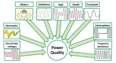
Think you know Power Quality? Take our quick, interactive quiz and test your knowledge in minutes.
Unlike solidly grounded systems, where fault currents rise rapidly and violently, resistance-grounded systems use the resistor to shape the fault into something the system can tolerate. The goal is not to eliminate fault current, but to make it predictable, detectable, and survivable.
Electrical systems do not fail politely. When insulation breaks down, current follows the laws of physics, not intentions. Without resistance in the neutral path, a ground fault can produce currents large enough to deform conductors, damage transformer windings, and create arc flash energy levels that exceed the capabilities of protective devices.
The resistor introduces a deliberate bottleneck. It limits the fault current to a level chosen by the designer, rather than leaving it to chance. That single design choice reshapes the entire fault profile of the system, a concept explained more broadly in understanding electrical earthing.
In practice, this means:
• Lower thermal stress on equipment
• Reduced arc flash energy at the fault point
• Improved selectivity for protective relays
• Greater system stability during abnormal events
This is why a neutral grounding resistor appears so frequently in mining, petrochemical plants, pulp and paper mills, large manufacturing facilities, and medium-voltage utility networks.
In resistance-grounded networks, the neutral grounding resistor serves as the primary control point for fault current behaviour. By shaping how current returns through the system neutral during a line-to-ground event, the resistor allows protection relays to distinguish between transient disturbances and sustained faults. In high-resistance grounding (HRG) systems, this often supports continued operation with fault indication, while low-resistance grounding (LRG) favors rapid isolation once detection thresholds are reached. The difference is not philosophical; it is operational, affecting relay coordination, maintenance strategy, and risk tolerance across the entire network.
From an engineering standpoint, the selection of neutral grounding resistors is closely tied to transformer neutral earthing practice, relay sensitivity, and applicable IEEE and NEC guidance on fault detection and system stability. Ground fault detection schemes rely on predictable current magnitudes, which is exactly what resistance earthing provides when properly designed. Without that predictability, even advanced protective devices lose their value in coordination, and fault localization becomes uncertain rather than diagnostic.
Two broad philosophies dominate the neutral grounding resistor.
HRG keeps fault current extremely low, often below 25 amps. In these systems, a single ground fault does not require immediate shutdown. Operators can locate and correct the problem while production continues, provided the system remains stable.
LRG allows higher fault currents, typically in the hundreds of amps. These systems are designed for fast fault clearing, where protective relays trip breakers quickly to isolate the faulted section. This approach is common in larger networks where equipment protection and coordination take priority.
In transformer-neutral earthing applications, the resistor establishes a predictable fault-current reference that protection relays use for selective coordination and ground-fault detection. HRG systems rely on this controlled current to support alarm-only fault-response strategies, whereas LRG favors rapid protective isolation.
Installation and performance expectations are governed by electrical grounding code requirements that specify grounding behavior and fault-current criteria.
Selecting a neutral grounding resistor begins with determining the ground-fault current the system should allow. In resistance-grounded networks, fault current is controlled by the relationship between system voltage and earthing resistance. In simplified form:
Ground fault current = Line-to-neutral voltage ÷ grounding resistance
Download our FREE Electrical Training Catalog and explore a full range of expert-led electrical training courses.

By choosing a specific resistance value, engineers set the maximum current that can flow during a line-to-ground fault. This allows the earthing system to limit the destructive fault energy while still providing sufficient current for protection relays to detect and isolate the fault.
In HRG systems, resistor sizing must also account for the system’s total capacitive charging current. Every cable, transformer winding, and piece of connected equipment contributes capacitance to ground. During a ground fault, that capacitance allows current to flow even without a resistor.
For reliable fault detection, the neutral grounding resistor must allow a ground-fault current that exceeds the system’s total charging current. If the resistor current is lower than the network’s capacitive charging current, protective relays may not distinguish a sustained fault from normal system capacitance, making fault detection unreliable.
On paper, the resistor is defined by Ohm’s law. In the field, it is defined by consequences.
Designers look at:
• Line-to-neutral system voltage
• Desired ground fault current limit
• Relay sensitivity and coordination margins
• Thermal withstand time
• Physical enclosure environment
• Monitoring and alarm requirements
Fault current behavior is influenced by the path defined by how the conductor that connects the grounding electrode conductor to the system reference.
The resistor must survive the worst fault the system can deliver, not just the one expected on a good day. IEEE and NEC guidance both emphasize fault current limitation as a core requirement for system stability in resistance-grounded networks.
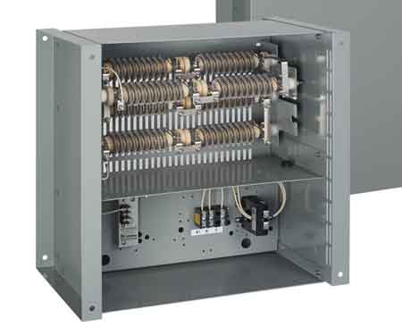
Neutral grounding resistors are built for punishment. Edge-wound elements, stainless or nickel-chromium alloys, and high-temperature insulation are not marketing features. They are survival requirements.
During a fault, the resistor converts electrical energy directly into heat. In poorly designed units, that heat becomes a mechanical failure. In properly designed units, it becomes a controlled, predictable rise that the enclosure and elements can absorb without permanent damage.
In mining installations, vibration and dust demand robust enclosures. In outdoor substations, weather resistance and thermal ventilation dominate design decisions. In indoor industrial plants, compact layouts and easy access for monitoring become more important.
The resistor is simple in principle, but unforgiving in execution.
A neutral grounding resistor that silently fails removes the entire system's protection philosophy.
Modern installations include:
• Continuity monitoring to detect open elements
• Temperature sensing to detect overheating
• Ground fault detection relays for fault localization
• Alarm outputs tied into plant control systems
Without monitoring, a system may appear grounded while operating effectively ungrounded, creating dangerous transient overvoltages and unpredictable fault behaviour, especially in transformer-fed networks, as discussed further in transformer earthing. Neutral grounding resistors are commonly applied in systems that rely on how transformer grounding neutrals are grounded in different system configurations.
In mining, regulations often require resistance earthing to control fault energy in confined spaces.
In utility distribution, they protect transformers and feeder equipment from destructive ground faults.
In renewable energy plants, they stabilize transformer earthing as inverter-based sources interact with the grid.
In large industrial facilities, they support selective coordination strategies that isolate faults without collapsing entire production networks.
Stable reference conditions depend on how grounding and bonding maintain continuity between conductive parts.
A neutral grounding resistor is not an earthing system on its own. It is one engineered component within a broader earthing strategy. Its effectiveness depends on how the neutral, conductors, electrodes, and protective devices work together.
In utility installations, resistor performance is influenced by electrode design principles that affect how electrodes support substation grounding reference.
Periodic inspection is not about compliance paperwork. It is about verifying that the resistor still behaves as the system design assumes.
Loose connections, corrosion, insulation breakdown, and blocked ventilation can all quietly degrade performance. A NGR that cannot dissipate heat or maintain continuity no longer effectively limits fault current.
When it fails, it fails invisibly.
A neutral grounding resistor does not prevent faults, but it determines whether a fault becomes a controlled electrical event or an uncontrolled system failure.
Explore 50+ live, expert-led electrical training courses –