What is Reactive Power Explained
Grounding and Bonding and The NEC - Section 250
Our customized live online or in‑person group training can be delivered to your staff at your location.
- Live Online
- 12 hours Instructor-led
- Group Training Available
Download Our OSHA 4474 Fact Sheet – Establishing Boundaries Around Arc Flash Hazards
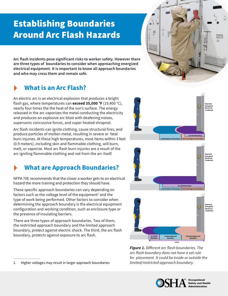
- Understand the difference between arc flash and electric shock boundaries
- Learn who may cross each boundary and under what conditions
- Apply voltage-based rules for safer approach distances
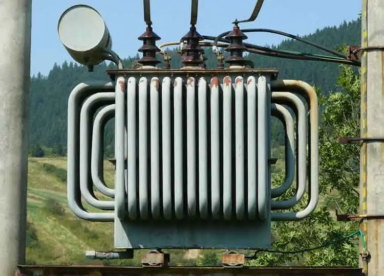
Reactive power is the energy that flows back and forth between the source and the load in AC systems. It doesn’t perform useful work but is essential for maintaining voltage regulation, grid stability, and efficient current flow. It supports inductive loads like motors and transformers in electrical distribution networks.
What is Reactive Power?
Reactive power is a type of electrical energy that does no real work and is generally associated with reactive elements (inductors and capacitors). It:
✅ Maintains voltage levels in AC electrical systems
✅ Generates magnetic fields in motors and transformers
✅ Measured in volt-amperes reactive (VAR), not watts
Power Quality Analysis Training
Request a Free Power Quality Training Quotation
For example, let's examine a basic reactive power formula involving motor load. The inductance of a load such as a motor causes the load current to lag behind the voltage. Energy appearing across the inductance, cycles back and forth between the inductive load and the energy source, producing no net work. For this reason, it is referred to as imaginary or reactive power, as no energy is dissipated or expended. It is expressed in units of volt-ampere-reactive or VAR. In the sinusoidal case, the reactive power is defined as:
…which is the portion of energy in quadrature with the active (real) power (P) and demonstrates the relationship between P, Q, and S (apparent power) in sinusoidal conditions. Reactive power is essential in maintaining system voltage, which directly relates to what is voltage and the overall efficiency of AC electrical distribution.
Reactive Power and Harmonics in Electrical Grids
There is some disagreement among harmonics analysts on how to define Q in the presence of harmonic distortion. If it were not for the fact that many utilities, which produce electromagnetic fields in transmission lines, measure Q and compute demand billing from the PF computed by Q, it might be a moot point.
FREE EF Electrical Training Catalog
Download our FREE Electrical Training Catalog and explore a full range of expert-led electrical training courses.

- Live online and in-person courses available
- Real-time instruction with Q&A from industry experts
- Flexible scheduling for your convenience
It is more important to determine P and S; P defines the amount of P being consumed, while S defines the capacity of the system required to deliver P. Q is not particularly useful by itself. However, Q1, the traditional reactive power component at fundamental frequency, may be used to size shunt capacitors for PF correction. Unlike reactive power, which does not perform real work, P represents the actual energy consumed by resistive components to perform useful tasks in electrical systems.
Relationship Between P, Q, and S in AC Systems
The reactive power, when distortion is present, has another interesting peculiarity. In fact, it may not be entirely accurate to refer to it as reactive power. The concept of VAR flow in the electrical grid is deeply ingrained in the minds of most electrical engineers. What many do not realize is that this concept is valid only in the sinusoidal steady state.
When distortion is present (as in the case of induction motors), the component of S that remains after P is taken out is not conserved—that is, it does not sum to zero at a node. Energy quantities are presumed to flow around the system in a conservative manner. It supports inductive load behavior by generating magnetic fields, a concept closely tied to what is inductance and capacitive load characteristics in electrical systems.
Distortion Power and Non-Conserved Components
This does not imply that P is not conserved or that current is not conserved, because the conservation of energy and Kirchhoff's current laws are still applicable for any waveform. The reactive components actually sum in quadrature (i.e., the square root of the sum of the squares).
Some analysts propose that Q be used to denote the reactive components that are conserved and introduce a new quantity, D, for distortion power (distortion volt-amperes). This interaction between P, reactive energy, and distortion components is key to understanding power factor correction. The interaction between real and reactive power is best understood through the lens of power factor, which measures how effectively electrical energy is converted into useful work.
It has units of volt-amperes, but it may not be strictly appropriate to refer to this quantity as electrical energy, because it does not flow through the system as energy is assumed to do. In this concept, Q consists of the sum of the traditional reactive power values at each frequency. D represents all cross-products of voltage and current at different frequencies, which yield no average power. P, Q, D, and S are related as follows:
Visualizing Reactive Power Components
Some prefer to use a three-dimensional vector chart to illustrate the relationships between reactive power components. P and Q contribute the traditional sinusoidal components to S, while R represents the additional contribution to S by the harmonics.
There are many factors to consider when determining and measuring reactive power in an AC circuit in any industrial plant, including:
-
P
-
Voltage level and voltage regulation
-
Purely resistive true power
-
Active, reactive, and S
-
Active and reactive powers under different loads
-
How to absorb reactive power in capacitive or inductive loads
What is reactive power? To better understand current flow disruptions in AC systems, compare real vs reactive power and how each influences overall electrical safety.
Test Your Knowledge About Power Quality!
Think you know Power Quality? Take our quick, interactive quiz and test your knowledge in minutes.
- Instantly see your results and score
- Identify strengths and areas for improvement
- Challenge yourself on real-world electrical topics


