Latest Building Automation Articles

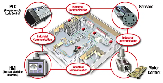
Hierarchical Levels in Industrial Networks

Hierarchical Levels Industrial Networks align device, control, and enterprise layers across PLCs, SCADA, MES, and ERP, using fieldbus, Ethernet/IP, and Profinet to ensure deterministic control, real-time data, cybersecurity, and scalable OT-IT integration.


What Are Hierarchical Levels Industrial Networks?

Layered OT networks linking devices, control, and enterprise systems for real-time, deterministic, secure automation.

✅ Defines device, control, and enterprise layers in OT/ICS

✅ Maps PLCs, HMIs, drives, and sensors to appropriate network tiers

✅ Ensures determinism, redundancy, and EMC-compliant cabling practices


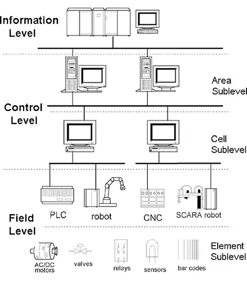
The industrial automation systems can be very complex, and it is usually structured into several hierarchical levels. Each of the hierarchical level has an appropriate communication level, which places different requirements on the communication network. Figure 1.1 shows an example of the hierarchy of an industrial automation system. For a broader overview of protocols and trends, industrial automation communication resources explain how hierarchy influences network design across levels.

Industrial networks may be classified in several different categories based on functionality - field-level networks (sensor, actuator or device buses), control-level networks (control buses) and information-level networks. Organizations adopt these layers to gain measurable efficiencies, and the benefits of industry networks include improved interoperability, uptime, and lifecycle support.

We primarily use sensor and actuator buses to connect simple, discrete devices with limited intelligence, such as a photo-eye, limit switch, or solenoid valve, to controllers and computers. Sensor buses such as ASI and CAN are designed so information flow is reduced to a few bits and the cost per node is a critical factor. Selecting cabling, interfaces, and gateways depends on understanding industrial network components that shape reliability, diagnostics, and scalability.

Field level

The lowest level of the automation hierarchy is the field level, which includes the field devices such as actuators and sensors. The elementary field devices are sometimes classified as the element sublevel. The task of the devices in the field level is to transfer data between the manufactured product and the technical process. The data may be both binary and analogue. Measured values may be available for a short period of time or over a long period of time.

For the field level communication, parallel, multiwire cables, and serial interfaces such as the 20mA current loop has been widely used from the 

past. The serial communication standards such as RS232C, RS422, and RS485 are most commonly used protocols together with the parallel communication standard IEEE488. Those point-to-point communication methods have evolved to the bus communication network to cope with the cabling cost and to achieve a high quality communication. Comparisons of copper, fiber, and wireless media, along with signaling and topology choices, are covered in transmission methods for industrial networks to help match performance with environmental constraints.

Field-level industrial networks are a large category, distinguished by characteristics such as message size and response time. In general, these networks connect smart devices that work cooperatively in a distributed, time-critical network. They offer higher-level diagnostic and configuration capabilities generally at the cost of more intelligence, processing power, and price. At their most sophisticated, fieldbus networks work with truly distributed control among intelligent devices like FOUNDATION Fieldbus. Common networks included in the devicebus and fieldbus classes include CANOpen, DeviceNet, FOUNDATION Fieldbus, Interbus-S, LonWorks, Profibus-DP, and SDS.

These characteristics also underpin infrastructure applications such as rail crossings, where distributed sensors and controllers coordinate safety logic, as seen in smart city automated level crossings that rely on deterministic messaging.

Nowadays, the fieldbus is often used for information transfer in the field level. Due to timing requirements, which have to be strictly observed in an automation process, the applications in the field level controllers require cyclic transport functions, which transmit source information at regular intervals. The data representation must be as short as possible in order to reduce message transfer time on the bus.

Control Level

At the control level, the information flow mainly consists of the loading of programs, parameters and data. In processes with short machine idle times and readjustments, this is done during the production process. In small controllers it may be necessary to load subroutines during one manufacturing cycle. This determines the timing requirements. It can be divided into two: cell and area sublevels.

Cell Sublevel

For the cell level operations, machine synchronizations and event handlings may require short response times on the bus. These real-time requirements are not compatible with time-excessive transfers of application programs, thus making an adaptable message segmentation necessary.

In order to achieve the communication requirements in this level, local area networks have been used as the communication network. After the introduction of the CIM concept and the DCCS concept, many companies developed their proprietary networks for the cell level of an automation system. The Ethernet together with TCP/IP (transmission control protocol/internet protocol) was 

accepted as a de facto standard for this level, though it cannot provide a true real-time communication. Similar patterns appear in buildings, where building automation systems integrate HVAC, lighting, and security over IP while reserving real-time tasks for specialized buses.

Many efforts have been made for the standardization of the communication network for the cell level. The IEEE standard networks based on the OSI layered architecture were developed and the Mini-MAP network was developed in 1980s to realize a standard communication between various devices from different vendors. Some fieldbuses can also be used for this level.

Area sublevel

The area level consists of cells combined into groups. Cells are designed with an application-oriented functionality. By the area level controllers or process operators, the controlling and intervening functions are made such as the setting of production targets, machine startup and shutdown, and emergency activities.

We typically use control-level networks for peer-to-peer networks between controllers such as programmable logic controllers (PLCs), distributed control systems (DCS), and computer systems used for human-machine interface (HMI), historical archiving, and supervisory control. We use control buses to coordinate and synchronize control between production units and manufacturing cells. Typically, ControlNet, PROFIBUS-FMS and (formerly) MAP are used as the industrial networks for controller buses. In addition, we can frequently use Ethernet with TCP/IP as a controller bus to connect upper-level control devices and computers.

Information level

The information level is the top level of a plant or an industrial automation system. The plant level controller gathers the management information from the area levels, and manages the whole automation system. At the information level there exist large scale networks, e.g. Ethernet WANs for factory planning and management information exchange. We can use Ethernet networks as a gateway to connect other industrial networks. At this level, analytics platforms often drive energy KPIs, and advanced energy management strategies leverage network data for optimization and demand response.


Related Articles

View more

Sign Up for Electricity Forum’s Building Automation Newsletter

Stay informed with our FREE Building Automation Newsletter — get the latest news, breakthrough technologies, and expert insights, delivered straight to your inbox.

Industrial Automation and Communication Networks

Industrial automation communication connects PLCs, sensors, drives, and SCADA via protocols like PROFINET, Modbus, OPC UA, and Ethernet/IP, enabling deterministic control, interoperability, diagnostics, safety, and IIoT data across electrical systems and networks.


What Is Industrial Automation Communication?

Networked real-time data exchange between PLCs, sensors, HMIs, and SCADA using standardized industrial protocols.

✅ Supports deterministic Ethernet (TSN) and legacy fieldbus integration

✅ Enables real-time control, diagnostics, and predictive maintenance

✅ Interoperates via PROFINET, Modbus, EtherNet/IP, and OPC UA


In the early 20th century, process control systems and the manufacturing systems were designed based primarily on the mechanical technology and with analog devices. After the period, the pneumatic control technology and the hydraulic power were introduced. The pneumatic control technology made it possible to control remote systems by a centralized control system. These technologies are still very common.

At the beginning of 1960, a digital computer was for the first time really applied as a digital controller. The term direct digital control (DDC) was used to emphasize that the computer directly controls the process. In the 1960s, the application of a minicomputer was still a fairly expensive solution for many control problems. In the meantime, programmable logic controller (PLC) was developed and it replaced the conventional, relay-based controller, having relatively limited control functions. In addition, many technologies were developed for machine tools and discrete production processes. The numerically controlled (NC) machine tool became to be controlled by computers and the robot was developed in this period.

With the more widespread use of digital computers and the associated technologies, industrial communication networks became to be developed with or converted to digital transmission. Proprietary digital communication networks for industrial use started in the 1960s as computers for automation systems were first linked together.

In mid 70s, the first distributed computer control system (DCCS) was announced by Honeywell as a hierarchical control system with a large number of microprocessors. Since its introduction in mid 1970s, the concept of the DCCS spread widely in many industrial automation systems such as power plant control systems, manufacturing systems, etc. The installation of distributed control systems in the newly planned plants or replacement of existing analogue or centralized control systems is presently a common decision of enterprise management. In sectors like power generation, advanced energy management strategies leverage DCS data to optimize load balancing and maintenance planning across units.

The use of local area networks to interconnect computers and automation devices within an industrial automation system has become popular since 1980. The high capacity low cost communication offered by local area networks has made distributed computing a reality, and many automation services. The 

As deployments expanded, many organizations realized that the benefits of industrial networks include lower downtime, scalable integration, and improved data visibility across operations.

industrial automation systems are often implemented as an open distributed architecture with communication over digital communication networks. Achieving high availability requires the right mix of industrial network components such as managed switches, protocol gateways, and ruggedized edge controllers.

It is now common for users connected to a local area network to communicate with computers or automation devices on other local area networks via gateways linked by a wide area network. Similar architectures now extend into transportation, where smart city automated level crossings depend on resilient networking to coordinate sensors, barriers, and central oversight.

As the industrial automation systems becomes large and the number of automation devices increases, it has become very important for industrial automation to provide standards which make it possible to interconnect many different automation devices in a standard way. Considerable international standardization efforts have been made in the area of local area networks. The Open Systems Interconnection (OSI) standards permit any pair of automation devices to communicate reliably regardless of the manufacturer. To plan these interoperable systems, designers often reference hierarchical levels in industrial networks to align plant-floor operations with supervisory and enterprise layers.

Industrial networks span many manufacturing applications. Standard industrial networks using digital communication technologies cover a wide range of manufacturing applications. In many applications, the types of devices and performance determine the type of network. Contrast the needs of two devices -- a proximity sensor used on a conveyor belt compared to a control valve used in a petroleum refinery. The proximity sensor has a single function - to transmit a Boolean on/off signal indicating the proximity of an object. We can accommodate this signal in a few bits of data. Diagnostic information from the sensor is probably limited to a single "health" indicator, which again requires very little data. However, we can expect the control valve to provide very sophisticated control functions and diagnostics, such as number of cycles since last servicing, packing friction, and ambient operating temperature. These parameters can be extremely critical in an environment such as a refinery -- failures can result in dangerous situations and costly downtime. Clearly, the proximity sensor and the control valve have different network requirements. Therefore, different types of industrial networks must address a variety of different needs. We must select the right network to address our specific application requirements.

What is an Industrial Network? By definition, an industrial network requires geographical distribution of the physical measurement I/O and sensors or functional distribution of applications. Most industrial networks transfer bits of information serially. Serial data transfer has the advantage of requiring only a limited number of wires to exchange data between devices. With fewer wires, we can send information over greater distances. Because industrial networks work with several devices on the same line, it is easier to add a new device to existing systems. Comparing fieldbus, Ethernet, and wireless backbones, understanding transmission methods in industrial networks helps engineers match latency, bandwidth, and environmental constraints.

To make all this work, our network must define a set of rules -- a communication protocol -- to determine how information flows on the network of devices, controllers, PCs, and so on. With improved communication protocols, it is now possible to reduce the time needed for the transfer, ensure better data protection, and guarantee time synchronization, and real-time deterministic response in some applications. Industrial networks also ensure that the system sends information reliably without errors and securely between nodes on the network.

For the lower level communication network for industrial automation, the industrial local area network solutions such as MAP are too expensive and/or do not reach the required short response times, depending on the application. The fieldbuses have been, therefore, developed to meet these requirements, and many efforts are now being made to make fieldbus standards for industrial automation applications. The same field-level connectivity principles underpin a modern building automation system where HVAC, lighting, and security integrate reliably across facilities.

Read More: Hierarchical Levels in Industrial Communication Networks


Related Articles

View more

Certified Energy Manager

Certified Energy Manager (CEM) professionals optimize energy efficiency, manage sustainability programs, and reduce operational costs through advanced analysis, auditing, and strategic planning for industrial, commercial, and institutional facilities.


What is a Certified Energy Manager?

A Certified Energy Manager is a credentialed professional specializing in efficiency, auditing, and sustainability leadership across industrial, commercial, and institutional operations.

✅ Identifies and implements energy-saving strategies

✅ Ensures compliance with energy and environmental standards

✅ Improves performance through data-driven energy management


A CEM is an individual professionally accredited—typically by the Association of Energy Engineers (AEE) or an equivalent body—to design, implement, and monitor comprehensive efficiency programs. CEMs combine technical knowledge with practical management skills to assess power use, uncover inefficiencies, and recommend actions that deliver significant cost savings while lowering environmental impact. Certified Energy Managers often rely on advanced energy management strategies to optimize facility operations and ensure long-term sustainability across industrial and commercial systems.

The CEM credential, offered by the Association of Energy Engineers (AEE), is globally recognized and underpins the credibility and rigour that CEM professionals bring to energy management.

The CEM credential is globally recognized as a benchmark of excellence in energy management. It signifies a deep commitment to sustainable practices, carbon reduction, and responsible resource use. CEMs work in diverse sectors—manufacturing, commercial property, public institutions—where they conduct audits, oversee complex building management systems, and guide organizations toward operational excellence. An example of this is energy efficiency in Alberta hospitals and educational institutions, where they perform audits and oversee complex building management systems.

Earning the CEM certification represents a major professional milestone for engineers and technicians working in the energy sector. Through the premier Certified Energy Manager training program, participants gain the technical knowledge and analytical skills needed to manage power use effectively in any industrial plant or commercial facility. The program emphasizes practical applications—such as system optimization, cost reduction, and sustainability planning—preparing graduates to lead comprehensive power management initiatives that improve performance, reduce emissions, and strengthen organizational resilience.


Key Responsibilities of a CEM

  • Certified Energy Managers bring together engineering, economics, and environmental leadership to create measurable value. Their daily work includes:

    • Conducting detailed energy audits and identifying opportunities for savings

    • Developing and recommending facility-wide policies and improvements

    • Analyzing utility bills, usage patterns, and benchmarking performance metrics

    • Overseeing installation of high-efficiency systems and retrofits

    • Providing expert guidance on compliance, certification, and sustainability reporting

    Through these activities, CEMs integrate technology and strategy to help organizations reach both cost and carbon reduction goals. An essential component of a Certified Energy Manager’s work involves integrating building automation systems that monitor and control lighting, HVAC, and other critical building functions for peak efficiency.


Certification Requirements and Process

To become a CEM, candidates must meet specific educational and professional experience criteria established by AEE.


Education Level Required Experience Exam Renewal Cycle
Bachelor’s in Engineering or related field 3+ years in energy management 4-hour CEM exam (130 questions) Every 3 years
Technical Diploma 6+ years Same CEU-based
No degree 10+ years Same CEU-based

 To improve overall performance and reduce energy waste, Certified Energy Managers frequently implement building energy management systems that provide data-driven insight into real-time power use.


Why Organizations Need Certified Energy Managers

Energy costs represent a major portion of operational budgets for most organizations. Hiring a Certified Energy Manager gives companies the expertise to pinpoint waste, manage consumption, and drive efficiency. CEMs introduce solutions such as LED lighting upgrades, advanced HVAC optimization, and building automation systems—all supported by data-driven measurement and verification.

Beyond cost reduction, their role extends into regulatory compliance and sustainability governance. CEMs help organizations qualify for government incentives, meet emissions reporting standards, and align with national and international codes such as ISO 50001 and LEED. Their influence goes beyond immediate savings—they shape a culture of efficiency that supports long-term environmental and economic resilience. Effective power optimization also depends on intelligent energy management controls that allow Certified Energy Managers to fine-tune systems for both cost savings and environmental compliance.


Becoming a Certified Energy Manager

To earn the CEM designation, candidates must satisfy education and experience requirements and pass a rigorous exam administered by the Association of Energy Engineers. The certification curriculum spans key areas including auditing, HVAC system optimization, lighting design, electrical distribution, renewable energy integration, and power economics.

Becoming a Certified Energy Manager demonstrates both technical proficiency and leadership capacity. Maintaining certification requires ongoing professional development, ensuring that CEMs stay informed about evolving technologies, new standards, and emerging sustainability practices. Many CEMs expand their expertise by pursuing related credentials—such as Certified Energy Auditor (CEA) or Certified Measurement and Verification Professional (CMVP)—to further strengthen their knowledge of power systems and performance verification.

Many CEMs are also involved in broader sustainability initiatives and may work on projects related to renewable energy integration or advanced energy storage solutions.


Impact of CEMs on the Energy Sector

As the global economy transitions toward cleaner and more efficient power systems, the role of the Certified Energy Manager has become indispensable. CEMs help organizations reduce greenhouse gas emissions, improve building performance, and achieve ambitious sustainability goals.

Their work delivers tangible outcomes—millions of dollars in annual savings, measurable power performance improvements, and compliance with environmental regulations. By combining technical expertise, analytical insight, and strategic vision, CEMs lead the transformation toward a more sustainable, efficient, and resilient energy future in buildings and industries around the world. By combining these technologies within a comprehensive energy management program, Certified Energy Managers help organizations achieve measurable reductions in power consumption, carbon output, and operating costs.


 Related Articles


View more

Transmission Methods In Industrial Networks

Transmission Methods Industrial Networks explain Ethernet/IP, PROFINET, Fieldbus, Modbus TCP, and wireless options, covering deterministic control, latency, throughput, topology, and noise immunity for PLC, SCADA, and IIoT connectivity in factory automation.


What Are Transmission Methods in Industrial Networks?

Methods for transferring industrial data via wired, wireless, and real-time protocols to ensure deterministic control.

✅ Compare Ethernet/IP, PROFINET, Fieldbus, Modbus TCP, and CANopen

✅ Address latency, jitter, determinism, bandwidth, and reliability

✅ Select media, topology, shielding, and QoS for harsh environments


The data communication can be analogue or digital. Analogue data takes continuously changing values.

For a broader systems perspective, building automation fundamentals explain how communication methods underpin monitoring and control.

In digital communication, the data can take only binary 1 or 0 values. The transmission itself can be asynchronous or synchronous, depending on the way data is sent. In asynchronous mode transmission, characters are sent using start and stop codes and each character can be sent independently at a nonuniform rate. The synchronous mode transmission is more efficient method. The data is transmitted in blocks of characters, and the exact departure and arrival time of each bit is predictable because the sender/receiver clocks are synchronized. For an introduction to protocols and media choices, industrial automation communication outlines typical options and tradeoffs.

The transmission methods in industrial communication networks include baseband, broadband, and carrierband. In a baseband transmission, a transmission consists of a set of signals that is applied to the transmission medium without being translated in frequency.

To relate signaling to hardware, industrial network components illustrate how cables, switches, and interfaces shape performance.

Broadband transmission uses a range of frequencies that can be divided into a number of channels. Carrier transmission uses only one frequency to transmit and receive information.

Digital optical fibre transmission is based on representing the ones and zeros as light pulses.

The type of the physical cabling system or the transmission media is a major factor in choosing a particular industrial communication network. The most common transmission media for industrial communication network is copper wire, either in the form of coaxial or twisted-pair cable. Fibre optics and wireless technologies are also being used.

Coaxial cable is used for high-speed data transmission over distances of several kilometers.

The coaxial cable is widely available, relatively inexpensive, and can be installed and maintained easily. For these reasons it is widely used in many industrial communication networks.

Twisted-pair cable may be used to transmit baseband data at several Mbit/s over distances of 1 km or more but as the speed is increased the maximum length of the cable is reduced. Twisted-pair cable has been used for many years and is also widely used in industrial communication networks. It is less expensive than coaxial cable, but it does not provide high transmission capacity or good protection from electromagnetic interference.

Fibre optic cable provides increased transmission capacity over giga bits, and it is free from electromagnetic interference. However, the associated equipment required is more expensive, and it is more difficult to tap for multidrop connections. Also, if this is used for sensor cables in process plants, separate copper wiring would be required for instrument power, which might as well be used for the signal transmission. Higher-speed backbones enable analytics such as advanced energy management that depend on timely, high-resolution data.

In many mobile or temporary measurement situations, wireless is a good solution and is being used widely. Real-world deployments like automated level crossings demonstrate how wireless links support safety-critical automation.

Today's environment

Conventional point-to-point wiring using discrete devices and analog instrumentation dominate today's computer-based measurement and automation systems. Twisted-pair wiring and 4-20 mA analog instrumentation standards work with devices from most suppliers and provide interoperability between other 4-20 mA devices. However, this is extremely limited because it provides only one piece of information from the manufacturing process. Historically, measurement networks and automation systems have used a combination of proprietary and open digital networks to provide improved information availability and increased throughput and performance. Integrating devices from several vendors is made difficult by the need for custom software and hardware interfaces. Proprietary networks offer limited multi-vendor interoperability and openness between devices. With standard industrial networks, on the other hand, we decide which devices we want to use. A concise summary of outcomes such as scalability, diagnostics, and lifecycle savings is provided in benefits of industrial networks for decision makers. Designers can map devices to control, supervisory, and enterprise layers using hierarchical network guidance before selecting vendors.


Related Articles

View more

Industrial Network Components Explained

Industrial network components enable reliable Ethernet, fieldbus, and IIoT connectivity across PLCs, HMIs, drives, and sensors, using managed switches, routers, protocol gateways, and cybersecurity firewalls for real-time control, redundancy, and deterministic data.


What Are Industrial Network Components?

Hardware like switches, routers, gateways, and I/O modules that link PLCs and sensors for secure, deterministic control.

✅ Managed Ethernet switches enforce VLANs, QoS, and ring redundancy

✅ Gateways bridge Modbus, PROFIBUS, and PROFINET protocols

✅ Industrial routers add VPN, firewall, and IEC 62443 security


Industrial Network Components

In larger industrial and factory networks, a single cable is not enough to connect all the network nodes together. We must define network topologies and design networks to provide isolation and meet performance requirements. In many cases, because applications must communicate across dissimilar networks, we need additional network equipment. The following are various types of network components and topologies:

For an overview of how devices exchange data across varied protocols, see the guide on industrial automation communication best practices for plant networks.

  • Repeaters -- a repeater, or amplifier, is a device that enhances electrical signals so they can travel greater distances between nodes. With this device, we can connect a larger number of nodes to the network. In addition, we can adapt different physical media to each other, such as coaxial cable to an optical fiber.
  • Router -- a router switches the communication packets between different network segments, defining the path.
  • Bridge -- with a bridge, the connection between two different network sections can have different electrical characteristics and protocols. A bridge can join two dissimilar networks and applications can distribute information across them.
  • Gateway -- a gateway, similar to a bridge, provides interoperability between buses of different types and protocols, and applications can communicate through the gateway.

In planning placement of routers, bridges, and gateways, it's useful to map the hierarchical levels of industrial networks across field, control, and enterprise layers.

Network Topology

Industrial systems usually consist of two or more devices. As industrial systems get larger, we must consider the topology of the network. The most common network topologies are the bus, star, or a hybrid network that combines both. Three principal topologies are employed for industrial communication networks: star, bus, and ring as shown in Figure 3. Understanding media choices and signaling options is essential, and the overview of transmission methods for industrial networks explains tradeoffs between copper, fiber, and wireless.

A star configuration contains a central controller, to which all nodes are directly connected. This allows easy connection for small networks, but additional controllers must be added once a maximum number of nodes are reached. The failure of a node in a star configuration does not affect other nodes. The star topology has a central hub and one or more network segment connections that radiate from the central hub. With the star topology, we can easily add further nodes without interrupting the network. Another benefit is that failure of one device does not impair communications between any other devices in the network; however, failure of the central hub causes the entire network to fail. These design choices tie directly to the benefits of industrial networks that improve scalability and resilience.

In the bus topology, each node is directly attached to a common communication channel. Messages transmitted on the bus are received by every node. If a node fails, the rest of the network continues in operation as long as the failed node does not affect the media. This shared medium approach is often integrated under a facility's building automation system where distributed controllers share status and control signals.

In the ring topology, the cable forms a loop and the nodes are attached at intervals around the loop. Messages are transmitted around the ring passing the nodes attached to it. If a single node fails, the entire network could stop unless a recovery mechanism is not implemented.

In transportation settings like automated level crossings environments, deterministic performance and failover are crucial for safety.

For most networks used for industrial applications, we can use hybrid combinations of both the bus and star topologies to create larger networks consisting of hundreds, even thousands of devices. We can configure many popular industrial networks such as Ethernet, FOUNDATION Fieldbus, DeviceNet, Profibus, and CAN using hybrid bus and star topologies depending on application requirements. Hybrid networks offer advantages and disadvantages of both the bus and star topologies. We can configure them so failure of one device does not put the other devices out of service. We can also add to the network without impacting other nodes in the network. Hybrid architectures also support advanced energy management strategies that balance load and reduce downtime during maintenance.


Related Articles

View more

Building Energy Management Systems Explained

Building Energy Management Systems integrate automation, efficiency, and monitoring of HVAC, lighting, and electrical loads. These systems optimize energy performance, reduce costs, and support sustainability goals for smart buildings and modern facilities.


What are Building Energy Management Systems?

Building Energy Management Systems (BEMS) are intelligent platforms that monitor, control, and optimize building energy usage for greater efficiency and sustainability.

✅ Automate HVAC, lighting, and power systems

✅ Lower operating costs through energy efficiency

✅ Support smart building and sustainability initiatives


Understanding Building Energy Management Systems

Building Energy Management Systems are crucial tools for optimizing energy use in industrial, commercial, and institutional facilities. By integrating advanced technologies such as the Internet of Things (IoT), machine learning, and predictive analytics, BEMS enable significant cost savings, improved performance, and measurable progress toward sustainability. The focus of building management systems is on long-term energy efficiency in commercial buildings, reducing consumption while enhancing comfort. Building Energy Management Systems are closely tied to advanced energy management strategies that help facilities optimize efficiency through real-time monitoring and automation.


How Building Energy Management Systems Work

A BEMS combines hardware and software components to monitor, control, and optimize energy consumption. Sensors, controllers, and actuators collect data on power usage, temperature, humidity, and occupancy. The system software utilizes algorithms and analytics to identify inefficiencies, optimize HVAC and lighting systems, and provide facility managers with actionable insights. IoT devices strengthen this process by enabling real-time communication between equipment, ensuring responsive and precise adjustments. A well-designed building automation system integrates HVAC, lighting, and power controls into a unified BEMS platform that improves performance and sustainability.


Generic BEMS Features: Comparison Table

Category Core Features Advanced Features Future-Ready Capabilities
System Integration Connects HVAC, lighting, and electrical loads Links to renewable energy systems and smart grids Supports microgrids and distributed energy resources
Data & Monitoring Tracks energy use, occupancy, and environmental conditions Provides real-time dashboards and remote access Predictive analytics with AI and machine learning
Control & Automation Automates schedules for HVAC, lighting, and equipment Adaptive controls based on occupancy and weather Self-learning optimization and automated demand response
Sustainability Reduces overall energy consumption and carbon footprint Aligns with sustainability goals and reporting standards Prepares for future certifications and regulatory changes
Cost Management Identifies inefficiencies and reduces operating costs Provides ROI analysis and benchmarking Integrates with utility price signals for dynamic cost savings


Key Benefits of BEMS

Building Energy Management Systems improve efficiency by identifying waste and optimizing performance. Facility managers can address equipment malfunctions, poor insulation, or inefficient lighting while reducing carbon footprint. These adjustments lead to:

  • Lower operating costs through reduced consumption

  • Enhanced occupant comfort and productivity

  • Long-term sustainability through emissions reduction

Organizations that implement energy management systems benefit from reduced costs, increased operational control, and the ability to meet regulatory requirements.


Case Studies and Industry Leaders

Global companies such as Schneider Electric, IBM, and Emerson offer BEMS platforms that demonstrate measurable returns. For example, AI-driven HVAC optimization has shown reductions of up to 15% in energy use by automatically adjusting based on occupancy and weather conditions. Real-world implementations demonstrate how BEMS not only reduce costs but also extend equipment life and enhance resilience. To achieve maximum value, facility managers often combine BEMS with specialized energy management controls that automate schedules, adapt to occupancy, and respond to changing conditions.


Standards and Certification

BEMS adoption aligns with international standards, such as ISO 50001, which provides a framework for continuous improvement in energy performance. Certification under ISO 50001 enhances credibility, helps organizations meet regulatory requirements, and supports recognition through programs like LEED and ENERGY STAR.

Best Practices for Implementation To maximize benefits, organizations should:

  • Conduct comprehensive energy audits to pinpoint inefficiencies

  • Set achievable energy-saving targets using benchmarking data

  • Establish monitoring and verification systems for performance tracking

  • Engage staff in awareness and training programs

  • Update BEMS continuously as technology evolves

Sustainability goals are supported by green energy integration, allowing Building Energy Management Systems to incorporate renewable sources into daily operations.


Demand Response and Future Trends

Demand response strategies are becoming integral to BEMS. These involve adjusting consumption in response to grid fluctuations, price signals, or periods of peak demand. Automated demand response enables facilities to reduce their load without compromising comfort, often earning financial incentives and contributing to grid stability. Looking forward, artificial intelligence, predictive maintenance, and data-driven decision-making will further enhance the role of BEMS in creating smarter, more sustainable buildings. Successful deployment requires a broader energy management program that aligns strategy, technology, and staff engagement across the organization.

Building Energy Management Systems are no longer optional—they are essential for organizations seeking efficiency, cost savings, and environmental stewardship. By integrating advanced technology, following best practices, and aligning with global standards, BEMS deliver long-term value while helping to meet the urgent demand for sustainable building operations.


Related Articles


View more

Advanced Energy Management

Advanced energy management integrates smart grid analytics, demand response, and SCADA/IoT sensors to optimize loads, enable peak shaving, enhance power quality, and coordinate renewables, storage, and microgrids for efficient, resilient electrical systems.


What Is Advanced Energy Management?

A control-and-analytics approach to optimize electrical loads, integrate renewables and storage, and improve reliability.

✅ Load forecasting and demand response reduce peaks and costs.

✅ SCADA, IoT, and EMS enable real-time monitoring and control.

✅ Optimizes power quality, peak shaving, and asset utilization.


Advanced energy management systems involve control systems and processes. Control systems can be as simple as a residential thermostat, to very complex computer controlled systems for multiple buildings, to industrial process control. Their diligence and repeatability can also serve to maintain the savings of project improvements for years, further justifying their existence by providing economic return to the customer. Advanced energy management systems include control technology and control mode categories, basic input and output instrumentation, and the practical need to temper “things possible” with the skill level of the operators who will inherit it. The importance of advanced energy management system controllability and user-friendliness as primary design parameters will be stressed. Industry overviews of energy management systems highlight common architectures and integration paths useful during early design.

The following is a very important first statement before any discussion about control hardware: “The type of advanced energy management systems hardware used in optimization is less important than the understanding of the process and of the control concepts that are to be implemented.” The main goal should be to become clear about the process fundamentals and what should happen—then the parts and pieces are just details. This discussion of different available hardware types is a familiar but sometimes laborious and dull part of any controls text. Remember that automatic controls are really nothing more than machines that do for us what we would do ourselves if we had nothing better to do; they do work for us like any other tool, and they are only as clever as the people who craft them. As a complement, primers on energy management controls summarize control modes and device families that support these concepts.

The field of automatic control in advanced energy management systems is similar in that we continually adjust some device to cause a particular measured variable to remain at a desired state. In facilities practice, deploying a building automation system provides the supervisory layer that implements such setpoint maintenance and scheduling.

Examples:

• The need to throttle heating and cooling equipment sized for maximum load that is effectively over-sized at part load conditions. Within building energy management systems these strategies are automated through reset logic and variable speed control for stable part-load operation.

• Varying occupancy, and systems attendant to the occupants (lighting, ventilation). Guides on energy management emphasize occupancy-based control sequences that tie lighting and ventilation to real-time demand.

• Varying product throughput rate through manufacturing facilities. Establishing an enterprise energy management program helps align throughput-driven process controls with measurable performance targets.

• Varying demands, and the need to maintain level or full state for water or fuel reservoirs, feed or coal bins, etc.

• Coordination: Organizing or sequencing multiple processes in a logical and efficient manner is an important aspect of automatic control applications.

• Automation: Human beings can make very good manual controllers because we can think on our feet and consider many variables together, but most control tasks are repetitive and suitable for mechanization. Introductory references explaining what building automation is clarify how routine tasks are delegated to algorithms while operators focus on exceptions.

Automatic operation allows people to provide oversight of advanced energy management system operations and more effectively utilize their time.

• Consistency: Manual control by people can be effective, although we are not all that repeatable and are sometimes forgetful. Using machinery for automatic control adds the improvement of consistent, repeatable operations. The repeatability and consistency feature of automatic control is very important in manufacturing.

• Conservation: Supplemental enhancement control routines can be incorporated to reduce energy use while still maintaining good control. It is important to note that control systems do not necessarily reduce energy consumption unless specifically applied and designed for that purpose.

Advanced energy management automatic controls are useful for basic regulation and quality control of processes and environments. They can also be leveraged for energy savings through optimization. Properly applied, these energy management systems are reliable and cost effective.

From: Energy Management Handbook, 7th Edition, The Fairmont Press


Related Articles

View more

All Building Automation Articles


Download the 2025 Electrical Training Catalog

Explore 50+ live, expert-led electrical training courses –

  • Interactive
  • Flexible
  • CEU-cerified