Latest Software and Apps Articles
Thermography - 101
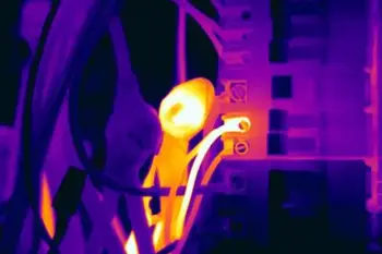
Thermography uses infrared imaging for non-contact thermal scanning, revealing hotspots in electrical panels, switchgear, and power distribution. It supports predictive maintenance, fault detection, and condition monitoring, reducing downtime and improving safety.
The Importance of Thermography in Electrical Safety
Thermography used to be expensive, difficult, and primarily used by large industrial facilities and the military. These days, it has become much more affordable, easier to use, and more broadly applied. Beyond industrial uses, facilities implementing load management often pair thermographic monitoring with thermal energy storage to optimize HVAC performance and reduce peak demand.A thermal imager works by producing thermal (heat)…
View more
Sign Up for Electricity Forum’s Software and Apps Newsletter
Stay informed with our FREE Software and Apps Newsletter — get the latest news, breakthrough technologies, and expert insights, delivered straight to your inbox.
5 Levels of PLC Proficiency
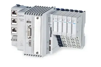
PLC proficiency drives industrial automation excellence with Programmable Logic Controllers, ladder logic, IEC 61131-3 languages, HMI/SCADA integration, I/O troubleshooting, safety circuits, PID tuning, and networked control for reliable, maintainable, and scalable electrical engineering systems.
Understanding PLC Proficiency: Principles and Applications
Ladder logic, a programming language used to primarily develop PLC software, was made for use in early PLCs because the symbology was similar to the printed ladder schematics already used to document relay control systems, so the transition to PLCs could be familiar and seamless. After all, electricians had to be the first ones to buy in to these…
View more


