Three Phase Transformer Connections
By Harold Williams, Associate Editor
By Harold Williams, Associate Editor
Our customized live online or in‑person group training can be delivered to your staff at your location.

Three Phase Transformer Connections configure windings in delta or wye to optimize voltage transformation, load balancing, and system reliability in power distribution networks.
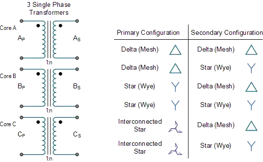
Large blocks of AC power are transmitted and distributed at high voltage levels through three-phase transformer connections. While it’s possible to connect three single-phase transformers to form a three-phase transformer bank, the standard approach is to integrate all three phase windings into a single core. This single-unit design offers:
Higher efficiency compared to three separate single-phase units.
Simpler busbar, switchgear, and wiring arrangements.
Reduced weight and space requirements.
Lower manufacturing cost due to reduced core material.
The main advantage of a transformer bank is fault tolerance. If one single-phase transformer in a bank fails, the remaining units can sometimes be reconfigured to provide partial service. In a single three-phase transformer, failure of one winding requires the entire unit to be removed from service. However, modern transformers are highly reliable, making three-phase units the norm. Three-phase distribution systems often rely on utility transformers to step voltage levels up or down for efficient transmission and delivery.
3-phase transformers are essential in power systems for efficiently transmitting and distributing electricity. Depending on the application, they can be built in different configurations, such as a delta transformer connection for robust performance under unbalanced conditions or a star star connected arrangement for providing a neutral point. Inside the unit, an iron core supports the magnetic coupling between windings, allowing precise control of phase voltages across the primary and secondary sides. While designed to supply balanced three-phase loads, these transformers can also serve a single phase load when properly connected. Understanding the various types of three phase transformer designs helps engineers choose the most efficient and reliable option for their specific requirements. Understanding the construction of transformer cores, windings, and insulation is essential when evaluating design and performance.
Think you know Utility Transformers? Take our quick, interactive quiz and test your knowledge in minutes.
Fig. 1. Delta-Delta three-phase distribution transformer connection showing primary and secondary windings on a shared core for balanced power delivery.
In many distribution networks, a distribution transformer serves as the final voltage step before electricity reaches the consumer.
Three-phase transformer connections are named according to how the primary and secondary windings are interconnected. For compact installations, a 3 phase pad mounted transformer provides a secure, ground-level solution for neighborhoods and commercial sites.
Delta-Delta (Δ-Δ)
No phase shift between primary and secondary.
Suitable for systems without a neutral connection.
Tolerates unbalanced loads reasonably well.
Wye-Wye (Y-Y)
No phase shift, but prone to third-harmonic distortion unless a delta tertiary winding is added.
Provides a neutral point for grounding.
Delta-Wye (Δ-Y)
Introduces a 30° phase shift between primary and secondary.
Secondary side provides a grounded neutral, useful for distribution.
Common in utility step-down applications.
Wye-Delta (Y-Δ)
Also introduces a 30° phase shift but in the opposite direction to Δ-Y.
Suitable for stepping voltage up in transmission systems.
Engineers selecting equipment can review our complete guide to 3 phase transformers to compare ratings, applications, and configurations.
Fig. 2. - Three-phase transformer windings on a laminated core, illustrating primary delta and secondary wye coil arrangements for voltage step-down.
When selecting specialized designs, medium voltage transformers can provide reliable service for industrial and utility applications.
| Connection Type | Phase Shift | Neutral Availability | Advantages | Limitations |
|---|---|---|---|---|
| Delta-Delta | 0° | No | Handles unbalanced loads well | No neutral |
| Wye-Wye | 0° | Yes | Neutral point for grounding | Harmonic distortion risk |
| Delta-Wye | +30° | Yes (secondary) | Common in step-down, grounded neutral | Phase shift requires attention |
| Wye-Delta | -30° | No | Common in step-up applications | No secondary neutral |
| Open-Delta | Varies | No | Allows temporary service with reduced capacity | Limited output (~58–87%) |
Each connection type produces a specific phase displacement between the primary and secondary voltages. This displacement is indicated in vector group notation (e.g., Yd11, Dy1). The first letter denotes the primary winding connection (Y for wye, D for delta), the second denotes the secondary connection, and the number indicates the phase shift in clock notation.
Example: Yd11 means a wye-connected primary, delta-connected secondary, with a 330° displacement (or -30° phase shift).
In the event of a single transformer failure in a delta-connected bank, an open-delta (V-V) connection can be used temporarily. This allows the system to continue operating at approximately 58–87% of its original capacity, depending on loading. This method provides short-term service continuity until repairs are made.
Fig. 3. Open-delta three-phase transformer bank created from single-phase units, used for temporary service during transformer faults.
Polarity (Dot Convention): Always observe correct polarity markings when connecting windings to avoid circulating currents or short circuits.
Voltage & Impedance Matching: When forming a transformer bank, ensure identical voltage ratings, kVA capacity, impedance, manufacturer, and model.
Grounding: For grounded systems, Wye-connected windings with a neutral point are preferred.
Balanced Loading: Strive for even load distribution across all phases to prevent overheating and performance degradation.
Update figure captions to be descriptive and SEO-friendly:
“Delta-Wye Connection Diagram – Showing Primary Delta and Secondary Wye Windings”
“Star-Delta Phasor Relationships – Phase Shift Illustration”
“Open-Delta Transformer Bank – Temporary Fault Operation”

Explore 50+ live, expert-led electrical training courses –