Unit of Capacitance Explained


Unit of Capacitance

The unit of capacitance is the farad (F), which measures the amount of electric charge a capacitor stores per volt. Typically expressed in microfarads, nanofarads, or picofarads, it is essential in electronics, circuit design, and energy storage systems.


What is a Unit of Capacitance?

The unit of capacitance, the farad (F), measures the amount of electric charge a capacitor can store per volt. It is crucial to understand the function of capacitors in electronics, circuits, and energy storage technologies.

✅ 1 farad equals 1 coulomb per volt

✅ Common values include microfarads, nanofarads, and picofarads

✅ Used in electronics, circuits, power systems, and capacitor design


It is determined by the electrical charge, which is symbolized by the letter Q, and is measured in units of coulombs. Discover how capacitance interacts with other electrical quantities and gain a deeper understanding of its role in circuit design and performance. The coulomb is given by the letter C, as with capacitance. Unfortunately, this can be confusing. One coulomb of charge is defined as a charge equivalent to 6.28 × 10^18 electrons. The basic unit is the farad, denoted by the letter F. By definition, one farad is the amount of charge stored on a capacitor when one volt is applied across its plates. The general formula for capacitance in terms of charge and voltage is:


Understanding the Unit of Electric Capacitance
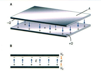
The unit of electric capacitance explains how a capacitor functions as a body to store an electrical charge. This is achieved through two conductive plates, which form the essential structure of a parallel plate capacitor. These plates are separated by an insulating material, known as the dielectric, which prevents direct current flow while allowing the device to store energy.

A capacitor is a widely used electronic component, and it belongs to the class of passive electronic components since it does not generate energy but only stores it temporarily. The concept of capacitance was first defined by the English physicist Michael Faraday, whose pioneering work in electromagnetism laid the foundation of electrical science. Historical records place Michael Faraday 1791 1867 as one of the most influential figures in this field.

In modern practice, capacitance is measured in the SI base units of the farad (F). Because a farad is large, smaller units such as the nanofarad nF are commonly used to describe practical capacitors found in circuits. Whether measured in farads, microfarads, or nanofarads, the unit of electric capacitance remains the standard way of expressing a capacitor’s ability to store charge for reliable operation in electronic systems.


Farad in Practical Use

In practical terms, one farad is a large amount of capacitance. Typically, in electronics, much smaller units are used. The two more common smaller units are the microfarad (μF), which is 10^-6 farad, and the picofarad (pF), which is 10^-12 farad. To better understand the core principles behind charge and voltage, see our overview on what is a capacitor, which explains how capacitance functions in practical circuits.

Voltage Rating of a Capacitor: Capacitors have limits on the voltage that can be applied across their plates. The aircraft technician must be aware of the voltage rating, which specifies the maximum DC voltage that can be applied without risking damage to the device. This voltage rating is typically referred to as the breakdown voltage, working voltage, or simply the voltage rating. If the voltage applied across the plates is too great, the dielectric will break down, and arcing will occur between the plates. The capacitor is then short-circuited, and the possible flow of direct current through it can cause damage to other parts of the equipment. For foundational knowledge that supports capacitance calculations, our what is voltage article defines the relationship between electric potential and stored charge.

A capacitor that can be safely charged to 500 volts DC cannot be safely subjected to AC or pulsating DC whose effective values are 500 volts. An alternating voltage of 500 volts (RMS) has a peak voltage of 707 volts, and a capacitor to which it is applied should have a working voltage of at least 750 volts. The capacitor should be selected so that its working voltage is at least 50 percent greater than the highest voltage to be applied. Learn about different types of components that influence total capacitance by reading our guide on types of capacitors, which compares materials, ratings, and applications.


Smaller Units of Capacitance

The voltage rating of the capacitor is a factor in determining the actual capacitance, as capacitance decreases with increasing dielectric thickness. A high-voltage capacitor with a thick dielectric must have a larger plate area to achieve the same capacitance as a similar low-voltage capacitor with a thin dielectric.


Table 1 – Dielectric Strength of Common Materials

Dielectric Material Approx. Dielectric Strength (kV/mm) Relative Permittivity (εr) Notes / Applications
Vacuum 30 1.0 Reference value, ideal insulator
Air 3 ~1.0 Baseline, used as standard
Paper 16 3–4 Used in older capacitors
Glass 9–14 4–10 High stability, low loss
Mica 100 5–7 Precision capacitors, RF use
Ceramic 10–40 6–12 (varies) Common in small capacitors
Polystyrene 20–30 2.5–2.7 Low loss, stable
Polyethylene 20–30 2.2 High-voltage applications
Teflon (PTFE) 60–170 2.1 Excellent insulator, stable
Oil (transformer) 10–15 2.2–2.3 Used in HV capacitors and transformers
Quartz 8–10 ~3.8 Stable, heat resistant


Factors Affecting A Unit of Capacitance

  1. The capacitance of parallel plates is directly proportional to the area of the plates. A larger plate area produces a larger capacitance, and a smaller area produces less capacitance. If we double the area of the plates, there is room for twice as much charge. The charge that a capacitor can hold at a given potential difference is doubled, and since C = Q/E, the capacitance is doubled.

  2. The capacitance of parallel plates is inversely proportional to the spacing between them.

  3. The dielectric material affects the capacitance of parallel plates. The dielectric constant of a vacuum is defined as 1, and that of air is very close to 1. These values are used as a reference, and all other materials have values specified in relation to air (vacuum).

The strength of some commonly used dielectric materials is listed in Table 1. The voltage rating also depends on frequency, as the losses and resultant heating effect increase with higher frequencies. Discover how capacitance fits into the broader context of energy flow in circuits by visiting our what is electrical resistance page, offering insights on resistance and its effect on voltage and current.

Related News

What is a Watt? Electricity Explained

A watt is the standard unit of power in the International System of Units (SI). It measures the rate of energy transfer, equal to one joule per second. Watts are commonly used to quantify electrical power in devices, circuits, and appliances.


What is a Watt?

A watt is a unit that measures how much power is used or produced in a system. It is central to understanding electricity and energy consumption.

✅ Measures the rate of energy transfer (1 joule per second)

✅ Commonly used in electrical systems and appliances

✅ Helps calculate power usage, efficiency, and energy costs

A watt is a unit of power, named after engineer James Watt, which measures the rate of energy transfer. A watt is a unit of power that measures the rate at which energy flows or is consumed. One watt is equivalent to one joule per second. In terms of electrical usage, 1,000 watt hours represent the amount of energy consumed by a device using 1,000 watts over one hour. This concept is important for understanding power consumption across devices on the electric grid. The watt symbol (W) is commonly used in electricity to quantify power, and watts measure power in various contexts, helping to track energy flow efficiently.


Frequently Asked Questions

How does a watt relate to energy?

A watt is a unit of power that measures the rate at which energy is consumed or produced. Specifically, one watt equals one joule per second, making it a crucial unit in understanding how energy flows.


How is a watt different from a watt-hour?

A watt measures power, while a watt-hour measures energy used over time. For instance, if you use a 100-watt bulb for 10 hours, you've consumed 1,000 watt-hours of energy.


How many watts does a typical household appliance use?

Wattage varies between appliances. For example, a microwave uses 800 to 1,500 watts, while a laptop typically uses between 50 to 100 watts. Understanding the wattage helps estimate overall power consumption.


What does it mean when a device is rated in watts?

A device’s watt rating indicates its power consumption when in use. A higher wattage means the device draws more power, leading to higher energy costs if used frequently.


How can I calculate power consumption in watts?

To calculate power in watts, multiply the voltage (volts) by the current (amperes). For example, a device using 120 volts and 10 amps will consume 1,200 watts. A watt, in electrical terms, is the rate at which electrical work is done when one ampere (A) of current flows through one volt (V). Formula:

W= A* V

Whenever current flows through a resistance, heat results. This is inevitable. The heat can be measured in watts, abbreviated W, and represents electrical power. Power can be manifested in many other ways, such as in the form of mechanical motion, or radio waves, or visible light, or noise. In fact, there are dozens of different ways that power can be dissipated. But heat is always present, in addition to any other form of power in an electrical or electronic device. This is because no equipment is 100-percent efficient. Some power always goes to waste, and this waste is almost all in the form of heat.

There is a certain voltage across the resistor, not specifically given in the diagram. There's also electricity flowing through the resis­tance, not quantified in the diagram, either. Suppose we call the voltage E and the cur­rent I, in volts and amperes, respectively. Then the power in watts dissipated by the resistance, call it P, is the product E X I. That is:

P (watts) = El

This power might all be heat. Or it might exist in several forms, such as heat, light and infrared. This would be the state of affairs if the resistor were an incandescent light bulb, for example. If it were a motor, some of the power would exist in the form of me­chanical work.

If the voltage across the resistance is caused by two flashlight cells in series, giving 3 V, and if the current through the resistance (a light bulb, perhaps) is 0.1 A, then E = 3 and I = 0.1, and we can calculate the power P, in watts, as:

P (watts) = El = 3 X 0.1 = 0.3 W

Suppose the voltage is 117 V, and the current is 855 mA. To calculate the power, we must convert the current into amperes; 855 mA = 855/1000 = 0.855 A. Then we have: 

P (watts) = 117 X 0.855 = 100 W

You will often hear about milliwatts (mW), microwatts (uW), kilowatts (kW) and megawatts (MW). You should, by now, be able to tell from the prefixes what these units represent. But in case you haven't gotten the idea yet, you can refer to Table 2- 2. This table gives the most commonly used prefix multipliers in electricity and electron­ics, and the fractions that; they represent. Thus, 1 mW = 0.001 W; 1 uW = 0.001 mW = 0.000001 W; 1 kW = 1-flOO W; and 1 MW = 1,000 kW = 1,000, 000 W.

Sometimes you need to use the power equation to find currents or voltages. Then you should use I = P/E to find current, or E = P/I to find power. It's easiest to remem­ber that P = El (watts equal volt-amperes), and derive the other equations from this by dividing through either by E (to get I) or by I (to get E).

A utility bill is measured in kilowatt hours, usually in 1,000 watt increments. A watt is a unit of electrical energy in which the units of measurement (watts and watt hours) are agreed to by an international system of units si called watts. The amout of energy is measured this way.


Related Articles


View more

What is a Ground Fault? Hazard Explained

A ground fault occurs when electrical current unintentionally flows to the ground, often through a person or conductive surface. It poses serious shock and fire hazards and typically results from damaged wiring, insulation failure, or water intrusion in electrical systems.


What is a Ground Fault?

A ground fault is a potentially hazardous electrical event when an unintended electrical path forms between a live electrical conductor and a grounded surface.

✅ Occurs when electrical current flows to ground through an unintended path

✅ Commonly caused by damaged wires, insulation failure, or moisture

✅ Increases the risk of electrical shock and equipment failure

The flow of current through this unintended path, also known as earth leakage, can cause serious electrical shock hazards and damage to electrical systems. Let's examine the causes, dangers, and preventive measures associated with ground faults. Proper electrical grounding is essential to prevent ground faults, as it ensures that stray currents are safely diverted into the earth. 

There are common causes of ground faults. A ground fault occurs because of several factors, including damaged insulation, incorrect wiring, or moisture in the electrical system. Damaged insulation, for example, can expose the conductor of electricity, allowing it to come into contact with a grounded surface. Additionally, moisture can create a conductive path between live conductors and the earth, thereby increasing the risk. Moisture intrusion and damaged insulation can cause faults similar to arc faults, which are discussed further in our power quality troubleshooting resource.

One of the primary dangers associated with ground faults is the risk of electrical shock. When one occurs, it can create a path to the earth through a person, leading to serious injury or even death. Additionally, they can cause overheating, sparking, and fires in electrical systems, posing a significant risk to property and life.

Ground fault circuit interrupters (GFCIs) are essential devices designed to mitigate the risks associated with ground faults. GFCIs constantly monitor the flow of electrical current between the hot wire and the neutral wire. If an imbalance is detected, the GFCI quickly cuts power to the electrical circuit, preventing electrical shock and minimizing potential damage. GFCI outlets are commonly installed in areas where water is present, such as kitchens, bathrooms, and outdoor spaces, as these locations have a higher risk of ground faults. A grounding system should be regularly inspected to minimize the risk of fire and shock caused by unintentional current paths.


Preventing Ground Faults

Preventing and minimizing ground faults involves several steps. First, proper electrical grounding is critical in reducing the risk. A grounding wire connected to the electrical box creates a path for fault current to flow safely to the earth, reducing the likelihood of electrical shock. Regular inspection and maintenance of electrical systems can also help identify potential issues, such as damaged insulation or incorrect wiring, before they lead to ground faults. Additionally, using GFCI-protected outlets and circuit breakers in high-risk areas can help prevent ground faults and protect against shock hazards.

Understanding the differences between ground faults, short circuits, and arc faults is important, as they are all distinct electrical events with unique risks and causes. A short circuit occurs when a live conductor comes into contact with a neutral or grounded conductor, resulting in a sudden surge of current. This can lead to overheating, fires, or damage to electrical equipment. On the other hand, arc faults occur when an electrical arc forms between conductors, often due to damaged or frayed wiring. Arc faults can generate excessive heat and pose a fire risk.

Identifying one in an electrical system can be accomplished through visual inspection, testing, or the use of specialized equipment. For example, signs of a ground fault may include tripped GFCI outlets or circuit breakers, flickering lights, or a burning smell near electrical equipment. Additionally, testing outlets with a ground fault circuit interrupter tester or a multimeter can help determine if a ground fault is present.

Grounding is crucial in preventing ground faults and protecting against electrical shock. By providing a safe path for fault current to flow, earthing helps minimize the risk of injury and damage to electrical systems. Proper earthing involves connecting all electrical equipment, including outlets, switches, and metal boxes, to a grounding wire connected to the earth. This connection helps ensure that unintended electrical paths, such as those caused by ground faults, are safely grounded.


Understanding Ground Faults

Understanding what a ground fault is and how to prevent it is essential for ensuring electrical safety in residential and commercial settings. Proper earthing, regular inspection and maintenance of electrical systems, and the use of GFCI-protected outlets and circuit breakers are all crucial measures in reducing the risk of electrical hazards. By being aware of the dangers associated with ground faults and taking proactive steps to address them, we can help protect our homes, businesses, and loved ones from electrical hazards.

In addition to the precautions mentioned above, it's essential to exercise caution when using power tools and appliances. Many incidents occur when using power tools in damp environments. Always ensure that power tools are in good working condition, with no frayed cords or damaged insulation. Use GFCI-protected outlets or extension cords when operating them in potentially hazardous conditions.

Moreover, educating yourself and those around you about electrical safety is crucial. Understanding the risks associated with ground faults and knowing how to respond in an electrical emergency can save lives. Regularly reviewing safety procedures and ensuring that everyone in your home or workplace knows how to use GFCI outlets and reset buttons. Circuit breakers can significantly reduce the risk of injury or property damage.

Finally, don't hesitate to consult a licensed electrician if you suspect or encounter any electrical issues. Professional electricians have the knowledge and tools to diagnose and repair electrical problems safely and effectively. Attempting to resolve electrical issues without proper training can be dangerous and may lead to further complications.

By adopting a comprehensive approach to electrical safety, we can minimize risks and create a safer environment for ourselves and our communities. Awareness, preventive measures, and education are crucial in reducing the incidence of injuries and ensuring the well-being of everyone interacting with electrical systems.


Related Articles


View more

What is Considered High Voltage? HV Applications Explained

What is considered high voltage? Per IEC/IEEE, voltages above 1 kV AC or 1.5 kV DC; linked to insulation coordination, arc-flash risk, transmission lines, substations, switchgear ratings, clearance/creepage distances, and dielectric breakdown in power systems.


What Is Considered High Voltage?

Voltages above 1 kV AC or 1.5 kV DC are classed as high voltage per IEC/IEEE in power systems.

✅ IEC/IEEE: >1 kV AC or >1.5 kV DC thresholds

✅ Categories: MV, HV, EHV, UHV in power transmission

✅ Impacts insulation, clearance, arc-flash, switchgear ratings


What is Considered High Voltage?

In the world of electrical engineering, understanding voltage levels is crucial. So you might be asked to define high voltage. But what is considered HV? This article explores the definition, classification, and applications of HV and the safety concerns and precautions that come with it. For foundational context, the concept of voltage underpins how these levels are defined and compared across systems.


According to the International Electrotechnical Commission (IEC), HV is typically defined as any voltage above 1000 volts for alternating current (AC) systems and 1500 volts for direct current (DC) systems. However, the term "HV" can also refer to voltages as low as 50 volts in some safety regulations, depending on the context. For example, the US Occupational Safety and Health Administration (OSHA) defines HV as 600 volts or higher in their safety guidelines. Standards often reference nominal voltage values that guide equipment ratings, insulation clearances, and test criteria in practice.

High voltage systems are essential in electric power transmission and distribution, allowing electricity to be transported over long distances with minimal energy loss. Power lines, transmission lines, and transformers all play a role in the power transmission and distribution process. Transformers are used to step up or down voltage levels, depending on whether the electricity is transported over long distances or distributed to end-users. At the point of use, networks step down to low voltage levels suitable for residential and commercial equipment before final delivery.

Voltage classification is a method for organizing voltages based on their range. There are four primary classifications of voltage levels: low (LV), medium  (MV), HV, and extra HV (EHV). Ultra HV (UHV) is another classification for exceptionally high voltages, typically used in long-distance power transmission projects. In distribution grids, medium voltage tiers bridge the gap between long-distance transmission and local feeders in a coordinated hierarchy.

Insulation is a crucial aspect of HV systems, as it prevents electrical current from leaking and causing short circuits, equipment damage, or even fires. Different types of insulation are used depending on the voltage level and application, such as air, gas, oil, or solid materials like plastics and ceramics. For clarity on terminology used in insulation, dielectric strength, and creepage distances, consult common electricity terms that standardize communication across projects.

HV circuits and equipment, such as transformers and switchgear, are designed to handle higher voltages safely and efficiently. These devices are essential components of power distribution networks and are subject to strict design, manufacturing, and testing standards to ensure reliability and safety.

Working with high voltage circuits presents several electrical hazards, such as electric shock, arc flash, and fires. To mitigate these risks, electrical safety measures must be put in place. Workers with HV equipment must follow safety procedures and use appropriate personal protective equipment (PPE), such as insulated gloves, safety glasses, and arc flash suits. Comprehensive electricity safety programs integrate procedures, labeling, lockout/tagout, and training to reduce incident rates.

So, what is considered high voltage? As mentioned earlier, the IEC defines HV as 1000 volts for AC and 1500 volts for DC. However, some safety regulations might consider voltages as low as 50 or 600 volts as HV.

HV is used in power transmission and distribution to transport electricity efficiently over long distances. Transmission lines, transformers, and other equipment are designed to handle HVs and are integral to power distribution networks.

Safety concerns associated with HV systems include electric shock, arc flash, and fires. Proper safety procedures and protective equipment are necessary to minimize these risks. Understanding the broader dangers of electricity helps contextualize HV-specific risks and informs mitigation strategies.

Transformers handle HV levels by stepping up or stepping down the voltage, allowing for efficient power transmission and distribution. They are designed to withstand HV stresses and are subject to rigorous testing and standards.

Various types of insulation are needed for HV applications, including air, gas, oil, and solid materials like plastics and ceramics. The choice of insulation depends on the level and specific application requirements.

The different classifications of voltage levels include low, medium, HV, extra HV, and ultra HV. These classifications help categorize voltage ranges for various applications and safety standards.

When working with HV equipment, workers should follow safety procedures, use appropriate personal protective equipment, and undergo regular training to stay updated on best practices and safety guidelines.

In conclusion, understanding what is considered HV is crucial for electrical systems' safe and efficient operation. HV plays a vital role in power transmission and distribution, allowing electricity to be transported over long distances with minimal losses. Proper insulation, transformers, and other equipment are designed to handle HV levels and ensure the reliability of the electrical infrastructure. Safety concerns associated with HV systems must be addressed through stringent safety procedures, protective equipment, and worker training. We can maintain a safe and efficient electrical infrastructure by adhering to these guidelines and understanding the importance of classifications.


High, Extra-High and Ultra-HV Classifications

High, extra-high, and ultra-high voltage classifications are categories used to define the levels within electrical systems, particularly in power transmission and distribution networks. These classifications help standardize the design, manufacturing, and operation of electrical equipment and ensure safety and efficiency.


High Voltage (HV):

HV is typically defined as levels between 1000 volts (1 kV) and 100,000 volts (100 kV) for alternating current (AC) systems and between 1500 volts (1.5 kV) and 100,000 volts (100 kV) for direct current (DC) systems. HV systems are commonly used in electric power transmission and distribution networks, substations, and industrial facilities. HV allows for efficient power transmission over long distances while reducing energy loss due to resistance.


Extra-High Voltage (EHV):

Extra-high voltage refers to levels above 100,000 volts (100 kV) and up to 300,000 volts (300 kV) for AC systems and between 100,000 volts (100 kV) and 800,000 volts (800 kV) for DC systems. EHV systems are primarily used for long-distance power transmission, where higher levels reduce energy losses even further. EHV lines and equipment require specialized design, manufacturing, and maintenance to ensure safety, reliability, and efficiency. The use of extra-high voltage is also associated with more stringent safety protocols and larger right-of-way requirements for transmission lines.


Ultra-High Voltage (UHV):

Ultra-high voltage classification is designated for levels above 300,000 volts (300 kV) for AC systems and above 800,000 volts (800 kV) for DC systems. UHV systems are used in large-scale power transmission projects that aim to transmit massive amounts of electricity over very long distances with minimal losses. These projects typically connect major power generation sources, such as hydroelectric or nuclear plants, to far-off load centers or densely populated urban areas. As a result, UHV systems demand the highest level of engineering expertise, rigorous testing, and specialized equipment to ensure their safe and efficient operation.


Related Articles

View more

How to Save Electricity?

How to save electricity? Improve energy efficiency, switch to LED lighting, manage standby power, use smart thermostats, insulate homes, schedule heavy appliances off-peak, and conduct energy audits to cut power consumption and lower bills.


How to Save Electricity?

Reduce power consumption with LEDs, smart thermostats, insulation, and off-peak usage to lower energy bills.

✅ Upgrade to LED lighting and ENERGY STAR appliances

✅ Program smart thermostats; set HVAC to efficient ranges

✅ Eliminate standby power with advanced power strips


How to Save Electricity is a popular question. It involves energy conservation and lessens real dollars and preserves a public resource. Here are some ways to cut energy costs without compromising your lifestyle too much. For a deeper primer on cutting household consumption, explore this saving electricity guide for actionable steps.


Control heating and cooling costs

In some climates, heating and cooling represent the largest part of household energy use. In many climates, running your air conditioner at 78 instead of 72 will earn 40% of your cooling bill. You don't have to freeze or roast to death in order to use less energy and earn money. In some climates, heating and cooling represent the largest part of household energy use. In many climates, running your air conditioner at 78 instead of 72 will earn 40% of your cooling bill. You don't have to freeze or roast to death in order to use less energy and earn money.In some climates, heating and cooling represent the largest part of household energy use. In many climates, running your air conditioner at 78 instead of 72 will earn 40% of your cooling bill. You don't have to freeze or roast to death in order to use less energy and earn money. Here are a few tips:

Understanding how HVAC loads draw electric power can help you schedule operation during cooler periods for efficiency.

  • How to Save Electricity? Make sure your filters are clean. Check with the manufacturer of your equipment or with your utility company to see if filters on your units need to be cleaned.
  • Don't heat or cool when no one is home. If you are going to be gone for more than a half an hour, you can turn your heating or cooling off or down. Don't turn off the heat in a cold climate because that may result in the pipes breaking.
  • Supplement your main unit with portable units Running a fan can help you use less air conditioning. Using portable heaters when you are asleep or otherwise staying in one room can mean less use of heat if it means that you don't have to use the main unit.
  • Try setting your thermostat to run less frequently Turn your air conditioner up a degree or two or your heater down a degree or two and see if you still can be comfortable.
  • Time your opening and closing of windows and drapes to reduce heading and cooling costs. On cold, sunny days, opening curtains and drapes while leaving windows closed will help you heat your home. Opening the windows on summer nights helps cool your home. Buying storm windows in some climates reduces heating costs.
  • Check for holes in your roof and in your pipes. This can help reduce up to 10 per cent of your heating and cooling costs.

Track your improvements by reading your electricity meter regularly and noting weekday versus weekend patterns.


Get energy saving ideas from your utility company 

Utility companies are among the few businesses who hope that you use less of their product. Most power companies are anxious to postpone construction of new power plants, so they strongly encourage customers to use less power. 
Utility companies offer energy audits, tips, and other help for customers who want to reduce energy consumption. Call your local utility or log onto their website to see what they have to offer. Many utilities explain how electricity cost components like demand and time-of-use rates affect bills.


Other Electricity Saving tips:

  • Consider how to increase your energy efficiency when buying appliances Appliances are labeled with energy usage comparison tables. Look at these figures. Also, you may be able to buy an adapter to make your older appliances more energy efficient.
  • Turn off appliances that no one is using Turning off TV's, lamps, computers, VCR's, ovens, and other appliances that no one is using can reduce electric energy consumption. Even turning them off for short periods can produce noticeable results.
  • See if an alternative energy company is available In California, electrical deregulation is beginning to result in alternative providers of electric power. This is a trend that should increase nationally. See if that option is available to you.
  • Install low-flow heads in your water closets. Also, check your water heater's temperature and set it for 120 degrees. Putting insulation over your water heater and pipes can also help.
  • Wash and dry only full loads of clothing or dishes

Stay aware of regional electricity prices so you can plan high-use activities for lower-cost periods.

You may not make you rich, but it will help you cut down some on your costs and will help prevent blackouts and power shortages in your community.

Are your company's profits being eroded by escalating energy costs? Can you gamble that your energy costs will go down in the future? What are you doing about preparing and protecting your company from spiraling energy costs?

If you operate in competitive markets, review how electricity deregulation shapes supplier choices and contract terms.

Do you have the knowledge of the dynamic market with the right equipment that will make the 'smart decisions' and make an effective difference in your energy consumption and see your energy bill go down?

Facilities with inductive loads can cut charges by improving power factor through correction equipment and better motor controls.


Do you know about the latest technologies that you can implement now?

These questions can be answered by our new Industrial, Commercial & Institutional Energy Efficiency Handbook. This 100+ page book is jammed with practical information on reducing energy consumption, increase Energy efficiency by using modern technologies such as variable frequency drives, high efficiency electrical devices, energy efficient lighting, energy management control systems, metering and management systems, as well as fan, pump and blower efficiency improvements. We will also list Federal, State, utility and Canadian government programs that will reduce your energy consumption and increase your energy efficiency.


Related Articles

View more

Electricity How it Works

Electricity How It Works explains electron flow, voltage, current, resistance, and power in circuits, from generation to distribution, covering AC/DC systems, Ohm's law, conductors, semiconductors, transformers, and energy conversion efficiency and safety.


What Is Electricity How It Works?

Explains electron flow, voltage, current, resistance, and power conversion in AC/DC circuits and key components.

✅ Voltage drives current through resistance per Ohm's law (V=IR).

✅ AC/DC systems distribute power via transformers and rectifiers.

✅ Conductors, semiconductors, capacitors, inductors shape circuits.


Electricity How It Works - This is a very common question. It can best be explained by stating this way: Single-phase electricity is what you have in your house. You generally talk about household electrical service as single-phase, 120-volt AC service. If you use an oscilloscope and look at the power found at a normal wall-plate outlet in your house, what you will find is that the power at the wall plate looks like a sine wave, and that wave oscillates between -170 volts and 170 volts (the peaks are indeed at 170 volts; it is the effective (rms) voltage that is 120 volts). The rate of oscillation for the sine wave is 60 cycles per second. Oscillating power like this is generally referred to as AC, or alternating current. The alternative to AC is DC, or direct current. Batteries produce DC: A steady stream of electrons flows in one direction only, from the negative to the positive terminal of the battery.

For a refresher on fundamentals, the overview at what is electricity explains charge, current, and voltage in practical terms.

AC has at least three advantages over DC in an electricity power distribution grid:

1. Large electricity generators happen to generate AC naturally, so conversion to DC would involve an extra step.
2. Electrical Transformers must have alternating current to operate, and we will see that the power distribution grid depends on transformers. 
3. It is easy to convert AC to DC but expensive to convert DC to AC, so if you were going to pick one or the other AC would be the better choice.

To connect these advantages to real-world practice, the primer on basic electricity clarifies AC versus DC behavior, impedance, and safety basics.

The electricity generating plant, therefore, produces AC. For a deeper look at how rotating machines induce AC, see the overview of electricity generators and their role in utility-scale plants.


Electricity How it Works in The Power Plant: Three-phase Power

If you want a quick walkthrough from generation to loads, this guide on how electricity works ties the concepts together before we examine three-phase specifics.

The power plant produces three different phases of AC power simultaneously, and the three phases are offset 120 degrees from each other. There are four wires coming out of every power plant: the three phases plus a neutral or ground common to all three. If you were to look at the three phases on a graph, they would look like this relative to ground:

A concise visual explainer on three-phase electricity shows how 120-degree phase offsets create balanced currents in feeders.

Electricity How It Works - There is nothing magical about three-phase power. It is simply three single phases synchronized and offset by 120 degrees. For wiring diagrams and common configurations, explore 3-phase power examples used across industrial facilities.

Why three phases? Why not one or two or four? In 1-phase and 2-phase electricity, there are 120 moments per second when a sine wave is crossing zero volts. In 3-phase power, at any given moment one of the three phases is nearing a peak. High-power 3-phase motors (used in industrial applications) and things like 3-phase welding equipment therefore have even power output. Four phases would not significantly improve things but would add a fourth wire, so 3-phase is the natural settling point.

Practical comparisons of motor torque ripple and line loading in 3-phase electricity help illustrate why three conductors strike the best balance.

And what about this "ground," as mentioned above? The power company essentially uses the earth as one of the wires in the electricity system. The earth is a pretty good conductor and it is huge, so it makes a good return path for electrons. (Car manufacturers do something similar; they use the metal body of the car as one of the wires in the car's electrical system and attach the negative pole of the battery to the car's body.) "Ground" in the power distribution grid is literally "the ground" that's all around you when you are walking outside. It is the dirt, rocks, groundwater, etc., of the earth.


Related Articles

View more

What is Inductance?

Inductance is the property of an electrical circuit that resists changes in current by storing energy in a magnetic field. It underpins transformers, motors, inductors, and AC power systems, making it essential in the field of electrical engineering.


What is Inductance?

Inductance is a fundamental electrical property that describes how circuits resist changes in current flow by generating a magnetic field.

✅ Opposes changes in current by storing energy in a magnetic field

✅ Measured in henrys (H), used in inductors and transformers

✅ Essential in AC power systems, filters, and motor design

This principle is central to electromagnetic induction and underlies many devices in modern power and electronics.

The principle of inductance was first discovered by Michael Faraday, who showed that moving a magnet through a coil of wire induced a voltage across the coil. This discovery, known as Faraday’s Law, explains the phenomenon of electromagnetic induction. Heinrich Lenz later refined this understanding, demonstrating that the induced voltage always acts to oppose the change that created it — a principle now known as Lenz’s Law. These discoveries underpin the operation of inductors, transformers, and motors.

Inductance occurs when a change in current flow is utilized to prevent signals with a higher frequency component from passing, while allowing signals with lower frequency components to pass. This is why inductors are sometimes referred to as "chokes," as they effectively block higher frequencies. A common application of a choke is in a radio amplifier biasing circuit, where the collector of a transistor needs to be supplied with a DC voltage without allowing the RF (radio frequency) signal to conduct back into the DC supply. To understand how inductance interacts with voltage changes in AC circuits, see our article on voltage.

To understand how inductance interacts with voltage changes in AC circuits, see our article on voltage.

Power Quality Analysis Training

Power Factor Training

Request a Free Power Quality Training Quotation

Imagine a wire 1,000,000 miles (about 1,600,000 kilometres) long. Imagine that we form this wire into a huge loop and then connect its ends to the terminals of a battery, as shown in Figure 1, to drive current through the wire. Inductors are often paired with capacitors in circuits, so it's helpful to review the basics of what is a capacitor and how they function.

If we used a short wire for this experiment, the current would begin to flow immediately and attain a level limited only by the resistance in the wire and the resistance in the battery. But because we have an extremely long wire, the electrons require some time to work their way from the negative battery terminal, around the loop, and back to the positive terminal. Therefore, it will take some time for the current to reach its maximum level. Since inductance is used to oppose changes in current, our guide on what is current electricity provides essential background.

The magnetic field produced by the loop will initially be small during the first few moments when current flows only in part of the loop. The field will build up as the electrons get around the loop. Once the electrons reach the positive battery terminal, allowing a steady current to flow around the entire loop, the magnetic field quantity reaches its maximum and levels off, as shown in Figure 2. At that time, we'll have a certain amount of energy stored in the magnetic field. The amount of stored energy will depend on the inductance of the loop, which depends on its overall size. We symbolize inductance, as a property or as a mathematical variable, by writing an italicized, uppercase letter L. Our loop constitutes an inductor. To abbreviate "inductor," we write an upper-case, non-italicized letter L.


Fig. 1. We can use a huge, imaginary loop of wire to illustrate the principle of inductance.


Counter EMF and the RL Time Constant

As current begins to flow in a conductor, the expanding magnetic field induces a counter-electromotive force (emf) that opposes the applied voltage. At the instant of starting, this counter emf nearly equals the source voltage, keeping the current flow small. As the magnetic field stabilizes, the counter emf weakens until the current reaches its maximum.

Because inductors resist changes in current, the current in an RL circuit cannot change instantly. The rate of change is governed by the time constant (τ):

  • After one time constant, the current reaches approximately 63% of its maximum value.

  • After 5 time constants, the current is essentially steady.

This exponential buildup parallels the charging process of capacitors in RC circuits.


Building Inductance with Coils and Cores

Obviously, we can't make a wire loop measuring anywhere near 1,000,000 miles in circumference. But we can wind fairly long lengths of wire into compact coils. When we do that, the magnetic flux for a given length of wire increases compared with the flux produced by a single-turn loop, increasing the inductance. If we place a ferromagnetic rod, called a core, inside a coil of wire, we can increase the flux density and further enhance the inductance. High-frequency signals blocked by inductors are often explained using the concept of impedance, detailed in our page on what is impedance.

We can achieve values of L many times greater with a ferromagnetic core than with a similar-sized coil having an air core, a solid plastic core, or a solid wooden core. (Plastic and dry wood have permeability values that differ little from air or a vacuum; engineers occasionally use these materials as coil cores or "forms" to add structural rigidity to the windings without significantly changing the inductance.) The current that an inductor can handle depends on the diameter of the wire. But the value of L also depends on the number of turns in the coil, the diameter of the coil, and the overall shape of the coil. Many circuits involve a balance between resistance and inductance, so reviewing what is electrical resistance will add depth to your understanding.

Key physical parameters that affect inductance include:

  • Number of turns: inductance varies as the square of the turns.

  • Cross-sectional area: a larger area increases inductance.

  • Length of the coil: Longer coils reduce inductance.

  • Core material: magnetic materials (iron, steel, nickel) concentrate flux and increase inductance.

If we hold all other factors constant, the inductance of a helical coil increases in direct proportion to the number of turns of wire. Inductance also increases in direct proportion to the diameter of the coil. If we "stretch out" a coil with a certain number of turns and a certain diameter while holding all other parameters constant, its inductance decreases. Conversely, if we "squash up" an elongated coil while holding all other factors constant, the inductance goes up. For insight into how inductors shape power quality, especially reactive power, read our overview of reactive power.


Self-Inductance

Even a straight conductor exhibits some inductance, but when the current in a coil changes, the change in the magnetic field induces a voltage across that same coil. This phenomenon is known as self-inductance, and it always opposes changes in current. The effect is central to the operation of inductors, transformers, and motor windings.


Normal and Abnormal Conditions

Under normal circumstances, the inductance of a coil (or any other type of device designed to function as an inductor) remains constant regardless of the strength of the signal we apply. In this context, "abnormal circumstances" refer to an applied signal so strong that the inductor wire melts or the core material overheats excessively. Good engineering sense demands that such conditions should never arise in a well-designed electrical or electronic system.


Fig. 2. Relative magnetic flux in and around a huge loop of wire connected to a current source, as a function of time.


Related Articles


View more

Sign Up for Electricity Forum’s Newsletter

Stay informed with our FREE Newsletter — get the latest news, breakthrough technologies, and expert insights, delivered straight to your inbox.

Electricity Today T&D Magazine Subscribe for FREE

Stay informed with the latest T&D policies and technologies.
  • Timely insights from industry experts
  • Practical solutions T&D engineers
  • Free access to every issue

Live Online & In-person Group Training

Advantages To Instructor-Led Training – Instructor-Led Course, Customized Training, Multiple Locations, Economical, CEU Credits, Course Discounts.

Request For Quotation

Whether you would prefer Live Online or In-Person instruction, our electrical training courses can be tailored to meet your company's specific requirements and delivered to your employees in one location or at various locations.