What is Electricity?
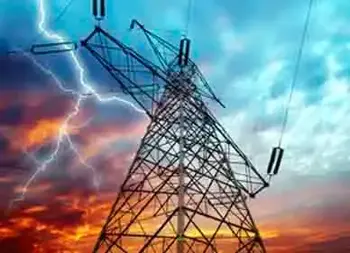

what is electricity

Electricity is the flow of electric charge, usually through a conductor like wire. It powers lights, appliances, and machines by converting energy into motion, heat, or light. Electricity can be generated from sources such as fossil fuels, wind, solar, or water.


What is electricity?

Electricity is a fundamental form of energy created by the movement of electrons.

✅ Powers homes, industries, and electronic devices

✅ Flows through circuits as an electric current

✅ Generated from renewable and non-renewable sources

The power we use is a secondary energy source because it is produced by converting primary energy sources such as coal, natural gas, nuclear, solar, and wind energy into electrical power. It is also referred to as an energy carrier, meaning it can be converted into other forms of energy, such as mechanical or thermal energy.

Primary energy sources are either renewable or nonrenewable, but our power is neither.

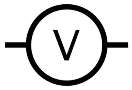
To understand why electrons move in the first place, start with voltage, the electrical “pressure” that pushes charge through every circuit.


Electricity Has Changed Everyday Life

Although most people rarely think about electricity, it has profoundly changed how we live. It is as essential as air or water, yet we tend to take it for granted—until it’s gone. Electricity powers heating and cooling systems, appliances, communications, entertainment, and modern conveniences that past generations never imagined.

Before widespread electrification began just over a century ago, homes were lit with candles or oil lamps, food was cooled with ice blocks, and heating was provided by wood- or coal-burning stoves.

The steady stream of electrons we use daily is explored in our primer on current electricity.


Discovering Electricity: From Curiosity to Power Grid

Scientists and inventors began unlocking the secrets of electricity as early as the 1600s. Over the next few centuries, their discoveries built the foundation for the electric age.

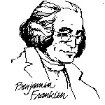
Benjamin Franklin demonstrated that lightning is a form of electricity.

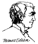
Thomas Edison invented the first commercially viable incandescent light bulb.

Nikola Tesla pioneered the use of alternating current (AC), which enabled the efficient transmission of electricity over long distances. He also experimented with wireless electricity.

Curious why Tesla’s ideas beat Edison’s? Our article on alternating current breaks down the advantages of alternating current (AC) over direct current (DC).

Before Tesla’s innovations, arc lighting used direct current (DC) but was limited to outdoor and short-range applications. His work made it possible for electricity to be transmitted to homes and factories, revolutionizing lighting and industry.


Understanding Electric Charge and Current

Electricity is the movement of electrically charged particles, typically electrons. These particles can move either statically, as in a buildup of charge, or dynamically, as in a flowing current.

All matter is made of atoms, and each atom consists of a nucleus with positively charged protons and neutral neutrons, surrounded by negatively charged electrons. Usually, the number of protons and electrons is balanced. But when that balance is disturbed—when electrons are gained or lost—an electric current is formed as those electrons move.

For a step-by-step walkthrough of everything from circuits to safety, visit how electricity works.


Electricity as a Secondary Energy Source

Electricity doesn’t occur naturally in a usable form. It must be generated by converting other types of energy. In fact, electricity is a manufactured product. That’s why electricity is called a secondary energy source—it carries energy from its original form to where we need it.

We generate electricity by transforming mechanical energy—such as spinning a turbine—into electrical energy. This conversion happens at power plants that use a variety of fuels and methods:

  • Fossil fuels (coal, oil, natural gas)

  • Nuclear energy

  • Renewable sources like wind, solar, and hydroelectric

If turbines, magnets, and power plants intrigue you, see how electricity is generated for a deeper dive.


How Electricity Was Brought Into Homes

Before electricity generation began on a mass scale, cities often developed near waterfalls, where water wheels powered mills and machines. The leap from mechanical energy to electrical energy enabled power to travel not just across a town, but across entire countries.

Beginning with Franklin’s experiments and followed by Edison’s breakthrough with indoor electric light, the practical uses of electricity expanded rapidly. Tesla’s AC power system made widespread electric distribution feasible, bringing light, heat, and industry to homes and cities worldwide.


How Transformers Changed Everything

To transmit electricity efficiently over long distances, George Westinghouse developed the transformer. This device adjusts the voltage of electrical power to match its purpose—high for long-range travel, low for safe use in homes.

Transformers made it possible to supply electricity to homes and businesses far from power plants. The electric grid became a coordinated system of generation, transmission, distribution, and regulation.

Even today, most of us rarely consider the complexity behind our wall sockets. But behind every outlet lies a vast infrastructure keeping electricity flowing safely and reliably.


How Is Electricity Generated?

Electric generators convert mechanical energy into electricity using the principles of magnetism. When a conductor—such as a coil of wire—moves through a magnetic field, an electric current is induced.

In large power stations, turbines spin magnets inside massive generators. These turbines are driven by steam, water, or wind. The rotating magnet induces small currents in the coils of wire, which combine into a single continuous flow of electric power.

Discover the principle that turns motion into power in electromagnetic induction, the heart of every modern generator.


Measuring Electricity

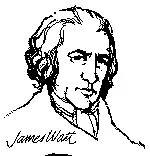
Electricity is measured in precise units. The amount of power being used or generated is expressed in watts (W), named after inventor James Watt.

  • One watt is a small unit of power; 1,000 watts equal one kilowatt (kW).

  • Energy use over time is measured in kilowatt-hours (kWh).

  • A 100-watt bulb burning for 10 hours uses 1 kWh of electricity.

These units are what you see on your electric bill. They represent how much electricity you’ve consumed over time—and how much you’ll pay.

When it’s time to decode your energy bill, the chart in electrical units makes watts, volts, and amps clear.


Related Articles


Related News

Types of Capacitors

The types of capacitors vary by design and application, including ceramic, electrolytic, film, and supercapacitors. Each offers unique benefits for electronics, power supply circuits, energy storage, and filtering needs.


What are the types of capacitors?

The types of capacitors are classified by material, function, and performance, serving vital roles in electronics and electrical systems.

✅ Ceramic, electrolytic, film, and supercapacitors used in diverse applications

✅ Store and regulate electrical energy in circuits, power systems, and devices

✅ Enable filtering, smoothing, and energy storage for stable performance


There are various types of capacitors. They are electronic components of electric filters and tuned circuits that store and release electrical energy. They consist of two conductive plates separated by a dielectric material. When a voltage is applied across the plates, an electric field is created between them, and an electrical charge accumulates on the plates. It represents the distance between the plates. The capacitance of a polarized capacitor is a measure of its ability to store electrical charge. To fully understand how capacitance works in different circuits, it is essential to study the various types and their dielectric materials.

These are widely used in electronic circuits, performing various functions such as filtering, smoothing, coupling, and timing. They can be found in everything from simple electronic devices like flashlights and radios to complex systems such as computers and spacecraft. A solid foundation in basic electricity helps explain why capacitors store and release energy depending on voltage and plate separation.

They come in many different types and sizes, each with unique properties that make them suitable for other applications. The most common types include ceramic, electrolytic, tantalum, film, and supercapacitors.

Engineers often compare capacitance in parallel with capacitance in series to determine how different capacitor arrangements affect circuit behavior.


Schematic symbols for a fixed and variable capacitor.


Ceramic

Ceramic capacitors use ceramic as their dielectric material and are ideal for high-frequency applications. They are available in different types, such as class 1 and class 2. Class 1 caps are used in circuits that require high precision and stability, while class 2 types of capacitors are used in circuits that require high capacitance values. In addition, ceramic caps are commonly used in decoupling, bypassing, and coupling applications.


Electrolytic

Electrolytic caps use an electrolyte as their dielectric material and are polarized. They are known for their high capacitance values and are commonly used in power supply circuits. There are two types of electrolytic caps: aluminum electrolytic caps and tantalum electrolytic caps. Aluminum electrolytic types of capacitors are inexpensive and have a high capacitance value, while tantalum electrolytic caps have higher stability and lower leakage current. Electrolytic caps are commonly used in DC blocking, coupling, and filtering applications.


Film

Film capacitors use a thin plastic or polymer layer as their dielectric material. They are known for their high stability and low losses, which are ideal for high-frequency applications. Film caps come in different types, such as metalized and film/foil, each with unique characteristics. Metalized film caps are used in circuits that require high capacitance values, while film/foil caps are used in circuits that require high precision and stability. Film caps are commonly used in decoupling, coupling, and filtering applications.


Tantalum

Tantalum capacitors are polarized caps that use tantalum metal as their anode. They are known for their high stability and are commonly used in low-voltage applications. Tantalum caps are available in tantalum foil caps and tantalum polymer caps. Tantalum foil caps are known for their high reliability. They are commonly used in aerospace and military applications, while tantalum polymer caps are known for their high capacitance values and low ESR, making them ideal for portable devices.


Mica

Silver mica capacitors use mica as their dielectric material and are known for their high precision, low losses, and excellent stability. They are used in various RF circuits, filters, and timing applications. Mica caps are available in different types, such as silver mica caps and ceramic mica caps. Silver mica caps are known for their high precision and stability. They are commonly used in RF circuits, while ceramic mica caps are known for their high capacitance values and low cost.


Oil


Variable Types

Variable caps are used in electronic circuits where the capacitance value needs to be adjusted. They consist of two conductive plates separated by an air gap, and the capacitance value can be changed by adjusting the distance between the plates. For example, variable caps are commonly used in radio tuning circuits and frequency control circuits.


Supercapacitors

Supercapacitors, also known as ultracapacitors, are a type of capacitor that has a higher energy storage capacity than other types. They are commonly used in applications where high power delivery is needed, such as in electric vehicles and renewable energy systems. They have a higher energy density than electrolytic caps and can be charged and discharged quickly, making them ideal for applications with a quick power boost.


Paper

Paper caps use paper as their dielectric material and are known for their high stability and low losses. Therefore, they are commonly used in filters, timing, and coupling applications. Paper caps are available in different types, such as oil-impregnated paper caps and metalized paper caps. Oil-impregnated paper caps are known for their high stability. Therefore, they are commonly used in high-voltage applications, while metalized paper caps are known for their high capacitance values and low cost.


Power

Power capacitors like power electronics and motor drives are designed for high voltage and high current applications. They are available in different types, such as film and electrolytic, each with unique characteristics. Power caps are known for their high reliability and low losses, making them ideal for high-power applications.


Frequently Asked Questions


What is an electrolytic capacitor, and how is it used?

An electrolytic capacitor is a type of capacitor that uses an electrolyte to achieve a more considerable capacitance value than other types. They are commonly used in power supply circuits due to their high capacitance values and ability to handle high voltages. Electrolytic caps have a polarized design and need to be installed with the correct polarity. Otherwise, they can fail or even explode due to the working voltage ratings. The unit of capacitance, measured in farads, is explained in more detail on our unit of capacitance page, along with practical examples. When comparing passive components, it is helpful to explore both the types of resistors and the types of caps to see how they complement each other in circuits.


How do ceramic capacitors differ?

Ceramic capacitors are a type of capacitor that uses a ceramic material as the dielectric. They are known for their high stability, low cost, and low leakage current. They can also operate at high temperatures due to their insulating layer.

What is a tantalum capacitor, and what are its advantages and disadvantages?

A tantalum capacitor is an electrolytic capacitor that uses tantalum as the anode material. They have a high capacitance per volume ratio and are commonly used in electronic circuits where space is limited. Tantalum ones also have a high level of stability and low leakage current. Additionally, they can operate at high temperatures due to the oxidized layer on the surface. However, they are more expensive than other types and can be sensitive to voltage spikes, which can cause them to fail.


What are film capacitors, and how are they used in electronic circuits?

Film capacitors are a type of capacitor that uses a thin film as the dielectric. They are known for their stability, low leakage current, and ability to operate at high frequencies. Film caps are commonly used in high-precision electronic circuits, such as audio equipment and signal processing circuits. The distance between the plates in a film capacitor represents the capacitance value.


What are the advantages and disadvantages of using supercapacitors?

Supercapacitors, also known as ultra, are a type of capacitor that has a much higher capacitance value than other types. As a result, they can store and release energy quickly and can handle many charge and discharge cycles. Additionally, they can operate at high temperatures. However, supercapacitors have a lower energy density than other types of energy storage devices, such as batteries, and can be more expensive due to their large capacitance.


How do variable capacitors differ from fixed capacitors?

Variable capacitors have a capacitance value that can be adjusted. They have commonly used in radio frequency (RF) circuits where the capacitance must be tuned to a specific frequency. Unlike fixed ones, variable ones have a moving plate that can be adjusted to change the capacitance value. They can also operate at high temperatures due to their insulating layer.


Related Articles


View more

What is Current Electricity?

Current electricity is the flow of electric charge through a conductor, usually as moving electrons. It powers devices in homes and industries. Driven by voltage, this flow enables the transfer of energy through wires, forming the basis of modern electrical systems.


What is Current Electricity?

Current electricity refers to the continuous movement of electric charges (typically electrons) through a conductor, driven by an electromotive force (EMF), or voltage.

✅ Describes the movement of electric charge through a conductor

✅ Powers electrical devices in homes, industries, and electronics

✅ Exists as direct current (DC) or alternating current (AC)

Current is defined as an electrical charge in motion. It consists of a flow of negatively charged electrons from atom to atom through a conductor in an electrical circuit. The external force that causes the electron current flow of electric charge is called the electromotive force (emf) or voltage.

When charges move through these wires, they generate different forms of energy, which can power devices and systems. One common type of current is alternating current (AC), where the direction of the charge flow periodically reverses. This movement of charges can be compared to water flowing through a pipe, where the electrical potential pushes the flow, making it essential for transporting energy efficiently across distances.


The Quantitative Definition

Electric current is defined as the rate of flow of electric charge:

I = Q / t

Where:

  • I is current in amperes (A)

  • Q is charge in coulombs (C)

  • t is time in seconds (s)

For example, a current of 1 ampere means 1 coulomb of charge flows per second through a given point in the circuit.


Types of Current: AC and DC

  • Direct Current (DC): Charge flows in one constant direction. Example: Batteries.

  • Alternating Current (AC): Charge reverses direction periodically. Example: Household wall outlets (typically 60 Hz in North America).


How Current Electricity Works

Electric current arises when free electrons move through a conductor. In metals, these electrons are loosely bound and can drift when a voltage is applied. This movement is like water flowing through a pipe — voltage acts as the pressure that pushes the electrons along.

Voltage sources such as batteries or generators create this pressure, known as electromotive force (emf). The electrons flow from the negative terminal (excess electrons) toward the positive terminal (electron deficiency).


Effects of Electric Current

Electric current produces multiple observable effects:

  • Magnetic effect: Current creates magnetic fields (used in motors and transformers).

  • Thermal effect: Electric current generates heat (used in heaters and toasters).

  • Chemical effect: In electrolysis, current causes chemical reactions.

These effects make current electricity essential for thousands of real-world applications.


Ohm’s Law and Resistance

Ohm’s Law defines the relationship between voltage (V), current (I), and resistance (R):

V = I × R

Where:

  • V is voltage in volts

  • I is current in amperes

  • R is resistance in ohms (Ω)

This relationship helps calculate circuit behavior and select the right components for safe and effective electrical design.


Measuring Current

Current is measured using devices such as:

  • Ammeter: Installed in series with a circuit to measure current directly.

  • Clamp meter: Measures current without disconnecting wires, using magnetic field sensing.

  • Multimeter: A general-purpose tool that can measure voltage, resistance, and current.


Real-World Applications

Current electricity is present in virtually every aspect of modern life:

  • Lighting systems

  • Household appliances

  • Industrial machinery

  • Electric vehicles

  • Cell phones and computers

  • Medical equipment

  • Power grids and transmission lines

It also flows in biological systems, such as ion currents in nerve cells and plasma currents in scientific and industrial applications.


Static vs. Current Electricity

Although both involve electric charges, static electricity refers to charges at rest, whereas current electricity refers to the motion of those charges. Static electricity may build up and discharge suddenly, but only current electricity performs continuous work, such as powering a device or generating heat.


Frequently Asked Questions


What is an example?

Examples of current electricity are starting a car, turning on a light, cooking on an electric stove, watching TV, shaving with an electric razor, playing video games, using a phone, charging a cell phone and more. 


Is current and electricity the same?

Current is a general characteristic of alternating current AC, like voltage and resistance. It's a name given to the flow of electrons (charge) through a medium. Electricity is a generic term used to describe the common flow of energy that powers all electrical devices. Current, in general, refers to any flow.


What are the two types of current electricity?

There are two different types of current in widespread use today. They are direct current, abbreviated DC, and alternating current, which is abbreviated AC. In a direct current, the electrons flow in one direction.

The electromotive force (emf) or voltage, as explained by Ohm's law, is created by a battery that consists of one positively charged and one negatively charged terminal. The negative terminal has an excess of electrons, while the positive terminal has a deficiency of electrons. When a conductor, in this case an electric light bulb, is connected to the two terminals of the battery, a flow of electrons occurs, producing both magnetic fields and an electric field. The positive terminal of the battery has a shortage of electrons and thus attracts electrons from the conductor. The negative terminal has an excess of free electrons to move, which repels electrons into the conductor.

Although "static" and "current" may seem different, they are really the same—both consist of electrical charges. Static electricity consists of electrons at rest on an insulated object and does little work. CE charge flows and does useful work. When static electricity is discharged, it is no longer static electricity — it is actually current electricity.

CE may also be classified as either direct current (DC) or alternating current (AC) based on the voltage source. Direct current voltage produces a constant flow of electrons in one direction only. Alternating current voltage produces a flow of positive and negative charge electrons in both directions, with varying magnitude. A battery is a common DC voltage source, while an electrical wall outlet is the most common AC voltage source (Figure 1).

Polarity identification (+ or -) and magnetic fields are one way to distinguish between a voltage source and a current source. Polarity can be identified on direct current circuits, but in alternating current circuits, the current continuously reverses direction; therefore, polarity cannot be identified. Additionally, it is essential to determine whether an electrical energy source generates alternating current or direct current. Many control and load components are designed to operate with a specific type of current. Operating the components with the wrong type of current or DC polarity can result in improper operation and/or permanent damage to the component.


Fig. 1. Current Electricity. Electrical charges moves.


Related Articles


View more

What is Energy?

Energy is the capacity to do work, powering motion, heat, and electricity. It exists in many forms—kinetic, potential, chemical, thermal, and renewable—transforming constantly to sustain life, industry, and the universe itself.


What is Energy?

Energy is a fundamental concept in physics that describes the capacity of a physical system to perform work. In a sense, energy is the ability to do work.

✅ Exists in forms like kinetic, potential, thermal, chemical, and electrical

✅ Transforms between forms but is conserved under physical laws

✅ Powers human activity, industry, and natural processes


To fully understand what energy is, it helps to start with Basic Electricity, which explains the foundation of how electrical systems operate in daily life.

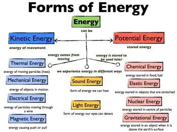
It can be created or released through chemical reactions, nuclear reactions, and electromagnetic waves. Energy is classified into various types based on its origin, nature, and form, including mechanical, thermal, chemical, electrical, radiant, gravitational, nuclear, and sound. With the rise of technology and the global population, energy use has surged, intensifying the demand for alternative and renewable energy sources such as solar, wind, hydropower, and geothermal. 


History and Conceptual Origins

The word "energy" comes from the Greek "energeia," meaning activity or operation. Ancient philosophers, such as Aristotle, used it to describe vitality and action. In the 17th to 19th centuries, scientists such as Newton, Joule, and Helmholtz formalized energy as a measurable quantity in mechanics and thermodynamics. By the 20th century, Einstein’s equation E = mc² had shown that mass itself is a form of energy, reshaping physics and cosmology.


The Law of Conservation of Energy

The law of conservation of energy states that the total amount of energy in a closed system remains constant. Energy cannot be created or destroyed; it can only change form. Whether in chemical reactions, mechanical systems, or nuclear processes, the initial and final total energy always balances.

Energy is typically measured in joules (J). One joule equals the work done when a force of one newton moves an object one meter. Larger quantities are measured in kilojoules (kJ) or kilowatt-hours (kWh), which are commonly used in electricity billing.


The Mathematics of Energy

Energy is quantified with precise formulas:

    • Kinetic energy: KE = ½ mv²

    • Potential energy: PE = mgh

    • Work: W = F × d

These equations demonstrate how motion, position, and force are translated into measurable energy. The joule is equivalent to newton × meter, tying energy directly to mechanics.


What is Energy Transformation and Efficiency

Energy transformations follow the principles of thermodynamics, where no process is perfectly efficient. For example, in an engine, the conversion of chemical fuel into mechanical work produces useful power, but some energy is always lost as heat. These limitations underscore the importance of studying energy efficiency in both engineering and environmental science.

In real systems, energy constantly transforms:

  • Combustion in engines: chemical → thermal → mechanical → electrical

  • Solar panels: radiant → electrical

  • Hydropower: gravitational potential → kinetic → electrical

Yet no process is perfectly efficient. Friction, resistance, and heat losses dissipate useful energy, echoing the second law of thermodynamics and the concept of entropy. This inefficiency shapes the design of power plants, engines, and renewable systems. 


Different Types of Energy?

Energy can be classified into various types based on origin, nature, and form. Each type has unique characteristics, examples, and applications in everyday life and industry.

Mechanical Energy

Mechanical energy is the energy of motion or position. It includes:

  • Potential energy – stored energy due to position or configuration (e.g., water behind a dam).

  • Kinetic energy – energy of motion (e.g., a moving car).
    Mechanical energy is widely used in engines, turbines, and machines.


Thermal Energy

Thermal energy is related to the temperature of an object or system, arising from the kinetic motion of its atoms and molecules. It transfers between objects as heat. Everyday examples include boiling water, heating systems, and combustion engines.


Chemical Energy

Chemical energy is stored in the bonds of molecules and released during chemical reactions. Examples include gasoline fueling a car, food fueling our bodies, and batteries powering electronics. It underpins most biological and industrial processes.


Electrical Energy

Electrical energy results from the movement of electrons through a conductor. It powers lighting, electronics, appliances, and the global power grid. It is easily transported and converted into other forms of energy. Since energy drives current flow, learning about Electrical Energy and how it relates to Voltage and Current makes the concept more practical.


Radiant Energy

Radiant energy is carried by electromagnetic waves, including visible light, radio waves, and microwaves. It enables vision, communication systems, and solar power technology. Sunlight is the most significant source of radiant energy on Earth.


Gravitational Potential Energy

Gravitational energy is stored by objects in a gravitational field due to their height or mass. Lifting an object, climbing a hill, or operating a hydroelectric dam all rely on gravitational potential energy.


Nuclear Energy

Nuclear energy is released during atomic reactions, such as fission (splitting nuclei) or fusion (combining nuclei). It is harnessed in nuclear power plants to generate electricity and powers stars through fusion.


Sound Energy

Sound energy comes from the vibrations of particles in a medium such as air, water, or solids. It is essential in communication, music, sonar, and countless daily experiences.


Comparison Table of Energy Forms

Form Definition Example Common Use / Efficiency
Mechanical Motion or position (kinetic + potential) Car in motion, dam reservoir Engines, machines, turbines
Thermal Motion of atoms/molecules, heat transfer Boiling water Heating, engines
Chemical Energy in molecular bonds Gasoline, food, batteries Fuels, metabolism, storage
Electrical Electron flow through conductors Light bulb, power lines Appliances, power systems
Radiant Electromagnetic waves Sunlight, radio waves Solar panels, communications
Gravitational Position in a gravitational field Falling rock, hydro dam Hydropower, lifting systems
Nuclear Atomic fission/fusion Nuclear reactor, stars Electricity generation
Sound Vibrations in the medium Music, sonar, speech Communication, entertainment


What is Energy in Everyday Life?

Energy is used in numerous everyday activities, including heating and cooling homes, cooking, transportation, communication, and entertainment. Energy use has increased dramatically with the growth of technology and the global population. However, the availability of energy sources is limited, and the demand is increasing. This has led to a search for alternative and renewable energy sources, such as solar, wind, hydropower, and geothermal energy. The physics of 3 phase electricity and 3 phase power demonstrates how energy is efficiently distributed through modern power grids.

Renewable energy sources, such as solar energy, are gaining popularity due to their clean, sustainable, and renewable nature. Solar energy is derived from the sun's radiation and can be converted into electricity through photovoltaic (PV) cells or concentrated solar power (CSP) systems. Solar energy is utilized for various purposes, including generating electricity, heating water, and drying crops. The relationship between energy, Active Power, and Reactive Power is key to understanding how electricity performs useful work.


What is Energy in Physics?

In physics, the concept of energy is closely tied to thermodynamics, which explains how heat and work are transferred within systems. The law of conservation of energy ensures that energy is never lost, only changed in form through conversion processes. Whether it is the power delivered by an engine, the work performed by a force, or the density of energy stored in fuels and batteries, different forms of energy shape how the physical world operates and how technology supports human progress.

  • Biology: Cells use chemical energy stored in ATP for growth and repair.

  • Physics: Einstein’s equation E = mc² links matter and energy, essential in cosmology and nuclear physics.

  • Engineering: Modern grids rely on energy storage (batteries, pumped hydro), demand response, and smart systems to balance supply and demand.

Energy principles are also explained through fundamental laws, such as Ohm’s Law and Ampere’s Law, which connect voltage, current, and resistance.


Future of Energy

As global demand increases, the future of energy will focus on improving storage systems and raising energy density in fuels and batteries. Advances in renewable systems must also balance the conservation of resources with reliable power delivery. New technologies are being developed to optimize energy conversion and minimize losses, ensuring sustainable solutions for future generations. The future hinges on decarbonization, the integration of renewable energy, and global policy shifts. Fossil fuel limitations and climate change demand innovation in:

  • Large-scale storage (lithium batteries, hydrogen fuel cells).

  • Grid modernization and smart energy management.

  • Sustainable policy frameworks balancing demand with environmental limits.

Energy is not only a scientific concept but also a central issue shaping economies, technology, and our planet’s survival.


How is energy measured and quantified?

Energy is typically measured in joules (J) or kilojoules (kJ). The joule is the unit of measurement for energy in the International System of Units (SI). For example, one joule is the amount of energy needed to move an object with a force of one newton (N) over a distance of one meter (m). Kilojoules (kJ) measure larger amounts of energy, such as the energy content of food or the energy output of power plants.

Energy measurements vary depending on the forms being studied. For instance, thermal systems adhere to the laws of thermodynamics, whereas electrical systems prioritize power output and efficiency. Units like joules, calories, and kilowatt-hours quantify the work done, while energy density helps compare fuels and storage methods in practical applications.

Beyond joules, energy is measured in:

  • Calories – food energy.

  • BTU (British Thermal Unit) – heating and fuel.

  • Kilowatt-hours – electricity billing.

Conversions between units help bridge the gap between physics, engineering, and daily life. For example, a 100-watt light bulb consumes 100 joules every second.


Frequently Asked Questions


What is the difference between energy and power?

Energy is the capacity to do work; power is the rate of energy transfer, measured in watts (joules per second).


Can energy be created?

No. According to the law of conservation, energy cannot be created or destroyed, only transformed.


What is energy density?

Energy density refers to the amount of energy stored per unit mass or volume, which is particularly important in fuels and batteries.


How is energy related to thermodynamics?

The first law describes conservation; the second law explains inefficiencies and entropy.


Related Articles


View more

Define Electromagnetism

Electromagnetism is the branch of physics that studies the interaction between electric currents and magnetic fields. It explains how electricity generates magnetism and powers devices such as motors, generators, and transformers in modern electrical systems.


How Should We Define Electromagnetism?

Here's a good way to define electromagnetism: Electromagnetism is a branch of physics involving the study of the electromagnetic force, a type of physical interaction that occurs between electrically charged particles.

✅ Explains the relationship between electricity and magnetism

✅ Governs the operation of motors, generators, and transformers

✅ Forms the basis for electromagnetic waves like light and radio

The electromagnetic force is carried by electromagnetic fields, which are composed of electric fields and magnetic fields, and it is responsible for electromagnetic radiation, such as light.


Who Discovered Electromagnetism?

In 1820, the Danish physicist, Hans Christian Oersted, discovered that the needle of a compass brought near a current-carrying conductor would be deflected. When the current flow stopped, the compass needle returned to its original position. This important discovery demonstrated a relationship between electricity and magnetism that led to the development of the electromagnet and to many of the inventions on which modern industry is based.

Oersted discovered that the magnetic field had no connection with the conductor in which the electrons were flowing, because the conductor was made of nonmagnetic copper. The electrons moving through the wire created the magnetic field around the conductor. Since a magnetic field accompanies a charged particle, the greater the current flow, the greater the magnetic field. Figure 1 illustrates the magnetic field around a current-carrying wire. A series of concentric circles around the conductor represents the field, which, if all the lines were shown, would appear more as a continuous cylinder of such circles around the conductor.


Fig. 1 - Magnetic field formed around a conductor in which current is flowing.


As long as current flows in the conductor, the lines of force remain around it. [Figure 2] If a small current flows through the conductor, there will be a line of force extending out to circle A. If the current flow is increased, the line of force will increase in size to circle B, and a further increase in current will expand it to circle C. As the original line (circle) of force expands from circle A to B, a new line of force will appear at circle A. As the current flow increases, the number of circles of force increases, expanding the outer circles farther from the surface of the current-carrying conductor.


Fig. 2 - Expansion of magnetic field as current increases.


If the current flow is a steady, nonvarying direct current, the magnetic field remains stationary. When the current stops, the magnetic field collapses, and the magnetism around the conductor disappears.

A compass needle is used to demonstrate the direction of the magnetic field around a current-carrying conductor. Figure 3 View A shows a compass needle positioned at right angles to, and approximately one inch from, a current-carrying conductor. If no current were flowing, the north-seeking end of the compass needle would point toward the Earth’s magnetic pole. When current flows, the needle lines itself up at right angles to a radius drawn from the conductor. Since the compass needle is a small magnet, with lines of force extending from south to north inside the metal, it will turn until the direction of these lines agrees with the direction of the lines of force around the conductor. As the compass needle is moved around the conductor, it will maintain itself in a position at right angles to the conductor, indicating that the magnetic field around a current-carrying conductor is circular. As shown in View B of Figure 3, when the direction of current flow through the conductor is reversed, the compass needle points in the opposite direction, indicating that the magnetic field has reversed its direction.


Fig.3 - Magnetic field around a current-carrying conductor.


A method for determining the direction of the lines of force when the direction of current flow is known is illustrated in Figure 4. If the conductor is grasped in the left hand, with the thumb pointing in the direction of current flow, the fingers will be wrapped around the conductor in the same direction as the lines of the magnetic field. This is called the left-hand rule.


Fig.4 - Left-hand rule.


Although it has been stated that the lines of force have direction, this should not be construed to mean that the lines have motion in a circular direction around the conductor. Although the lines of force tend to act in a clockwise or counterclockwise direction, they are not revolving around the conductor.

Since current flows from negative to positive, many illustrations indicate the current direction with a dot symbol on the end of the conductor when the electrons are flowing toward the observer and a plus sign when the current is flowing away from the observer. [Figure 5]


Fig. 5 - Direction of current flow in a conductor.


When a wire is bent into a loop and an electric current flows through it, the left-hand rule remains valid. [Figure 6]


Fig. 6 - Magnetic field around a looped conductor.


If the wire is coiled into two loops, many of the lines of force become large enough to include both loops. Lines of force go through the loops in the same direction, circle around the outside of the two coils, and come in at the opposite end. [Figure 7]


Fig. 7 - Magnetic field around a conductor with two loops.


When a wire contains many such loops, it is referred to as a coil. The lines of force form a pattern through all the loops, causing a high concentration of flux lines through the center of the coil. [Figure 8]


Fig. 8 - Magnetic field of a coil.


In a coil made from loops of a conductor, many of the lines of force are dissipated between the loops of the coil. By placing a soft iron bar inside the coil, the lines of force will be concentrated in the center of the coil, since soft iron has a greater permeability than air. [Figure 9] This combination of an iron core in a coil of wire loops, or turns, is called an electromagnet, since the poles (ends) of the coil possess the characteristics of a bar magnet.


Fig. 9 - Electromagnet.


The addition of the soft iron core does two things for the current-carrying coil. First, the magnetic flux increases, and second, the flux lines become more concentrated.

When direct current flows through the coil, the core becomes magnetized with the same polarity (north and south poles) as the coil would have without the core. If the current is reversed, the polarity will also be reversed.

The polarity of the electromagnet is determined by the left-hand rule in the same manner as the polarity of the coil without the core was determined. If the coil is grasped in the left hand in such a manner that the fingers curve around the coil in the direction of electron flow (minus to plus), the thumb will point in the direction of the north pole. [Figure 10]


Fig. 10 - Left-hand rule applied to a coil.

The strength of the magnetic field of the electromagnet can be increased by either increasing the flow of current or the number of loops in the wire. Doubling the current flow approximately doubles the strength of the field, and similarly, doubling the number of loops approximately doubles the magnetic field strength. Finally, the type of metal in the core is a factor in the field strength of the electromagnet.

A soft iron bar is attracted to either pole of a permanent magnet and, likewise, is attracted by a current-carrying coil. The lines of force extend through the soft iron, magnetizing it by induction and pulling the iron bar toward the coil. If the bar is free to move, it will be drawn into the coil to a position near the center where the field is strongest. [Figure 10-35]


Fig. 11 - Solenoid with iron core.


Electromagnets are utilized in various electrical instruments, including motors, generators, relays, and other devices. Some electromagnetic devices operate on the principle that an iron core, held away from the center of a coil, will be rapidly pulled into its center position when the coil is energized. This principle is utilized in the solenoid, also known as a solenoid switch or relay, where the iron core is spring-loaded off-center and moves to complete a circuit when the coil is energized. 


Related Articles


View more

Electrical Short Circuit

An electrical short circuit occurs when current takes an unintended path with low resistance, resulting in excessive heat, arc faults, or increased fire risks. Proper circuit protection, insulation, and grounding methods are vital for preventing damage.


What is an Electrical Short Circuit?

An electrical short circuit is an abnormal condition in which electricity bypasses normal wiring paths, causing high current flow and serious hazards.

✅ Results in overheating, arc faults, or fires

✅ Requires protective devices and grounding for safety

✅ Demands inspection, risk assessment, and prevention

This dangerous event can result in power outages, damaged appliances, or even fires. By understanding the types of short circuits, their causes, detection methods, and prevention strategies, we can greatly reduce the risks. When studying short circuits, it is helpful to first understand the principles of basic electricity, as the same laws of voltage, current, and resistance explain why faults occur.


Causes of Short Circuits

There are several reasons why a short circuit may occur. Common causes include faulty appliance wiring, loose wire connections, and damaged insulation on wires. These issues can lead to current flowing through an unintended path, creating a short circuit.

Short circuits happen for many reasons, ranging from everyday wear to unusual accidents:

  • Damaged or faulty wiring – Insulation breakdown from age or overheating.

  • Water or moisture ingress – Flooding, leaks, or humidity can allow current to bypass insulation.

  • Pest damage – Rodents chewing wiring can strip insulation and create direct shorts.

  • Mechanical damage – Nails, drilling, or physical stress on cables.

  • Corrosion in connections – Loose or corroded joints create hot spots and unintended paths.

  • Appliance defects – Internal failures in motors, compressors, or electronics.

  • Ground faults vs. short circuits – A short is current between conductors, while a ground fault involves current leaking to earth.

  • Overload vs. short – Overload is too much current for too long; a short is a sudden surge with very low resistance.


Detection and Symptoms

Detecting a short circuit can be challenging, but some common signs may indicate its presence. Detecting a short circuit can be difficult, but common warning signs include:

  • Frequent tripping of breakers or GFCIs

  • Flickering or dimming lights

  • Buzzing or crackling sounds in outlets

  • Burning smells or discolored outlets

  • Damaged insulation or melted wires

For diagnosis, electricians use multimeters, insulation testers (meggers), clamp meters, and thermal imaging cameras to isolate fault locations. Tracers can also help locate hidden shorts inside walls. In three-phase systems, a fault between conductors can cause even greater hazards, making it essential to understand how three-phase electricity behaves under fault conditions. Ground faults are often confused with shorts, but a true electrical fault may involve multiple types of abnormal current flow.


Theory of a Short Circuit

A short circuit illustrates Ohm’s Law (V = I × R): when resistance (R) drops close to zero, current (I) increases dramatically. This sudden fault current stresses wiring, overheats insulation, and can exceed equipment ratings. That’s why time-current curves, protective relays, and properly sized conductors are crucial for safety. Protective devices are designed to limit current and prevent excessive electrical resistance heating that can trigger a fire.


Prevention

Prevention is key to safety. Prevention is the most effective protection. Strategies include:

  • Installing arc fault circuit interrupters (AFCIs) to detect dangerous arcs.

  • Using fuses, breakers, and GFCIs for fault interruption.

  • Adding surge protectors to handle transient spikes.

  • Ensuring proper conductor sizing and insulation quality.

  • Using protective relays and redundancy in industrial systems.

  • Regular inspections of cords, outlets, and panels.

Modern codes, such as the National Electric Code (NEC), the Canadian Electric Code, and IEC standards, all require specific protection and device ratings to reduce hazards.


Dangers of Short Circuits

Short circuits can pose significant risks to both people and property. They are among the most dangerous faults:

  • Fire hazards – Sparks and overheated wires ignite flammable materials.

  • Electric shock – Fault currents may flow through people during contact.

  • Equipment damage – Motors, appliances, and electronics can be severely damaged or destroyed.

For example, a refrigerator's shorted compressor can ignite nearby insulation, while an industrial panel's short can trip upstream breakers, causing outages and costly downtime. They are one of the many dangers of electricity that electricians must guard against through the use of insulation, grounding, and protective equipment.


How To Repair

If you suspect a short in the power system, it's crucial to address the issue immediately. If you suspect a short:

  1. Shut off the power at the breaker or unplug devices.

  2. Inspect outlets, cords, and panels for visible damage.

  3. Use diagnostic tools to isolate the faulted loop.

  4. Replace damaged wires or devices.

  5. If uncertain, consult a licensed electrician — shorts are not DIY-friendly.


Difference Between a Short Circuit and an Open Circuit

While both short circuits and open circuits involve disruptions in normal functioning, they are fundamentally different. A short occurs when the current flows through an unintended path, resulting in a sudden surge in current. In contrast, an open path is a break in its continuity, which stops the flow of current altogether. Both situations can cause problems in your system and should be addressed promptly.


Frequently Asked Questions


Can a short circuit happen in a GFCI outlet?

Yes. GFCIs protect against ground faults, but not all types of shorts. Breakers and fuses are still required.


How often should wiring be inspected?

Residential wiring should be inspected every 5–10 years, or immediately if signs of overheating or frequent breaker trips are observed.


What is the difference between a ground fault and a short circuit?

A ground fault involves current flowing into earth, while a short occurs between conductors. Both are hazardous.

Understanding shorts — their causes, detection, prevention, and associated risks — is crucial for safeguarding people and property. Regular inspections, proper protection, and adherence to codes all reduce hazards. If you suspect a short, act immediately and contact a qualified electrician.


Related Articles


View more

What is a Potentiometer?

A potentiometer is a variable resistor that adjusts voltage in a circuit. It’s used for controlling electrical devices like volume knobs, sensors, and dimmers. Potentiometers regulate current flow by varying resistance, making them essential in analog electronic applications.


What is a Potentiometer?

A potentiometer is a type of adjustable resistor used to control voltage or current in an electrical circuit.

✅ Adjusts resistance to control voltage in circuits

✅ Commonly used in audio controls and sensors

✅ Essential for analog signal tuning and regulation

At its core, a potentiometer functions as a variable resistor. By moving the wiper (a movable terminal) across a resistive element, the device varies the output voltage. Depending on the position of the wiper, varying amounts of resistance are introduced into the circuit, thereby adjusting the current flow.

When the wiper moves along the resistive track, it adjusts the total resistance in the circuit, which controls the flow of current. To learn more, see our guide on Electrical Resistance.

A potentiometer acts as an adjustable Voltage divider, splitting the input voltage proportionally between two output terminals based on the wiper’s position.

This relationship is governed by Ohm’s Law Formula, which states that voltage equals current multiplied by resistance (V = IR).

As shown in Figure 6-8, the basic construction of a potentiometer includes:

  • A resistive track (usually carbon, cermet, or wire wound)

  • A movable wiper

  • Three terminals (two fixed, one connected to the wiper)

This setup enables the potentiometer to function as both a voltage divider and a simple variable resistor.


Fig. 6-8 Construction geometry of a potentiometer


Types of Potentiometers

Potentiometers come in several forms, each designed for specific applications:

A potentiometer is considered a variable resistor, one of several important types covered in our guide to Types of Resistors.


Rotary Potentiometer

The most common type, rotary potentiometers, adjust resistance through the rotation of a knob. These are frequently found in volume controls, light dimmers, and measuring instruments. The resistive track inside a potentiometer is made from materials that partially conduct electricity, such as carbon or cermet. For more on conductive materials, see Conductor of Electricity.


Figure 6-9 illustrates the typical circuit symbol for a rotary potentiometer.


Linear Potentiometer (Slide Potentiometer)

Instead of rotating, a linear potentiometer, often referred to as a slide potentiometer, adjusts by sliding a control lever. These are widely used in audio mixers and precision instruments where fine, linear adjustments are needed.


Audio Taper Potentiometer

In audio equipment, human hearing sensitivity is non-linear. Audio taper potentiometers adjust resistance logarithmically to provide a natural, smooth volume change that matches human perception.

Note: If you use a linear-taper potentiometer for audio volume control, the sound may seem to jump suddenly instead of increasing smoothly.


Digital Potentiometer

Digital potentiometers, also known as "digipots," are electronically controlled rather than manually adjusted. They find use in automatic tuning circuits, programmable amplifiers, and microcontroller applications.


Rheostat (Variable Resistor)

Although technically a type of potentiometer, a rheostat uses only two terminals: one fixed terminal and the wiper. It is optimized to control current rather than voltage. Rheostats are commonly used in applications like motor speed control and light dimming.


Practical Applications of Potentiometers

Potentiometers are found in a wide range of everyday and industrial applications:

  • Audio Equipment: Volume and tone controls on stereos and guitars

  • Automobiles: Throttle position sensors, dashboard dimmers

  • Industrial Controls: Machinery speed adjustments

  • Consumer Electronics: Game controller joysticks

  • Laboratory Equipment: Calibration and fine adjustments

Potentiometers are versatile components used in both AC and DC electrical systems, from audio controls to automotive sensors.

Their ability to fine-tune voltage and resistance makes them essential in both analog and digital systems.


How to Test a Potentiometer

Testing a potentiometer is straightforward:

  1. Disconnect power to the circuit.

  2. Use a multimeter set to measure resistance (ohms).

  3. Connect the multimeter probes to the outer two terminals to measure total resistance.

  4. Measure between the wiper and one outer terminal; adjust the control and observe the changing resistance.

Consistent, smooth changes confirm proper operation. Jumps or dead spots may indicate a worn or faulty potentiometer.

A potentiometer is a simple but versatile component that provides adjustable control over voltage or resistance in a circuit. Whether used in audio systems, automotive sensors, or industrial machinery, its importance in electronic design and control systems is undeniable.

Understanding the various types and practical applications of potentiometers can help in selecting the appropriate device for a specific task.

For readers seeking a broader understanding of basic electrical principles, visit our overview of Electricity Fundamentals.


Frequently Asked Questions


What is the difference between a potentiometer and a rheostat?

A potentiometer typically acts as a voltage divider with three terminals, while a rheostat uses only two terminals to control current.


Where are potentiometers commonly used?

Potentiometers are used in volume controls, sensors, gaming controllers, industrial equipment, and calibration tools.


How does a potentiometer adjust voltage?

By moving the wiper across the resistive track, a potentiometer divides the input voltage proportionally between the two output terminals, adjusting the output voltage.


Related Articles


View more

Sign Up for Electricity Forum’s Newsletter

Stay informed with our FREE Newsletter — get the latest news, breakthrough technologies, and expert insights, delivered straight to your inbox.

Electricity Today T&D Magazine Subscribe for FREE

Stay informed with the latest T&D policies and technologies.
  • Timely insights from industry experts
  • Practical solutions T&D engineers
  • Free access to every issue

Download the 2025 Electrical Training Catalog

Explore 50+ live, expert-led electrical training courses –

  • Interactive
  • Flexible
  • CEU-cerified