How to Save Electricity?


How to Save Electricity explained

How to save electricity? Improve energy efficiency, switch to LED lighting, manage standby power, use smart thermostats, insulate homes, schedule heavy appliances off-peak, and conduct energy audits to cut power consumption and lower bills.


How to Save Electricity?

Reduce power consumption with LEDs, smart thermostats, insulation, and off-peak usage to lower energy bills.

✅ Upgrade to LED lighting and ENERGY STAR appliances

✅ Program smart thermostats; set HVAC to efficient ranges

✅ Eliminate standby power with advanced power strips


How to Save Electricity is a popular question. It involves energy conservation and lessens real dollars and preserves a public resource. Here are some ways to cut energy costs without compromising your lifestyle too much. For a deeper primer on cutting household consumption, explore this saving electricity guide for actionable steps.


Control heating and cooling costs

In some climates, heating and cooling represent the largest part of household energy use. In many climates, running your air conditioner at 78 instead of 72 will earn 40% of your cooling bill. You don't have to freeze or roast to death in order to use less energy and earn money. In some climates, heating and cooling represent the largest part of household energy use. In many climates, running your air conditioner at 78 instead of 72 will earn 40% of your cooling bill. You don't have to freeze or roast to death in order to use less energy and earn money.In some climates, heating and cooling represent the largest part of household energy use. In many climates, running your air conditioner at 78 instead of 72 will earn 40% of your cooling bill. You don't have to freeze or roast to death in order to use less energy and earn money. Here are a few tips:

Understanding how HVAC loads draw electric power can help you schedule operation during cooler periods for efficiency.

  • How to Save Electricity? Make sure your filters are clean. Check with the manufacturer of your equipment or with your utility company to see if filters on your units need to be cleaned.
  • Don't heat or cool when no one is home. If you are going to be gone for more than a half an hour, you can turn your heating or cooling off or down. Don't turn off the heat in a cold climate because that may result in the pipes breaking.
  • Supplement your main unit with portable units Running a fan can help you use less air conditioning. Using portable heaters when you are asleep or otherwise staying in one room can mean less use of heat if it means that you don't have to use the main unit.
  • Try setting your thermostat to run less frequently Turn your air conditioner up a degree or two or your heater down a degree or two and see if you still can be comfortable.
  • Time your opening and closing of windows and drapes to reduce heading and cooling costs. On cold, sunny days, opening curtains and drapes while leaving windows closed will help you heat your home. Opening the windows on summer nights helps cool your home. Buying storm windows in some climates reduces heating costs.
  • Check for holes in your roof and in your pipes. This can help reduce up to 10 per cent of your heating and cooling costs.

Track your improvements by reading your electricity meter regularly and noting weekday versus weekend patterns.


Get energy saving ideas from your utility company 

Utility companies are among the few businesses who hope that you use less of their product. Most power companies are anxious to postpone construction of new power plants, so they strongly encourage customers to use less power. 
Utility companies offer energy audits, tips, and other help for customers who want to reduce energy consumption. Call your local utility or log onto their website to see what they have to offer. Many utilities explain how electricity cost components like demand and time-of-use rates affect bills.


Other Electricity Saving tips:

  • Consider how to increase your energy efficiency when buying appliances Appliances are labeled with energy usage comparison tables. Look at these figures. Also, you may be able to buy an adapter to make your older appliances more energy efficient.
  • Turn off appliances that no one is using Turning off TV's, lamps, computers, VCR's, ovens, and other appliances that no one is using can reduce electric energy consumption. Even turning them off for short periods can produce noticeable results.
  • See if an alternative energy company is available In California, electrical deregulation is beginning to result in alternative providers of electric power. This is a trend that should increase nationally. See if that option is available to you.
  • Install low-flow heads in your water closets. Also, check your water heater's temperature and set it for 120 degrees. Putting insulation over your water heater and pipes can also help.
  • Wash and dry only full loads of clothing or dishes

Stay aware of regional electricity prices so you can plan high-use activities for lower-cost periods.

You may not make you rich, but it will help you cut down some on your costs and will help prevent blackouts and power shortages in your community.

Are your company's profits being eroded by escalating energy costs? Can you gamble that your energy costs will go down in the future? What are you doing about preparing and protecting your company from spiraling energy costs?

If you operate in competitive markets, review how electricity deregulation shapes supplier choices and contract terms.

Do you have the knowledge of the dynamic market with the right equipment that will make the 'smart decisions' and make an effective difference in your energy consumption and see your energy bill go down?

Facilities with inductive loads can cut charges by improving power factor through correction equipment and better motor controls.


Do you know about the latest technologies that you can implement now?

These questions can be answered by our new Industrial, Commercial & Institutional Energy Efficiency Handbook. This 100+ page book is jammed with practical information on reducing energy consumption, increase Energy efficiency by using modern technologies such as variable frequency drives, high efficiency electrical devices, energy efficient lighting, energy management control systems, metering and management systems, as well as fan, pump and blower efficiency improvements. We will also list Federal, State, utility and Canadian government programs that will reduce your energy consumption and increase your energy efficiency.


Related Articles

Related News

What is Current Electricity?

Current electricity is the flow of electric charge through a conductor, usually as moving electrons. It powers devices in homes and industries. Driven by voltage, this flow enables the transfer of energy through wires, forming the basis of modern electrical systems.


What is Current Electricity?

Current electricity refers to the continuous movement of electric charges (typically electrons) through a conductor, driven by an electromotive force (EMF), or voltage.

✅ Describes the movement of electric charge through a conductor

✅ Powers electrical devices in homes, industries, and electronics

✅ Exists as direct current (DC) or alternating current (AC)

Current is defined as an electrical charge in motion. It consists of a flow of negatively charged electrons from atom to atom through a conductor in an electrical circuit. The external force that causes the electron current flow of electric charge is called the electromotive force (emf) or voltage.

When charges move through these wires, they generate different forms of energy, which can power devices and systems. One common type of current is alternating current (AC), where the direction of the charge flow periodically reverses. This movement of charges can be compared to water flowing through a pipe, where the electrical potential pushes the flow, making it essential for transporting energy efficiently across distances.


The Quantitative Definition

Electric current is defined as the rate of flow of electric charge:

I = Q / t

Where:

  • I is current in amperes (A)

  • Q is charge in coulombs (C)

  • t is time in seconds (s)

For example, a current of 1 ampere means 1 coulomb of charge flows per second through a given point in the circuit.


Types of Current: AC and DC

  • Direct Current (DC): Charge flows in one constant direction. Example: Batteries.

  • Alternating Current (AC): Charge reverses direction periodically. Example: Household wall outlets (typically 60 Hz in North America).


How Current Electricity Works

Electric current arises when free electrons move through a conductor. In metals, these electrons are loosely bound and can drift when a voltage is applied. This movement is like water flowing through a pipe — voltage acts as the pressure that pushes the electrons along.

Voltage sources such as batteries or generators create this pressure, known as electromotive force (emf). The electrons flow from the negative terminal (excess electrons) toward the positive terminal (electron deficiency).


Effects of Electric Current

Electric current produces multiple observable effects:

  • Magnetic effect: Current creates magnetic fields (used in motors and transformers).

  • Thermal effect: Electric current generates heat (used in heaters and toasters).

  • Chemical effect: In electrolysis, current causes chemical reactions.

These effects make current electricity essential for thousands of real-world applications.


Ohm’s Law and Resistance

Ohm’s Law defines the relationship between voltage (V), current (I), and resistance (R):

V = I × R

Where:

  • V is voltage in volts

  • I is current in amperes

  • R is resistance in ohms (Ω)

This relationship helps calculate circuit behavior and select the right components for safe and effective electrical design.


Measuring Current

Current is measured using devices such as:

  • Ammeter: Installed in series with a circuit to measure current directly.

  • Clamp meter: Measures current without disconnecting wires, using magnetic field sensing.

  • Multimeter: A general-purpose tool that can measure voltage, resistance, and current.


Real-World Applications

Current electricity is present in virtually every aspect of modern life:

  • Lighting systems

  • Household appliances

  • Industrial machinery

  • Electric vehicles

  • Cell phones and computers

  • Medical equipment

  • Power grids and transmission lines

It also flows in biological systems, such as ion currents in nerve cells and plasma currents in scientific and industrial applications.


Static vs. Current Electricity

Although both involve electric charges, static electricity refers to charges at rest, whereas current electricity refers to the motion of those charges. Static electricity may build up and discharge suddenly, but only current electricity performs continuous work, such as powering a device or generating heat.


Frequently Asked Questions


What is an example?

Examples of current electricity are starting a car, turning on a light, cooking on an electric stove, watching TV, shaving with an electric razor, playing video games, using a phone, charging a cell phone and more. 


Is current and electricity the same?

Current is a general characteristic of alternating current AC, like voltage and resistance. It's a name given to the flow of electrons (charge) through a medium. Electricity is a generic term used to describe the common flow of energy that powers all electrical devices. Current, in general, refers to any flow.


What are the two types of current electricity?

There are two different types of current in widespread use today. They are direct current, abbreviated DC, and alternating current, which is abbreviated AC. In a direct current, the electrons flow in one direction.

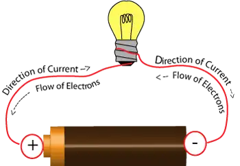
The electromotive force (emf) or voltage, as explained by Ohm's law, is created by a battery that consists of one positively charged and one negatively charged terminal. The negative terminal has an excess of electrons, while the positive terminal has a deficiency of electrons. When a conductor, in this case an electric light bulb, is connected to the two terminals of the battery, a flow of electrons occurs, producing both magnetic fields and an electric field. The positive terminal of the battery has a shortage of electrons and thus attracts electrons from the conductor. The negative terminal has an excess of free electrons to move, which repels electrons into the conductor.

Although "static" and "current" may seem different, they are really the same—both consist of electrical charges. Static electricity consists of electrons at rest on an insulated object and does little work. CE charge flows and does useful work. When static electricity is discharged, it is no longer static electricity — it is actually current electricity.

CE may also be classified as either direct current (DC) or alternating current (AC) based on the voltage source. Direct current voltage produces a constant flow of electrons in one direction only. Alternating current voltage produces a flow of positive and negative charge electrons in both directions, with varying magnitude. A battery is a common DC voltage source, while an electrical wall outlet is the most common AC voltage source (Figure 1).

Polarity identification (+ or -) and magnetic fields are one way to distinguish between a voltage source and a current source. Polarity can be identified on direct current circuits, but in alternating current circuits, the current continuously reverses direction; therefore, polarity cannot be identified. Additionally, it is essential to determine whether an electrical energy source generates alternating current or direct current. Many control and load components are designed to operate with a specific type of current. Operating the components with the wrong type of current or DC polarity can result in improper operation and/or permanent damage to the component.


Fig. 1. Current Electricity. Electrical charges moves.


Related Articles


View more

What is Considered High Voltage? HV Applications Explained

What is considered high voltage? Per IEC/IEEE, voltages above 1 kV AC or 1.5 kV DC; linked to insulation coordination, arc-flash risk, transmission lines, substations, switchgear ratings, clearance/creepage distances, and dielectric breakdown in power systems.


What Is Considered High Voltage?

Voltages above 1 kV AC or 1.5 kV DC are classed as high voltage per IEC/IEEE in power systems.

✅ IEC/IEEE: >1 kV AC or >1.5 kV DC thresholds

✅ Categories: MV, HV, EHV, UHV in power transmission

✅ Impacts insulation, clearance, arc-flash, switchgear ratings


What is Considered High Voltage?

In the world of electrical engineering, understanding voltage levels is crucial. So you might be asked to define high voltage. But what is considered HV? This article explores the definition, classification, and applications of HV and the safety concerns and precautions that come with it. For foundational context, the concept of voltage underpins how these levels are defined and compared across systems.


According to the International Electrotechnical Commission (IEC), HV is typically defined as any voltage above 1000 volts for alternating current (AC) systems and 1500 volts for direct current (DC) systems. However, the term "HV" can also refer to voltages as low as 50 volts in some safety regulations, depending on the context. For example, the US Occupational Safety and Health Administration (OSHA) defines HV as 600 volts or higher in their safety guidelines. Standards often reference nominal voltage values that guide equipment ratings, insulation clearances, and test criteria in practice.

High voltage systems are essential in electric power transmission and distribution, allowing electricity to be transported over long distances with minimal energy loss. Power lines, transmission lines, and transformers all play a role in the power transmission and distribution process. Transformers are used to step up or down voltage levels, depending on whether the electricity is transported over long distances or distributed to end-users. At the point of use, networks step down to low voltage levels suitable for residential and commercial equipment before final delivery.

Voltage classification is a method for organizing voltages based on their range. There are four primary classifications of voltage levels: low (LV), medium  (MV), HV, and extra HV (EHV). Ultra HV (UHV) is another classification for exceptionally high voltages, typically used in long-distance power transmission projects. In distribution grids, medium voltage tiers bridge the gap between long-distance transmission and local feeders in a coordinated hierarchy.

Insulation is a crucial aspect of HV systems, as it prevents electrical current from leaking and causing short circuits, equipment damage, or even fires. Different types of insulation are used depending on the voltage level and application, such as air, gas, oil, or solid materials like plastics and ceramics. For clarity on terminology used in insulation, dielectric strength, and creepage distances, consult common electricity terms that standardize communication across projects.

HV circuits and equipment, such as transformers and switchgear, are designed to handle higher voltages safely and efficiently. These devices are essential components of power distribution networks and are subject to strict design, manufacturing, and testing standards to ensure reliability and safety.

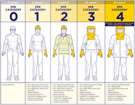
Working with high voltage circuits presents several electrical hazards, such as electric shock, arc flash, and fires. To mitigate these risks, electrical safety measures must be put in place. Workers with HV equipment must follow safety procedures and use appropriate personal protective equipment (PPE), such as insulated gloves, safety glasses, and arc flash suits. Comprehensive electricity safety programs integrate procedures, labeling, lockout/tagout, and training to reduce incident rates.

So, what is considered high voltage? As mentioned earlier, the IEC defines HV as 1000 volts for AC and 1500 volts for DC. However, some safety regulations might consider voltages as low as 50 or 600 volts as HV.

HV is used in power transmission and distribution to transport electricity efficiently over long distances. Transmission lines, transformers, and other equipment are designed to handle HVs and are integral to power distribution networks.

Safety concerns associated with HV systems include electric shock, arc flash, and fires. Proper safety procedures and protective equipment are necessary to minimize these risks. Understanding the broader dangers of electricity helps contextualize HV-specific risks and informs mitigation strategies.

Transformers handle HV levels by stepping up or stepping down the voltage, allowing for efficient power transmission and distribution. They are designed to withstand HV stresses and are subject to rigorous testing and standards.

Various types of insulation are needed for HV applications, including air, gas, oil, and solid materials like plastics and ceramics. The choice of insulation depends on the level and specific application requirements.

The different classifications of voltage levels include low, medium, HV, extra HV, and ultra HV. These classifications help categorize voltage ranges for various applications and safety standards.

When working with HV equipment, workers should follow safety procedures, use appropriate personal protective equipment, and undergo regular training to stay updated on best practices and safety guidelines.

In conclusion, understanding what is considered HV is crucial for electrical systems' safe and efficient operation. HV plays a vital role in power transmission and distribution, allowing electricity to be transported over long distances with minimal losses. Proper insulation, transformers, and other equipment are designed to handle HV levels and ensure the reliability of the electrical infrastructure. Safety concerns associated with HV systems must be addressed through stringent safety procedures, protective equipment, and worker training. We can maintain a safe and efficient electrical infrastructure by adhering to these guidelines and understanding the importance of classifications.


High, Extra-High and Ultra-HV Classifications

High, extra-high, and ultra-high voltage classifications are categories used to define the levels within electrical systems, particularly in power transmission and distribution networks. These classifications help standardize the design, manufacturing, and operation of electrical equipment and ensure safety and efficiency.


High Voltage (HV):

HV is typically defined as levels between 1000 volts (1 kV) and 100,000 volts (100 kV) for alternating current (AC) systems and between 1500 volts (1.5 kV) and 100,000 volts (100 kV) for direct current (DC) systems. HV systems are commonly used in electric power transmission and distribution networks, substations, and industrial facilities. HV allows for efficient power transmission over long distances while reducing energy loss due to resistance.


Extra-High Voltage (EHV):

Extra-high voltage refers to levels above 100,000 volts (100 kV) and up to 300,000 volts (300 kV) for AC systems and between 100,000 volts (100 kV) and 800,000 volts (800 kV) for DC systems. EHV systems are primarily used for long-distance power transmission, where higher levels reduce energy losses even further. EHV lines and equipment require specialized design, manufacturing, and maintenance to ensure safety, reliability, and efficiency. The use of extra-high voltage is also associated with more stringent safety protocols and larger right-of-way requirements for transmission lines.


Ultra-High Voltage (UHV):

Ultra-high voltage classification is designated for levels above 300,000 volts (300 kV) for AC systems and above 800,000 volts (800 kV) for DC systems. UHV systems are used in large-scale power transmission projects that aim to transmit massive amounts of electricity over very long distances with minimal losses. These projects typically connect major power generation sources, such as hydroelectric or nuclear plants, to far-off load centers or densely populated urban areas. As a result, UHV systems demand the highest level of engineering expertise, rigorous testing, and specialized equipment to ensure their safe and efficient operation.


Related Articles

View more

What is a Ground Fault? Hazard Explained

A ground fault occurs when electrical current unintentionally flows to the ground, often through a person or conductive surface. It poses serious shock and fire hazards and typically results from damaged wiring, insulation failure, or water intrusion in electrical systems.


What is a Ground Fault?

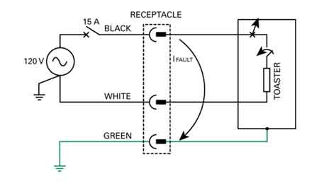
A ground fault is a potentially hazardous electrical event when an unintended electrical path forms between a live electrical conductor and a grounded surface.

✅ Occurs when electrical current flows to ground through an unintended path

✅ Commonly caused by damaged wires, insulation failure, or moisture

✅ Increases the risk of electrical shock and equipment failure

The flow of current through this unintended path, also known as earth leakage, can cause serious electrical shock hazards and damage to electrical systems. Let's examine the causes, dangers, and preventive measures associated with ground faults. Proper electrical grounding is essential to prevent ground faults, as it ensures that stray currents are safely diverted into the earth. 

There are common causes of ground faults. A ground fault occurs because of several factors, including damaged insulation, incorrect wiring, or moisture in the electrical system. Damaged insulation, for example, can expose the conductor of electricity, allowing it to come into contact with a grounded surface. Additionally, moisture can create a conductive path between live conductors and the earth, thereby increasing the risk. Moisture intrusion and damaged insulation can cause faults similar to arc faults, which are discussed further in our power quality troubleshooting resource.

One of the primary dangers associated with ground faults is the risk of electrical shock. When one occurs, it can create a path to the earth through a person, leading to serious injury or even death. Additionally, they can cause overheating, sparking, and fires in electrical systems, posing a significant risk to property and life.

Ground fault circuit interrupters (GFCIs) are essential devices designed to mitigate the risks associated with ground faults. GFCIs constantly monitor the flow of electrical current between the hot wire and the neutral wire. If an imbalance is detected, the GFCI quickly cuts power to the electrical circuit, preventing electrical shock and minimizing potential damage. GFCI outlets are commonly installed in areas where water is present, such as kitchens, bathrooms, and outdoor spaces, as these locations have a higher risk of ground faults. A grounding system should be regularly inspected to minimize the risk of fire and shock caused by unintentional current paths.


Preventing Ground Faults

Preventing and minimizing ground faults involves several steps. First, proper electrical grounding is critical in reducing the risk. A grounding wire connected to the electrical box creates a path for fault current to flow safely to the earth, reducing the likelihood of electrical shock. Regular inspection and maintenance of electrical systems can also help identify potential issues, such as damaged insulation or incorrect wiring, before they lead to ground faults. Additionally, using GFCI-protected outlets and circuit breakers in high-risk areas can help prevent ground faults and protect against shock hazards.

Understanding the differences between ground faults, short circuits, and arc faults is important, as they are all distinct electrical events with unique risks and causes. A short circuit occurs when a live conductor comes into contact with a neutral or grounded conductor, resulting in a sudden surge of current. This can lead to overheating, fires, or damage to electrical equipment. On the other hand, arc faults occur when an electrical arc forms between conductors, often due to damaged or frayed wiring. Arc faults can generate excessive heat and pose a fire risk.

Identifying one in an electrical system can be accomplished through visual inspection, testing, or the use of specialized equipment. For example, signs of a ground fault may include tripped GFCI outlets or circuit breakers, flickering lights, or a burning smell near electrical equipment. Additionally, testing outlets with a ground fault circuit interrupter tester or a multimeter can help determine if a ground fault is present.

Grounding is crucial in preventing ground faults and protecting against electrical shock. By providing a safe path for fault current to flow, earthing helps minimize the risk of injury and damage to electrical systems. Proper earthing involves connecting all electrical equipment, including outlets, switches, and metal boxes, to a grounding wire connected to the earth. This connection helps ensure that unintended electrical paths, such as those caused by ground faults, are safely grounded.


Understanding Ground Faults

Understanding what a ground fault is and how to prevent it is essential for ensuring electrical safety in residential and commercial settings. Proper earthing, regular inspection and maintenance of electrical systems, and the use of GFCI-protected outlets and circuit breakers are all crucial measures in reducing the risk of electrical hazards. By being aware of the dangers associated with ground faults and taking proactive steps to address them, we can help protect our homes, businesses, and loved ones from electrical hazards.

In addition to the precautions mentioned above, it's essential to exercise caution when using power tools and appliances. Many incidents occur when using power tools in damp environments. Always ensure that power tools are in good working condition, with no frayed cords or damaged insulation. Use GFCI-protected outlets or extension cords when operating them in potentially hazardous conditions.

Moreover, educating yourself and those around you about electrical safety is crucial. Understanding the risks associated with ground faults and knowing how to respond in an electrical emergency can save lives. Regularly reviewing safety procedures and ensuring that everyone in your home or workplace knows how to use GFCI outlets and reset buttons. Circuit breakers can significantly reduce the risk of injury or property damage.

Finally, don't hesitate to consult a licensed electrician if you suspect or encounter any electrical issues. Professional electricians have the knowledge and tools to diagnose and repair electrical problems safely and effectively. Attempting to resolve electrical issues without proper training can be dangerous and may lead to further complications.

By adopting a comprehensive approach to electrical safety, we can minimize risks and create a safer environment for ourselves and our communities. Awareness, preventive measures, and education are crucial in reducing the incidence of injuries and ensuring the well-being of everyone interacting with electrical systems.


Related Articles


View more

Types of Capacitors

The types of capacitors vary by design and application, including ceramic, electrolytic, film, and supercapacitors. Each offers unique benefits for electronics, power supply circuits, energy storage, and filtering needs.


What are the types of capacitors?

The types of capacitors are classified by material, function, and performance, serving vital roles in electronics and electrical systems.

✅ Ceramic, electrolytic, film, and supercapacitors used in diverse applications

✅ Store and regulate electrical energy in circuits, power systems, and devices

✅ Enable filtering, smoothing, and energy storage for stable performance


There are various types of capacitors. They are electronic components of electric filters and tuned circuits that store and release electrical energy. They consist of two conductive plates separated by a dielectric material. When a voltage is applied across the plates, an electric field is created between them, and an electrical charge accumulates on the plates. It represents the distance between the plates. The capacitance of a polarized capacitor is a measure of its ability to store electrical charge. To fully understand how capacitance works in different circuits, it is essential to study the various types and their dielectric materials.

These are widely used in electronic circuits, performing various functions such as filtering, smoothing, coupling, and timing. They can be found in everything from simple electronic devices like flashlights and radios to complex systems such as computers and spacecraft. A solid foundation in basic electricity helps explain why capacitors store and release energy depending on voltage and plate separation.

They come in many different types and sizes, each with unique properties that make them suitable for other applications. The most common types include ceramic, electrolytic, tantalum, film, and supercapacitors.

Engineers often compare capacitance in parallel with capacitance in series to determine how different capacitor arrangements affect circuit behavior.


Schematic symbols for a fixed and variable capacitor.


Ceramic

Ceramic capacitors use ceramic as their dielectric material and are ideal for high-frequency applications. They are available in different types, such as class 1 and class 2. Class 1 caps are used in circuits that require high precision and stability, while class 2 types of capacitors are used in circuits that require high capacitance values. In addition, ceramic caps are commonly used in decoupling, bypassing, and coupling applications.


Electrolytic

Electrolytic caps use an electrolyte as their dielectric material and are polarized. They are known for their high capacitance values and are commonly used in power supply circuits. There are two types of electrolytic caps: aluminum electrolytic caps and tantalum electrolytic caps. Aluminum electrolytic types of capacitors are inexpensive and have a high capacitance value, while tantalum electrolytic caps have higher stability and lower leakage current. Electrolytic caps are commonly used in DC blocking, coupling, and filtering applications.


Film

Film capacitors use a thin plastic or polymer layer as their dielectric material. They are known for their high stability and low losses, which are ideal for high-frequency applications. Film caps come in different types, such as metalized and film/foil, each with unique characteristics. Metalized film caps are used in circuits that require high capacitance values, while film/foil caps are used in circuits that require high precision and stability. Film caps are commonly used in decoupling, coupling, and filtering applications.


Tantalum

Tantalum capacitors are polarized caps that use tantalum metal as their anode. They are known for their high stability and are commonly used in low-voltage applications. Tantalum caps are available in tantalum foil caps and tantalum polymer caps. Tantalum foil caps are known for their high reliability. They are commonly used in aerospace and military applications, while tantalum polymer caps are known for their high capacitance values and low ESR, making them ideal for portable devices.


Mica

Silver mica capacitors use mica as their dielectric material and are known for their high precision, low losses, and excellent stability. They are used in various RF circuits, filters, and timing applications. Mica caps are available in different types, such as silver mica caps and ceramic mica caps. Silver mica caps are known for their high precision and stability. They are commonly used in RF circuits, while ceramic mica caps are known for their high capacitance values and low cost.


Oil


Variable Types

Variable caps are used in electronic circuits where the capacitance value needs to be adjusted. They consist of two conductive plates separated by an air gap, and the capacitance value can be changed by adjusting the distance between the plates. For example, variable caps are commonly used in radio tuning circuits and frequency control circuits.


Supercapacitors

Supercapacitors, also known as ultracapacitors, are a type of capacitor that has a higher energy storage capacity than other types. They are commonly used in applications where high power delivery is needed, such as in electric vehicles and renewable energy systems. They have a higher energy density than electrolytic caps and can be charged and discharged quickly, making them ideal for applications with a quick power boost.


Paper

Paper caps use paper as their dielectric material and are known for their high stability and low losses. Therefore, they are commonly used in filters, timing, and coupling applications. Paper caps are available in different types, such as oil-impregnated paper caps and metalized paper caps. Oil-impregnated paper caps are known for their high stability. Therefore, they are commonly used in high-voltage applications, while metalized paper caps are known for their high capacitance values and low cost.


Power

Power capacitors like power electronics and motor drives are designed for high voltage and high current applications. They are available in different types, such as film and electrolytic, each with unique characteristics. Power caps are known for their high reliability and low losses, making them ideal for high-power applications.


Frequently Asked Questions


What is an electrolytic capacitor, and how is it used?

An electrolytic capacitor is a type of capacitor that uses an electrolyte to achieve a more considerable capacitance value than other types. They are commonly used in power supply circuits due to their high capacitance values and ability to handle high voltages. Electrolytic caps have a polarized design and need to be installed with the correct polarity. Otherwise, they can fail or even explode due to the working voltage ratings. The unit of capacitance, measured in farads, is explained in more detail on our unit of capacitance page, along with practical examples. When comparing passive components, it is helpful to explore both the types of resistors and the types of caps to see how they complement each other in circuits.


How do ceramic capacitors differ?

Ceramic capacitors are a type of capacitor that uses a ceramic material as the dielectric. They are known for their high stability, low cost, and low leakage current. They can also operate at high temperatures due to their insulating layer.

What is a tantalum capacitor, and what are its advantages and disadvantages?

A tantalum capacitor is an electrolytic capacitor that uses tantalum as the anode material. They have a high capacitance per volume ratio and are commonly used in electronic circuits where space is limited. Tantalum ones also have a high level of stability and low leakage current. Additionally, they can operate at high temperatures due to the oxidized layer on the surface. However, they are more expensive than other types and can be sensitive to voltage spikes, which can cause them to fail.


What are film capacitors, and how are they used in electronic circuits?

Film capacitors are a type of capacitor that uses a thin film as the dielectric. They are known for their stability, low leakage current, and ability to operate at high frequencies. Film caps are commonly used in high-precision electronic circuits, such as audio equipment and signal processing circuits. The distance between the plates in a film capacitor represents the capacitance value.


What are the advantages and disadvantages of using supercapacitors?

Supercapacitors, also known as ultra, are a type of capacitor that has a much higher capacitance value than other types. As a result, they can store and release energy quickly and can handle many charge and discharge cycles. Additionally, they can operate at high temperatures. However, supercapacitors have a lower energy density than other types of energy storage devices, such as batteries, and can be more expensive due to their large capacitance.


How do variable capacitors differ from fixed capacitors?

Variable capacitors have a capacitance value that can be adjusted. They have commonly used in radio frequency (RF) circuits where the capacitance must be tuned to a specific frequency. Unlike fixed ones, variable ones have a moving plate that can be adjusted to change the capacitance value. They can also operate at high temperatures due to their insulating layer.


Related Articles


View more

What is a Watt? Electricity Explained

A watt is the standard unit of power in the International System of Units (SI). It measures the rate of energy transfer, equal to one joule per second. Watts are commonly used to quantify electrical power in devices, circuits, and appliances.


What is a Watt?

A watt is a unit that measures how much power is used or produced in a system. It is central to understanding electricity and energy consumption.

✅ Measures the rate of energy transfer (1 joule per second)

✅ Commonly used in electrical systems and appliances

✅ Helps calculate power usage, efficiency, and energy costs

A watt is a unit of power, named after engineer James Watt, which measures the rate of energy transfer. A watt is a unit of power that measures the rate at which energy flows or is consumed. One watt is equivalent to one joule per second. In terms of electrical usage, 1,000 watt hours represent the amount of energy consumed by a device using 1,000 watts over one hour. This concept is important for understanding power consumption across devices on the electric grid. The watt symbol (W) is commonly used in electricity to quantify power, and watts measure power in various contexts, helping to track energy flow efficiently.


Frequently Asked Questions

How does a watt relate to energy?

A watt is a unit of power that measures the rate at which energy is consumed or produced. Specifically, one watt equals one joule per second, making it a crucial unit in understanding how energy flows.


How is a watt different from a watt-hour?

A watt measures power, while a watt-hour measures energy used over time. For instance, if you use a 100-watt bulb for 10 hours, you've consumed 1,000 watt-hours of energy.


How many watts does a typical household appliance use?

Wattage varies between appliances. For example, a microwave uses 800 to 1,500 watts, while a laptop typically uses between 50 to 100 watts. Understanding the wattage helps estimate overall power consumption.


What does it mean when a device is rated in watts?

A device’s watt rating indicates its power consumption when in use. A higher wattage means the device draws more power, leading to higher energy costs if used frequently.


How can I calculate power consumption in watts?

To calculate power in watts, multiply the voltage (volts) by the current (amperes). For example, a device using 120 volts and 10 amps will consume 1,200 watts. A watt, in electrical terms, is the rate at which electrical work is done when one ampere (A) of current flows through one volt (V). Formula:

W= A* V

Whenever current flows through a resistance, heat results. This is inevitable. The heat can be measured in watts, abbreviated W, and represents electrical power. Power can be manifested in many other ways, such as in the form of mechanical motion, or radio waves, or visible light, or noise. In fact, there are dozens of different ways that power can be dissipated. But heat is always present, in addition to any other form of power in an electrical or electronic device. This is because no equipment is 100-percent efficient. Some power always goes to waste, and this waste is almost all in the form of heat.

There is a certain voltage across the resistor, not specifically given in the diagram. There's also electricity flowing through the resis­tance, not quantified in the diagram, either. Suppose we call the voltage E and the cur­rent I, in volts and amperes, respectively. Then the power in watts dissipated by the resistance, call it P, is the product E X I. That is:

P (watts) = El

This power might all be heat. Or it might exist in several forms, such as heat, light and infrared. This would be the state of affairs if the resistor were an incandescent light bulb, for example. If it were a motor, some of the power would exist in the form of me­chanical work.

If the voltage across the resistance is caused by two flashlight cells in series, giving 3 V, and if the current through the resistance (a light bulb, perhaps) is 0.1 A, then E = 3 and I = 0.1, and we can calculate the power P, in watts, as:

P (watts) = El = 3 X 0.1 = 0.3 W

Suppose the voltage is 117 V, and the current is 855 mA. To calculate the power, we must convert the current into amperes; 855 mA = 855/1000 = 0.855 A. Then we have: 

P (watts) = 117 X 0.855 = 100 W

You will often hear about milliwatts (mW), microwatts (uW), kilowatts (kW) and megawatts (MW). You should, by now, be able to tell from the prefixes what these units represent. But in case you haven't gotten the idea yet, you can refer to Table 2- 2. This table gives the most commonly used prefix multipliers in electricity and electron­ics, and the fractions that; they represent. Thus, 1 mW = 0.001 W; 1 uW = 0.001 mW = 0.000001 W; 1 kW = 1-flOO W; and 1 MW = 1,000 kW = 1,000, 000 W.

Sometimes you need to use the power equation to find currents or voltages. Then you should use I = P/E to find current, or E = P/I to find power. It's easiest to remem­ber that P = El (watts equal volt-amperes), and derive the other equations from this by dividing through either by E (to get I) or by I (to get E).

A utility bill is measured in kilowatt hours, usually in 1,000 watt increments. A watt is a unit of electrical energy in which the units of measurement (watts and watt hours) are agreed to by an international system of units si called watts. The amout of energy is measured this way.


Related Articles


View more

What is an Electrical Fault?

An electrical fault occurs when a system or piece of equipment departs from its normal operating state, resulting in abnormal current flow. This can result in overheating, equipment damage, or safety risks. Protective devices isolate faults to preserve safety and reliability.


What is an Electrical Fault?

An electrical fault is an abnormal condition in a power system or equipment. It happens when the current flowing through a circuit is partially or completely interrupted.

✅ Short circuits, ground faults, and overloads are common types

✅ Protective devices mitigate hazards and equipment damage

✅ Fault detection ensures system safety and reliability


Electrical faults can occur for various reasons, including equipment failure, environmental conditions, and human error. Some common causes of electrical faults include faulty wiring, damaged insulation, overloaded circuits, lightning strikes, power surges, and voltage fluctuations. 

  • Equipment issues: faulty wiring, broken insulation, overloaded circuits

  • Environmental conditions: moisture, lightning, dust, or tree contact

  • Human error: poor installation, neglect, or unsafe work practices

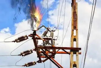
The most common fault categories include open-circuit faults, short-circuit faults, and ground faults. An open circuit fault occurs when a break in the circuit prevents current from flowing. A short circuit occurs when an unintended connection between two points allows an excessive amount of current to flow. A ground fault occurs when an unintended connection between the electrical circuit and the ground creates a shock hazard. Faults often relate to excessive current flow, which can be better understood through Ohm’s Law and its role in determining resistance, voltage, and current relationships.

A balanced fault is a condition in which all three phases of a three-phase system are shorted to ground or to each other. In this type of fault, the system remains balanced, and the fault current is limited. Understanding basic electricity is essential to grasp how faults disrupt the normal flow of current in a circuit.


Classifications of Electrical Faults

Electrical faults can be categorized into several groups to help engineers understand their causes and plan effective protective measures.

Transient vs. Permanent Faults: Transient faults, such as those caused by a lightning strike or temporary contact with a tree branch, clear on their own once the source is removed. Permanent faults, on the other hand, require repair before normal operation can resume, such as when insulation fails or a conductor breaks.

Symmetric vs. Asymmetric Faults: A symmetric fault affects all three phases of a system equally, and although rare, it can cause severe damage due to the high fault currents it generates. Asymmetric faults are far more common, involving one or two phases, and they create an unbalanced condition in the system.

Internal vs. External Faults: Internal faults occur within equipment, such as transformers, generators, or motors, often due to insulation breakdown or winding damage. External faults originate outside the equipment, caused by conditions such as storm damage, contact with foreign objects, or human error.


Types of Electrical Faults in Power Systems

A line-to-ground fault occurs when one of the conductors in a circuit comes in contact with the ground. This can happen due to faulty insulation, damaged equipment, or environmental conditions. A common example is a lightning strike creating a transient line-to-ground fault that trips breakers on a distribution system.

Other major types include:

  • Line-to-ground: conductor touches ground, causing shock risk

  • Open circuit: broken wires or components stop current flow

  • Phase fault: phases contact each other or ground

  • Short circuit: an unintended connection allows excessive current

  • Single-phase: limited to one phase, but still damaging

  • Arc fault: current jumps an air gap, creating sparks and fire risk

  • Balanced vs unbalanced: equal current in phases vs uneven distribution

Rodents chewing through insulation in attics or utility spaces often cause arc faults, showing how even small intrusions can lead to dangerous electrical events. When discussing ground faults and protective systems, it’s useful to revisit the conductor definition, since conductors are the pathways through which electrical energy travels and where faults typically occur.


Electrical Fault Protection Systems and Safety Devices

A circuit breaker is a device that automatically interrupts the flow of current in a circuit when it detects a fault. It is an essential safety device that helps prevent fires and other hazards.

When a circuit is interrupted, the flow of current in the circuit is stopped. This can happen for various reasons, including a circuit fault, a switch or breaker opening, or other similar issues.

In an electric power system, faults can cause significant damage to system equipment and result in power outages. Power system equipment includes transformers, generators, and other devices that are used to generate, transmit, and distribute power.

  • Circuit breakers: interrupt current when faults are detected

  • Relays: monitor and signal breakers to operate

  • Fuses: provide overcurrent protection in smaller systems

  • GFCIs: stop leakage current to ground instantly

  • AFCIs: detect arc faults to prevent electrical fires

Modern protective relay schemes, such as distance relays, differential relays, and overcurrent relays, provide precise and selective fault detection in high-voltage power systems. Engineers also use fault current analysis and time–current coordination studies to ensure that devices operate in the right order, isolating only the affected portion of the network.

Voltage drop refers to the reduction in voltage that occurs when current flows through a circuit. Various factors, including the resistance of the circuit components and the distance between the power source and the load, can cause voltage drops. Many fault events lead to abnormal heating or circuit interruption, highlighting the importance of electrical resistance and how it affects system reliability.


Signs, Hazards & Prevention

Electrical hazards refer to any situation or condition that poses a risk of injury or damage. Various factors, including faulty equipment, damaged insulation, or human error, can cause hazards. Faulty wiring refers to any damaged, frayed, or deteriorated wiring. Faulty wiring can cause faults and create safety hazards for people nearby.

The signs of a fault can vary depending on the type of fault and its location. However, some common signs include flickering lights, frequent circuit breaker trips, burning odours, and overheating equipment.

  • Warning signs: flickering lights, breaker trips, overheating, burning odours

  • Safety hazards: electric shock, fire, equipment damage

  • Prevention steps: inspections, correct equipment sizing, avoiding overloads, and code compliance

It is crucial to follow proper safety practices to prevent faults from occurring. This includes regular maintenance and inspection of equipment, using the correct type and size of electrical components, and avoiding overloading circuits. It is also essential to use circuit breakers, GFCIs, and other protective devices as required by code. For a broader perspective, exploring the dangers of electricity helps explain why protective devices and fault detection are so critical for both personal safety and equipment protection.


Frequently Asked Questions
 

How do faults occur?

Faults can occur for various reasons, including equipment failure, environmental conditions, and human error. Some common causes of faults include faulty wiring, damaged insulation, overloaded circuits, lightning strikes, power surges, and voltage fluctuations.


What are the most common types of faults?

The most common types of faults include open-circuit faults, short-circuit faults, and ground faults.


What are the signs of a fault?

The signs of a fault can vary depending on the type of fault and its location. However, some common signs of an electrical fault include flickering lights, circuit breakers tripping frequently, burning smells, and overheating equipment.


How can you prevent faults from occurring?

It is crucial to follow proper safety practices to prevent faults from occurring. This includes regular maintenance and inspection of equipment, using the correct type and size of electrical components, and avoiding overloading circuits. It is also essential to use circuit breakers and other protective devices.


Related Articles


View more

Sign Up for Electricity Forum’s Newsletter

Stay informed with our FREE Newsletter — get the latest news, breakthrough technologies, and expert insights, delivered straight to your inbox.

Electricity Today T&D Magazine Subscribe for FREE

Stay informed with the latest T&D policies and technologies.
  • Timely insights from industry experts
  • Practical solutions T&D engineers
  • Free access to every issue

Download the 2025 Electrical Training Catalog

Explore 50+ live, expert-led electrical training courses –

  • Interactive
  • Flexible
  • CEU-cerified