Understand How To Test a Transformer
By William Conklin, Associate Editor

Substation Maintenance Training
Our customized live online or in‑person group training can be delivered to your staff at your location.

- Live Online
- 12 hours Instructor-led
- Group Training Available
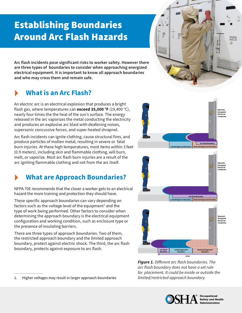
Download Our OSHA 4474 Fact Sheet – Establishing Boundaries Around Arc Flash Hazards

- Understand the difference between arc flash and electric shock boundaries
- Learn who may cross each boundary and under what conditions
- Apply voltage-based rules for safer approach distances
Learn how to test a transformer: insulation resistance, TTR, winding resistance, polarity, continuity, and dielectric checks. Confirm condition, find faults, and keep safe with a multimeter, megohmmeter, and clear procedures for field work on site.
How to Test a Transformer?
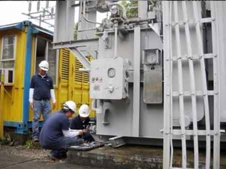
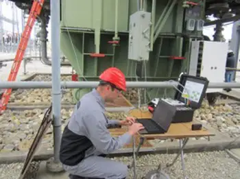
How to test a transformer is a practical process of verifying a unit’s health and safety through standard electrical tests—insulation resistance, turns ratio, winding resistance, and polarity—and documenting the results against the nameplate and manufacturer's limits.
-
Safety first: de-energize, lockout/tagout, discharge capacitors, verify absence of voltage
-
Perform IR (megohmmeter), TTR, winding resistance, polarity/phase, basic functional checks
-
Record readings, compare with specs and trends; decide on repair, drying, or replacement
Electrical Transformer Maintenance Training
Substation Maintenance Training
Request a Free Training Quotation
How to test a transformer is a crucial step in ensuring reliability, safety, and compliance with electrical standards. Whether in the field or at the shop, routine checks help identify faults, extend service life, and prevent costly failures. A thorough procedure involves a combination of visual inspection, standard electrical measurements, advanced diagnostic tests, and careful interpretation of the results. Proper testing procedures often depend on transformer design, so reviewing the construction of a transformer can provide valuable context.
Visual Inspection and Pre-Check Steps
Before applying any test instrument, always begin with a close inspection. Look for oil leaks, bulges, burn marks, corrosion, or cracked bushings. Dirt, dust, and moisture on terminals can compromise insulation and give false readings. Confirm that nameplates are intact and legible. These steps cost little time but often reveal issues long before instruments are connected. Field testing often reveals issues with insulation and winding integrity, which makes knowledge of transformer insulation essential for interpreting results.
Electricity Today T&D Magazine Subscribe for FREE

- Timely insights from industry experts
- Practical solutions T&D engineers
- Free access to every issue

How to test a transformer: Safety and Preparation
Safety comes first. De-energize the transformer, lock out/tag out all sources, and verify the absence of voltage. Discharge stored energy in capacitors and ground the windings. Use personal protective equipment (PPE) appropriate to the transformer’s voltage class. Ensure your test instruments—megohmmeters, multimeters, or resistance bridges—are calibrated and leads are intact. Skipping these basics risks inaccurate data or dangerous accidents. Testing steps vary for dry-type, oil-filled, and distribution units, which is why knowledge of the distribution transformer is essential for field technicians.
Standards and Specifications
Accurate testing means knowing what values are acceptable. IEEE, IEC, and national codes outline limits for insulation resistance, turns ratio, and dielectric strength. For example, insulation resistance values are corrected to 20 °C to ensure proper comparison with manufacturer data. Turns ratio should not deviate more than about ±0.5% from the nameplate, depending on class. Always record ambient conditions, as results depend heavily on temperature and humidity.
How to Test a Transformer: Comparison of Test Methods
| Test Name | Purpose | Procedure | Key Indicators / Results |
|---|---|---|---|
| Insulation Resistance (IR) | Checks insulation health between windings and ground | Apply DC voltage with a megohmmeter, record values at 15s, 1m, 10m | High resistance (MΩ) = good; low values or downward trend = moisture or insulation failure |
| Turns Ratio Test (TTR) | Verifies correct ratio between primary and secondary windings | Apply test voltage across primary and measure secondary | Ratio should match nameplate within ±0.5% (varies by standard) |
| Winding Resistance | Detects shorted turns, loose connections, or poor joints | Measure resistance with DC bridge or micro-ohmmeter | Balanced values across phases; high or unequal readings suggest defects |
| Polarity & Phase Check | Ensures windings are correctly oriented for parallel operation | Apply low AC voltage, observe phasing or use test set | Proper polarity and phase alignment; incorrect results prevent safe paralleling |
| Continuity | Confirms windings are continuous and not open-circuited | Use multimeter to measure continuity across windings | Continuous reading = intact winding; open = fault present |
| No-Load & Load Loss Tests | Evaluates efficiency, core and copper losses | Energize at rated voltage (no-load) or rated current (load) | Acceptable loss values within manufacturer limits |
| Dielectric Withstand (Hipot) | Proves insulation can handle overvoltage | Apply test voltage above operating level for set duration | No breakdown or flashover during test = pass |
| Short-Circuit Test | Determines impedance and short-circuit strength | Apply reduced voltage until rated current flows | Impedance matches design; abnormal = winding issues |
| Oil/Fluid Analysis | Assesses liquid insulation condition in oil-filled units | Sample oil, test for gases, moisture, acidity, dielectric strength | High gas/moisture/acidity = aging or fault; strong dielectric = healthy oil |
| Partial Discharge Test | Detects early-stage insulation defects | Apply AC voltage and monitor discharge signals | Low or no discharge = good; high activity = insulation breakdown risk |
Core Electrical Tests
Once the visual checks and safety steps are complete, the next stage involves conducting the standard tests that provide a baseline assessment of the transformer's condition. When performing load and no-load loss tests, it is helpful to understand the transformer core, as its design directly impacts efficiency and measurement accuracy. These are the essential diagnostic methods most technicians rely on:
-
Insulation Resistance (IR): Measured with a megohmmeter at voltages matched to the winding class. Record readings at 15 seconds, 1 minute, and 10 minutes to calculate polarization index (PI) or dielectric absorption ratio (DAR).
-
Turns Ratio Test (TTR): Confirms that the primary-to-secondary voltage ratio matches design. Significant deviation may indicate shortened turns.
-
Winding Resistance: Performed with DC bridges or micro-ohmmeters, corrected for temperature, and compared across phases and tap positions.
-
Polarity and Phase Check: Ensures correct connection orientation, critical when paralleling units.
-
Continuity: Confirms that windings and tap changers are intact and not open-circuited.
Advanced and Supplemental Tests
For a more complete picture of transformer health, advanced tests go beyond the basics and can uncover hidden problems. These are typically carried out during factory acceptance or major maintenance intervals:
-
No-Load and Load Loss Tests: Measure excitation current, core losses, impedance, and copper losses.
-
Dielectric Withstand (Hipot): Applies a voltage higher than the operating voltage to verify insulation integrity.
-
Short-Circuit Tests: Determine impedance and identify weak points.
-
Oil or Fluid Analysis: For liquid-filled transformers, dissolved gas analysis or dielectric fluid testing reveals insulation breakdown.
-
Partial Discharge Tests: Detect microscopic insulation defects before they escalate.
Measurement Techniques and Best Practices
The accuracy of results depends heavily on how tests are conducted. Following consistent methods ensures readings are comparable over time:
-
Connect the megger leads with proper grounding, ensuring the other windings are shorted and grounded during IR tests.
-
Allow time for the transformer to stabilize after de-energization before resistance checks.
-
Record temperature with every test, since winding resistance and insulation behaviour vary with heat.
-
When measuring IR, note time-based values for PI or DAR analysis; a PI below 2 typically signals deteriorating insulation.
Interpretation of Results
Numbers alone mean little without proper context. Once results are collected, the following principles help interpret them effectively:
-
Compare results with manufacturer data, industry standards, and previous test records.
-
Watch for declining insulation resistance trends, even within acceptable limits, as they may point to moisture ingress.
-
Check for unbalanced winding resistance, which could indicate loose connections or partial shorts.
-
Evaluate deviations in TTR: small shifts may be tolerable, but large errors signal winding problems.
Many failures detected during transformer testing are related to overheating; therefore, combining tests with preventive practices, such as maintenance inspection windows on transformers, improves long-term reliability.
Next Steps When Tests Fail
If a transformer fails to meet the expected standards, corrective action is necessary. Depending on the results, steps may include:
-
Drying out moisture with heaters or using a vacuum dryer.
-
Repairing bushings, gaskets, or connections.
-
Replacing or filtering insulating oil.
-
Rewinding or replacing the unit in cases of major internal faults.
Context Matters
Not all transformers are tested the same way. Distribution transformers, small dry types, and large power transformers each require different approaches and acceptance values. Match your testing plan to the transformer’s design, voltage class, and service environment. Oil-filled units require specialized fluid checks, making transformer oil analysis a critical extension of electrical testing. To fully verify safety margins, testing should be combined with knowledge of transformer overcurrent protection, which determines how protective devices respond under fault conditions.
Sign Up for Electricity Forum’s Utility Transformers Newsletter
Stay informed with our FREE Utility Transformers Newsletter — get the latest news, breakthrough technologies, and expert insights, delivered straight to your inbox.
How to test a transformer is more than connecting a megger or multimeter. It is a structured process of inspection, safety, measurement, interpretation, and corrective action. By including both standard checks and advanced diagnostic methods, and by aligning results with industry standards, electrical professionals can safeguard assets, protect personnel, and ensure system reliability.
Related Articles


