What is an Electrical Circuit?

By R.W. Hurst, Editor


what is an electrical circuit

An electrical circuit is a closed loop that allows electric current to flow through conductors, power sources, and loads. Circuits connect electrical devices, enable energy transfer, and ensure safe operation in homes, industries, and power systems.


What is an Electrical Circuit?

An electrical circuit is a path through which electricity flows from a power source to one or more devices that are connected.

✅ Provides controlled current flow through conductors

✅ Powers electrical devices safely and efficiently

✅ Includes sources, loads, and protective components

Gaining a grasp of the basic electricity of electrical circuits, including series and parallel configurations, voltage, current, resistance, Ohm's Law, and circuit analysis techniques, is vital for anyone interested in electronics, electrical engineering, or the inner workings of modern technology.


Core Components & Function

In order to understand what an electrical circuit is, one must appreciate that, 

At its core, an electrical circuit is a closed loop or pathway that facilitates the flow of electric current. This concept is essential in electronics and electrical engineering, as it provides the basis for the operation of everyday items, including smartphones, computers, and home appliances.

Within an electrical circuit, components are connected via conductive materials, such as wires, which enable the movement of electrons from a power source to other components and back.

The primary components of an electrical circuit include a power source (e.g., a battery or power supply unit), conductive materials (typically wires), a load (such as a resistor, motor, or light bulb), and a control element (for example, a switch). The power source supplies the voltage necessary for electric current flow, while the load transforms electrical energy into other forms, such as light or heat. Meanwhile, the control element permits the user to initiate or halt the flow of electrons, effectively turning a device on or off.

  • For students, a simple example is a battery connected to an LED, which demonstrates how electricity creates light.

  • For professionals, an industrial motor powered by a control circuit shows how electrical energy drives large-scale equipment.


Circuit Types (Series vs. Parallel)

Electrical circuits can be classified into three main types: series, parallel, and combination circuits.

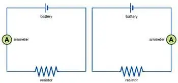
  • Series circuits connect components end-to-end, allowing current to flow sequentially through each one. Example: holiday string lights, where a single bulb outage can disrupt the entire circuit.

  • Parallel circuits enable current to flow through multiple paths. Example: household wiring, where turning off one light doesn’t affect others.

  • Combination circuits mix both series and parallel configurations to handle more complex systems.


Fundamental Laws (Ohm’s Law, Kirchhoff’s Laws)

A fundamental understanding of voltage, current, and resistance is crucial for comprehending electrical circuit operations.

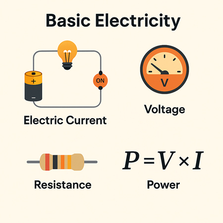
Voltage, the driving force that propels electric charge through a circuit, and current, the flow of electric charge measured in amperes (A), are closely related to resistance. Resistance, expressed in ohms (Ω), represents the opposition to the flow of current. These elements are interconnected through Ohm's law, which states that the voltage across a conductor is directly proportional to the current it carries and inversely proportional to its resistance: V = IR, where V represents voltage, I denotes current, and R represents resistance. Understanding how current creates magnetic fields is explained by Ampere's Law, which forms the basis for analyzing electromagnetism in electrical circuits.

Circuit analysis determines the current, voltage, and power associated with each component in an electrical circuit. Techniques such as Kirchhoff's Law of voltage and current, Thevenin's theorem, and Norton's theorem are employed to analyze and resolve electrical circuit issues. These methods enable engineers to design and troubleshoot electronic devices and systems effectively.


Thevenin's Theorem

Thevenin's theorem is a fundamental principle in electrical engineering and circuit analysis. It is a powerful technique to simplify complex linear circuits, making it easier to analyze and calculate the current, voltage, and power across specific components. The theorem is named after the French engineer Charles Léonard Siméon Thévenin, who proposed it in 1883.


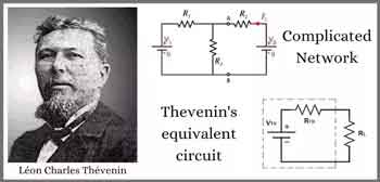
Thevenin's theorem states that any linear, active, bilateral network containing voltage sources, current sources, and resistors can be replaced by an equivalent circuit consisting of a single voltage source (called Thevenin's voltage, Vth) in series with a single resistor (called Thevenin's resistance, Rth) connected to the terminals of the original circuit. This simplified circuit, known as the Thevenin equivalent circuit, can then be used to analyze the behaviour of the original circuit with a specific load connected to its terminals.

Steps to apply Thevenin’s theorem:

  1. Identify the portion of the circuit you want to simplify and the terminals where the load will be connected.

  2. Remove the load from the terminals (if present) and leave the terminals open-circuited.

  3. Calculate the open-circuit voltage across the terminals. This value is Thevenin's voltage (Vth).

  4. Calculate the equivalent resistance seen from the open-circuited terminals with all independent voltage sources replaced by short circuits (zero resistance) and all independent current sources replaced by open circuits (infinite resistance). This value is Thevenin's resistance (Rth).

  5. Create the Thevenin equivalent circuit using the calculated Vth and Rth values, then connect the original load across the terminals.

Once the Thevenin equivalent circuit is determined, you can easily analyze the circuit's behaviour and calculate the current through the load, the voltage across the load, or even the power delivered to the load. This technique is particularly useful when analyzing circuits with varying loads or examining the circuit's behaviour at multiple points, as it simplifies calculations and saves time.


Norton’s Theorem

Norton's theorem is a fundamental principle in electrical engineering and circuit analysis that simplifies the analysis of complex linear circuits. Named after the American engineer Edward Lawry Norton, who introduced it in the early 20th century, the theorem is a counterpart to Thevenin's theorem.


While Thevenin's theorem reduces a complex network to an equivalent voltage source in series with a resistor, Norton's theorem simplifies the network to an equivalent current source parallel to a resistor.

Norton's theorem states that any linear, active, bilateral network containing voltage sources, current sources, and resistors can be replaced by an equivalent circuit consisting of a single current source (called Norton's current, IN) in parallel with a single resistor (called Norton's resistance, RN) connected to the terminals of the original circuit.

Steps to apply Norton’s theorem:

  1. Identify the portion of the circuit you want to simplify and the terminals where the load will be connected.

  2. Remove the load from the terminals (if present) and leave the terminals open-circuited.

  3. Calculate the short-circuit current flowing between the terminals. This value is Norton's current (IN).

  4. Calculate the equivalent resistance seen from the open-circuited terminals with all independent voltage sources replaced by short circuits (zero resistance) and all independent current sources replaced by open circuits (infinite resistance). This value is Norton's resistance (RN). Note that Norton's resistance is equal to Thevenin's, as both are calculated similarly.

  5. Create the Norton equivalent circuit with the calculated IN and RN values, connecting the original load across the terminals.

Once the Norton equivalent circuit is established, you can easily analyze the circuit's behaviour and calculate the current through the load, the voltage across the load, or even the power delivered to the load. Like Thevenin's theorem, Norton's theorem is particularly useful when dealing with varying loads or analyzing a circuit's behaviour at multiple points. In addition, it simplifies calculations, conserving time and effort.


Circuit Diagrams & Symbols

Circuit diagrams, also known as schematic diagrams, are graphical representations of electrical circuits that utilize standardized symbols to depict components such as resistors, capacitors, inductors, diodes, and transistors. These symbols facilitate the interpretation of a circuit's structure and function by engineers or hobbyists without requiring physical examination of the actual components.

Here are some common symbols used in circuit diagrams:

Resistor: A simple zigzag line represents a resistor, which opposes the flow of electric current and dissipates energy in the form of heat.

Capacitor: Two parallel lines with a small gap represent a capacitor. The positive plate is marked with a "+" sign in polarized capacitors, and a curved line represents the negative plate.

Inductor: A series of curved or looped lines, similar to a coil, represents an inductor, which stores energy in a magnetic field and opposes changes in current.

Diode: A triangle pointing to a line represents a diode, which allows current to flow in one direction but blocks it in the opposite direction.

Light-emitting diode (LED): Similar to a diode symbol, but with two arrows pointing away from the triangle, representing light emission.

Transistor: Two types of transistors are commonly used: bipolar junction transistors (BJTs) and field-effect transistors (FETs). A BJT symbol comprises a circle or rectangle with three connected leads (emitter, base, and collector). FET symbols are represented by a combination of lines and a vertical arrow with three terminals (gate, source, and drain).

Integrated circuit (IC): A rectangular or square box with multiple leads connected represents an integrated circuit, a complex assembly of numerous electronic components within a single package.

Battery: Alternating long and short parallel lines represent a battery, a source of electrical energy.

Power supply: A circle with an arrow pointing upwards or a combination of letters, such as "Vcc" or "+V," represents a power supply, which provides a constant voltage or current.

Switch: A break in line with an angled line nearby or a pair of lines connected by a diagonal line represents a switch, which controls the flow of current by making or breaking a circuit.

Ground: A series of horizontal lines that decrease in length, a downward-pointing arrow, or the letters "GND" represent a ground connection, which serves as a reference point and provides a return path for electrical currents.

These are just a few examples of the many symbols used in circuit diagrams. Therefore, it's essential to familiarize yourself with these symbols to read or create schematic diagrams for electrical or electronic circuits. The ability of a circuit to store electrical charge is described by Capacitance, a key principle in both electronics and power systems.


Practical Applications & Examples

Electrical circuits form the foundation of modern technology, enabling us to harness electricity to operate a wide range of devices and systems. From smartphones and computers to household appliances and industrial machines, circuits power nearly every aspect of daily life.

For example, a simple battery connected to a light bulb demonstrates how a closed loop allows current to flow, converting electrical energy into light and heat. Safe return paths for current are established through the proper installation of Grounding Electrode Conductors, which helps prevent shock and equipment damage.


Frequently Asked Questions


What is the simplest electrical circuit?

The simplest circuit consists of a power source (such as a battery), a conductor (like a wire), and a load (like a bulb). Closing the loop lets current flow and power the load.


How do series and parallel circuits differ in real life?

Series circuits share a single path, so if one component fails, the entire circuit stops. Parallel circuits have multiple paths, allowing devices to operate independently.


Why is grounding important in electrical circuits?

Grounding provides a safe return path for electricity. It reduces shock hazards and prevents equipment damage during faults or surges.


What role does resistance play in a circuit?

Resistance controls the amount of current flowing. High resistance limits current, while low resistance allows more current to pass.


What is the function of a circuit breaker or fuse?

These protective devices interrupt the current when it becomes too high, preventing overheating, fires, and damage to equipment. To safeguard devices and wiring from excessive currents, engineers rely on Overcurrent Protection Device such as fuses and circuit breakers.


What is an electrical circuit? Why It Matters

Electrical circuits are the backbone of modern technology, powering everything from smartphones and appliances to industrial systems. A firm grasp of fundamental circuit principles is crucial for engineers, electricians, and hobbyists, as it unlocks a deeper understanding of the devices that shape everyday life.


Related Articles


Related News

What do Ammeters Measure?

An ammeter measures electric current in a circuit, displayed in amperes (A). Connected in series with low internal resistance to reduce burden voltage, it ensures accurate readings for testing, fault detection, and diagnostics.


What do Ammeters Measure?

Ammeters are measuring devices that measure the flow of electricity in the form of current in a circuit.

✅ Measure electric current in amperes, connected in series with low internal resistance to minimize burden voltage.

✅ Available in analog, digital, clamp, and current transformer designs.

✅ Used for testing, fault detection, continuity checks, and diagnostics.

Electrical currents are then measured in the form of amperes, hence the name "ammeter". The term "ammeter" is sometimes used incorrectly as "ampmeter". Understanding how an ammeter works is easier when you first explore the basics of electricity fundamentals, including how voltage, current, and resistance interact in a circuit.

An ammeter measures electric current in a circuit, expressed in amperes (A). It must be connected in series with the load so that all the current flows through it, and is designed with low internal resistance to minimize burden voltage, thereby ensuring accurate readings without significantly affecting the circuit’s performance. The measurement unit for an ammeter is the ampere, explained in detail on our what is an ampere page, which also covers its relationship to other electrical units.

Ammeters are designed (as well as ohmmeters and voltmeters) to be used with a sensitive current detector such as a moving coil in a galvanometer. To measure the electric current flow through it, an ammeter is placed in series with a circuit element. The ammeter is designed to offer very low resistance to the current, so that it does not appreciably change the circuit it is measuring. To do this, a small resistor is placed in parallel with the galvanometer to shunt most of the current around the galvanometer. Its value is chosen so that when the design current flows through the meter, it will deflect to its full-scale reading. A galvanometer's full-scale current is very small: on the order of milliamperes. To see how ammeters fit into broader measurement tools, check out our guide on what is a voltmeter and what is a multimeter, which measure multiple electrical properties.

An Ammeter is analog. It is not mechanical or digital. It uses an analog-to-digital converter (ADC) to measure the voltage across the shunt resistor. The ADC is read by a microcomputer that performs the calculations to display the current through the resistor.


How an Ammeter Works

An ammeter works by being placed in series with the circuit so that all the current flows through it. Inside, a shunt resistor with very low internal resistance creates a small, measurable voltage drop proportional to the current. In analog designs, this current is partly diverted around a sensitive moving-coil mechanism, which displays the reading on a scale. In digital designs, the voltage drop across the shunt is measured by an analog-to-digital converter (ADC) and calculated into an amperes value, ensuring accurate measurement without significantly disturbing the circuit’s performance. Accurate current measurement also depends on understanding what is electrical resistance and how it affects current flow, especially in low-resistance ammeter designs.


Types and Mechanisms

Analog ammeter – Includes moving-coil (D'Arsonval) and moving-iron types, which use magnetic deflection to display current on a scale. These designs are valued for their simplicity, durability, and ability to provide continuous current readings.

Digital ammeter – Uses a shunt resistor to create a small voltage drop proportional to the current. This voltage is measured by an analog-to-digital converter (ADC) and displayed as a precise digital value. Digital ammeters often feature higher accuracy, wider measurement ranges, and additional functions such as data logging.

Clamp meter – Measures current without breaking the circuit by detecting the magnetic field around a conductor. This method is ideal for quick testing, especially in high-current applications or where live connections cannot be interrupted.

Current transformer (CT) ammeter – Designed for high-current AC systems, this type uses a transformer to scale down large primary currents into a safe, measurable secondary current for the meter.


Shunts and Operation

A shunt resistor is a precision, low-resistance component used in many ammeters. In analog designs, it is placed in parallel with the meter movement, diverting most of the current to protect the instrument. In certain digital designs, it is placed in series with the circuit. By measuring the voltage drop across the shunt and applying Ohm’s law, the meter accurately calculates the current. This approach allows for measurement of very large currents without damaging the meter and helps maintain measurement stability.


Applications and Value

Ammeters are essential tools in electrical testing, short-circuit detection, continuity testing, and system diagnostics. They help identify overloads, open circuits, and unstable current conditions that may indicate equipment faults or inefficiencies.

In industrial, commercial, and residential settings, ammeters are used for equipment maintenance, troubleshooting, and performance monitoring. Specialized variants such as milliammeters and microammeters are designed for extremely low current measurements, while integrating ammeters track current over time to determine total electrical charge delivered to a device or system. For historical context on the development of measuring instruments, visit our history of electricity page to learn how electrical science evolved over time.


Practical Applications of Ammeters

Ammeters are used in a wide range of electrical and electronic work:

  • Automotive diagnostics – Measuring current draw from the battery to detect parasitic drains, starter motor issues, and charging system faults.

  • Solar panel and battery monitoring – Tracking current output from photovoltaic arrays and the charging/discharging rates of storage batteries to optimize system efficiency.

  • Industrial motor maintenance – Monitoring motor current to identify overload conditions, detect bearing wear, or confirm correct load operation.

  • Household appliance servicing – Checking current draw to troubleshoot faulty components or ensure devices operate within safe limits.

  • Power distribution systems – Ensuring current levels remain within capacity for cables, fuses, and protective devices.


Related Articles


View more

What is Considered High Voltage? HV Applications Explained

What is considered high voltage? Per IEC/IEEE, voltages above 1 kV AC or 1.5 kV DC; linked to insulation coordination, arc-flash risk, transmission lines, substations, switchgear ratings, clearance/creepage distances, and dielectric breakdown in power systems.


What Is Considered High Voltage?

Voltages above 1 kV AC or 1.5 kV DC are classed as high voltage per IEC/IEEE in power systems.

✅ IEC/IEEE: >1 kV AC or >1.5 kV DC thresholds

✅ Categories: MV, HV, EHV, UHV in power transmission

✅ Impacts insulation, clearance, arc-flash, switchgear ratings


What is Considered High Voltage?

In the world of electrical engineering, understanding voltage levels is crucial. So you might be asked to define high voltage. But what is considered HV? This article explores the definition, classification, and applications of HV and the safety concerns and precautions that come with it. For foundational context, the concept of voltage underpins how these levels are defined and compared across systems.


According to the International Electrotechnical Commission (IEC), HV is typically defined as any voltage above 1000 volts for alternating current (AC) systems and 1500 volts for direct current (DC) systems. However, the term "HV" can also refer to voltages as low as 50 volts in some safety regulations, depending on the context. For example, the US Occupational Safety and Health Administration (OSHA) defines HV as 600 volts or higher in their safety guidelines. Standards often reference nominal voltage values that guide equipment ratings, insulation clearances, and test criteria in practice.

High voltage systems are essential in electric power transmission and distribution, allowing electricity to be transported over long distances with minimal energy loss. Power lines, transmission lines, and transformers all play a role in the power transmission and distribution process. Transformers are used to step up or down voltage levels, depending on whether the electricity is transported over long distances or distributed to end-users. At the point of use, networks step down to low voltage levels suitable for residential and commercial equipment before final delivery.

Voltage classification is a method for organizing voltages based on their range. There are four primary classifications of voltage levels: low (LV), medium  (MV), HV, and extra HV (EHV). Ultra HV (UHV) is another classification for exceptionally high voltages, typically used in long-distance power transmission projects. In distribution grids, medium voltage tiers bridge the gap between long-distance transmission and local feeders in a coordinated hierarchy.

Insulation is a crucial aspect of HV systems, as it prevents electrical current from leaking and causing short circuits, equipment damage, or even fires. Different types of insulation are used depending on the voltage level and application, such as air, gas, oil, or solid materials like plastics and ceramics. For clarity on terminology used in insulation, dielectric strength, and creepage distances, consult common electricity terms that standardize communication across projects.

HV circuits and equipment, such as transformers and switchgear, are designed to handle higher voltages safely and efficiently. These devices are essential components of power distribution networks and are subject to strict design, manufacturing, and testing standards to ensure reliability and safety.

Working with high voltage circuits presents several electrical hazards, such as electric shock, arc flash, and fires. To mitigate these risks, electrical safety measures must be put in place. Workers with HV equipment must follow safety procedures and use appropriate personal protective equipment (PPE), such as insulated gloves, safety glasses, and arc flash suits. Comprehensive electricity safety programs integrate procedures, labeling, lockout/tagout, and training to reduce incident rates.

So, what is considered high voltage? As mentioned earlier, the IEC defines HV as 1000 volts for AC and 1500 volts for DC. However, some safety regulations might consider voltages as low as 50 or 600 volts as HV.

HV is used in power transmission and distribution to transport electricity efficiently over long distances. Transmission lines, transformers, and other equipment are designed to handle HVs and are integral to power distribution networks.

Safety concerns associated with HV systems include electric shock, arc flash, and fires. Proper safety procedures and protective equipment are necessary to minimize these risks. Understanding the broader dangers of electricity helps contextualize HV-specific risks and informs mitigation strategies.

Transformers handle HV levels by stepping up or stepping down the voltage, allowing for efficient power transmission and distribution. They are designed to withstand HV stresses and are subject to rigorous testing and standards.

Various types of insulation are needed for HV applications, including air, gas, oil, and solid materials like plastics and ceramics. The choice of insulation depends on the level and specific application requirements.

The different classifications of voltage levels include low, medium, HV, extra HV, and ultra HV. These classifications help categorize voltage ranges for various applications and safety standards.

When working with HV equipment, workers should follow safety procedures, use appropriate personal protective equipment, and undergo regular training to stay updated on best practices and safety guidelines.

In conclusion, understanding what is considered HV is crucial for electrical systems' safe and efficient operation. HV plays a vital role in power transmission and distribution, allowing electricity to be transported over long distances with minimal losses. Proper insulation, transformers, and other equipment are designed to handle HV levels and ensure the reliability of the electrical infrastructure. Safety concerns associated with HV systems must be addressed through stringent safety procedures, protective equipment, and worker training. We can maintain a safe and efficient electrical infrastructure by adhering to these guidelines and understanding the importance of classifications.


High, Extra-High and Ultra-HV Classifications

High, extra-high, and ultra-high voltage classifications are categories used to define the levels within electrical systems, particularly in power transmission and distribution networks. These classifications help standardize the design, manufacturing, and operation of electrical equipment and ensure safety and efficiency.


High Voltage (HV):

HV is typically defined as levels between 1000 volts (1 kV) and 100,000 volts (100 kV) for alternating current (AC) systems and between 1500 volts (1.5 kV) and 100,000 volts (100 kV) for direct current (DC) systems. HV systems are commonly used in electric power transmission and distribution networks, substations, and industrial facilities. HV allows for efficient power transmission over long distances while reducing energy loss due to resistance.


Extra-High Voltage (EHV):

Extra-high voltage refers to levels above 100,000 volts (100 kV) and up to 300,000 volts (300 kV) for AC systems and between 100,000 volts (100 kV) and 800,000 volts (800 kV) for DC systems. EHV systems are primarily used for long-distance power transmission, where higher levels reduce energy losses even further. EHV lines and equipment require specialized design, manufacturing, and maintenance to ensure safety, reliability, and efficiency. The use of extra-high voltage is also associated with more stringent safety protocols and larger right-of-way requirements for transmission lines.


Ultra-High Voltage (UHV):

Ultra-high voltage classification is designated for levels above 300,000 volts (300 kV) for AC systems and above 800,000 volts (800 kV) for DC systems. UHV systems are used in large-scale power transmission projects that aim to transmit massive amounts of electricity over very long distances with minimal losses. These projects typically connect major power generation sources, such as hydroelectric or nuclear plants, to far-off load centers or densely populated urban areas. As a result, UHV systems demand the highest level of engineering expertise, rigorous testing, and specialized equipment to ensure their safe and efficient operation.


Related Articles

View more

Capacitance in Parallel Explained

Capacitance in parallel occurs when capacitors are connected side by side, and their values add together. This increases total capacitance, ensures stable voltage, supports efficient charge distribution, and is essential in electronics, energy storage, and reliable circuit design.


What is Capacitance in Parallel?

Capacitance in parallel occurs when capacitors are connected across the same two points in a circuit, causing their capacitance to add up:

✅ Increases total capacitance by summing all capacitor values

✅ Improves energy storage and voltage regulation in circuits

✅ Common in AC and DC applications for a consistent charge supply

To learn the fundamentals, see what is capacitance, which explains how capacitors store charge, the role of farads, and why this property is essential in circuits and energy storage.


Understanding Parallel Capacitor Behavior

When capacitors are connected in parallel, the effective plate area increases, and the total capacitance is the sum of the individual capacitances. Figure 1 shows a simplified parallel circuit. The total charging current from the source divides at the junction of the parallel branches. To fully understand how capacitors behave in parallel, it helps to revisit the basics of what is a capacitor and how capacitance works in circuits. 


Fig. 1 - Simplified parallel circuit.


There is a separate charging current through each branch, allowing a different charge to be stored by each capacitor. Using Kirchhoff’s current law, the sum of all the charging currents is then equal to the total current. The sum of the charges (Q) on the capacitors is equal to the total charge on the capacitors. The voltages (E) across all of the parallel branches are equal. With all of this in mind, a general equation for capacitors in parallel can be determined as:

QT = Q1 + Q2 + Q3

Because Q = CE: CTET = C1E1 + C2E2 + C3E3

Voltages can be factored out because:

ET = E1 + E2 + E3

Leaving us with the equation for capacitors in parallel:

CT = C1 + C2 + C3

Consider the following example:

If C1 = 330μF, C2 = 220μF

Then CT = 330μF + 220μF = 550μF

To calculate the total capacitance in a parallel combination, you simply add the values of the individual capacitors together. This method is straightforward and differs from series connections, where the reciprocal of each capacitor must be used. The total increases with the number of capacitors added in parallel, making this configuration ideal for applications that require higher capacitance. When designing circuits, understanding how a parallel combination enhances energy storage compared to a series connection is crucial for selecting the optimal number of capacitors to achieve the desired performance. For a detailed breakdown of how capacitance is measured, check out the unit of capacitance to understand farads and their practical conversions.

Since voltage remains constant across parallel capacitors, a firm grasp of what is voltage and its behavior in different configurations is essential.


Capacitance in Alternating Current

If a source of alternating current is substituted for the battery, the capacitor acts quite differently than it does with direct current. When an alternating current is applied in the circuit, the charge on the plates constantly changes. [Figure 2] This means that electricity must flow first from Y clockwise around to X, then from X counterclockwise around to Y, then from Y clockwise around to X, and so on. Although no current flows through the insulator between the plates of the capacitor, it constantly flows in the remainder of the circuit between X and Y. In a circuit in which there is only capacitance, current leads the applied voltage, as contrasted with a circuit in which there is inductance, where the current lags the voltage. Capacitors in AC circuits are deeply influenced by alternating current, where the current leads the voltage due to capacitive reactance.


Fig. 2 - Capacitor in an AC circuit.

The parallel connection rule CT = C1 + C2 + C3 reflects the broader principles of resistances in parallel, though capacitance behaves in an additive way instead of being reciprocal.


Capacitive Reactance Xc

The effectiveness of a capacitor in allowing an AC flow to pass depends upon the capacitance of the circuit and the applied frequency. To what degree a capacitor allows an AC flow to pass depends largely upon the capacitive value of the capacitor, given in farads (F). The greater the capacitance, the greater the number of electrons, measured in coulombs, necessary to bring the capacitor to a fully charged state. Once the capacitor approaches or actually reaches a fully charged condition, the polarity of the capacitor will oppose the polarity of the applied voltage, essentially acting then as an open circuit.

To further illustrate this characteristic and how it manifests itself in an AC circuit, consider the following:
If a capacitor has a large capacitive value, a high-frequency current can alternate through it without the capacitor ever reaching a full charge. In this case, the capacitor may offer very little resistance to current.

However, the smaller the capacitance, the fewer electrons are required to bring it up to a full charge, and it is more likely that the capacitor will build up enough of an opposing charge to present significant resistance, possibly behaving like an open circuit. Understanding Kirchhoff’s Law helps explain how current divides among parallel capacitors and supports accurate calculations.


Comparison With Series Capacitance

Understanding the difference between series and parallel capacitance is critical for circuit design:

Configuration Total Capacitance Voltage Behavior Current Behavior
Parallel Adds directly: CT = C1 + C2 + ... Same across all components Divides among branches
Series Inverse sum: 1/CT = 1/C1 + 1/C2 + ... Divides across components Same through all components
  • Parallel is best when you want more capacitance and voltage stability.

  • Series is used when you need a lower total capacitance or to increase voltage tolerance.

To explore how capacitors behave when connected end-to-end, visit capacitance in series, which explains the reciprocal formula and voltage behavior.


Practical Design Considerations

  • Voltage Rating: In parallel, all capacitors share the same voltage. The lowest voltage rating among capacitors determines the safe operating voltage of the group.

  • Physical Size: Adding more capacitors increases board space. Designers must balance performance with space constraints.

  • Energy Storage: Parallel configurations store more energy, making them ideal for power supplies, smoothing circuits, and buffering in audio and RF systems.

Real-world circuit design also requires familiarity with types of capacitors, as their materials and tolerances affect total capacitance and performance.


Real-World Applications of Parallel Capacitors

  • Power Supply Smoothing: Bulk capacitors in parallel stabilize the DC output.

  • Decoupling Noise: Small-value capacitors placed in parallel with larger ones eliminate high-frequency interference.

  • Tuning Circuits: In radio circuits, variable capacitors, when used in parallel with fixed ones, help tune specific frequencies.

For a broader context, you can explore how electrical resistance and reactive power relate to capacitive elements in AC power systems.


Related Articles


View more

What is a Capacitor?

A capacitor is an electrical component that stores and releases energy in a circuit. It consists of two conductive plates separated by an insulator and is commonly used for filtering, power conditioning, and energy storage in electronic and electrical systems.


What is a Capacitor?

A capacitor is a key component in electronics and power systems. It temporarily stores electrical energy and is widely used in both AC and DC circuits.

✅ Stores and discharges electrical energy efficiently

✅ Used in filtering, timing, and power factor correction

✅ Found in electronics, motors, and power supplies

It is designed for energy storage and can store electric charges, which can be released when needed. In this article, we will delve into the fundamentals of capacitors, including their functions, types, and applications. To better understand how capacitors support overall system performance, explore our Power Quality overview covering the fundamentals of voltage stability and energy flow.

Power Quality Analysis Training

Power Factor Training

Request a Free Power Quality Training Quotation

A capacitor consists of two metallic plates separated by an insulating material known as the dielectric. The dielectric can be made from various materials, such as mica, paper, or ceramic. When voltage is applied across the plates, positive charges accumulate on one plate, while negative charges accumulate on the opposite plate. The amount of capacitor charge that can be stored depends on several factors, including plate area, plate separation, dielectric material, and voltage ratings. Capacitors are often used in capacitor banks to improve power factor and reduce energy losses in electrical systems.

How does a capacitor work? The primary function of a capacitor in an electronic circuit is to store electrical energy. Capacitors can be used for various purposes, such as filtering, timing, and coupling or decoupling signals. In addition, they play a crucial role in power supplies, ensuring that the output voltage remains stable even when there are fluctuations in the input voltage. Learn how capacitive loads influence circuit behavior and why they require precise capacitor selection for optimal performance.

A capacitor stores energy through the electrostatic field created between its plates. The stored energy can be calculated using the formula E = 0.5 * C * V^2, where E is the stored energy, C is the capacitance, and V is the voltage across the capacitor. Capacitance, measured in Farads, is a measure of a capacitor's ability to store charge. The capacitor voltage rating is crucial for ensuring safe operation and preventing dielectric breakdown during voltage spikes.

So, when I am asked what is a capacitor? I tell readers about several types of capacitors, each with unique applications. Common types include ceramic, electrolytic, film, and tantalum capacitors. Ceramic capacitors are widely used due to their low cost and small size. They are ideal for high-frequency applications and decoupling in power supply circuits. On the other hand, Electrolytic capacitors are popular for their high capacitance values and are commonly used in filtering and energy storage applications. Capacitors play a crucial role in power factor correction, enabling industrial systems to reduce demand charges and enhance energy efficiency.

Dielectric materials used in capacitors can be organic (such as paper) or inorganic (such as ceramic). The choice of dielectric material depends on factors like the desired capacitance value, voltage rating, and operating temperature range. Additionally, different dielectric materials exhibit varying properties, making them suitable for specific applications. For a deeper understanding of energy relationships, see how apparent power differs from real and reactive power in systems using capacitors.

A capacitor can be classified as polarized or non-polarized based on the presence or absence of polarity. Polarized capacitors, like electrolytic capacitors, have a positive and a negative terminal and must be connected correctly in a circuit to function properly. Non-polarized capacitors, like ceramic capacitors, do not have a specific polarity and can be connected in any orientation.

A Capacitor behaves differently in AC and DC voltage circuits. In DC circuits, once a capacitor is charged, it blocks the flow of current, essentially acting as an open circuit. However, in ac voltage circuits, capacitors allow the flow of alternating current. This phenomenon is known as displacement current, which occurs due to the continuous charging and discharging of charges.

So, what is a capacitor? Understanding what a capacitor is and how it works is essential for anyone interested in electronics. The Capacitor plays a vital role in a wide range of applications, from energy storage and filtering to signal coupling and decoupling. Understanding the various types of capacitors and their specific applications enables you to make informed decisions when designing or troubleshooting electronic circuits. Explore how an automatic power factor controller dynamically adjusts capacitor usage to maintain an efficient power factor in real-time.


Related Articles


View more

What is an Arc Fault?

An arc fault is a dangerous electrical discharge between conductors or to ground. It generates intense heat and light, often caused by damaged insulation, frayed wires, or loose connections, posing major electrical safety and fire hazards.


What is an Arc Fault?

An arc fault is an unintended electrical discharge that occurs when insulation or wiring fails, producing dangerous heat that can ignite fires and damage circuits.

✅ Caused by frayed wires or loose connections

✅ Produces intense heat and light energy

✅ Prevented by Arc Fault Circuit Interrupters (AFCIs)


Basic Protection Relay Training

Short Circuit Study Training

Request a Free Training Quotation


Understanding Arc Faults and Electrical Safety

An arc fault is a hazardous electrical event that can lead to severe consequences, including fires and substantial property damage. Understanding how faults occur, how to prevent them, and why protective measures like Arc Fault Circuit Interrupters (AFCIs) are essential can significantly improve home and workplace safety.

When electrical current jumps across a gap or an unintended path, it forms an electric arc. This arc generates extremely high temperatures—often exceeding 10,000°F—capable of igniting nearby insulation, wood framing, or other combustible materials. Faults are typically caused by damaged, frayed, or aging wiring, loose terminal connections, or punctured cables from nails and screws during construction. For more insight into advanced safety devices, learn how an arc fault interrupter breaker detects hazardous arcing and disconnects power before a fire can start.

Arc fault protection is especially important in areas where people live and spend time, such as family rooms, dining rooms, and living rooms, where electrical wiring runs behind walls containing materials such as wood framing or insulation that can easily ignite. Modern safety standards, as mandated by the National Electrical Code, require the installation of Arc Fault Circuit Interrupters (AFCIs) in these spaces to prevent fires caused by faults. When combined with Ground Fault Circuit Interrupters, which protect against electrical shock, AFCIs provide comprehensive protection against both fire and shock hazards in residential and commercial environments.


Types of Arc Faults

Arc faults can appear in different forms, each with its own risks and detection requirements:

  • Series Faults – Occur along a single conductor, usually from a broken wire or loose terminal. These arcs produce less current but can still ignite fires.

  • Parallel Faults – Form between two conductors (hot-to-neutral or hot-to-ground). These faults create higher current levels and more intense arcing.

  • Ground Faults – Happen when current leaks or shorts to a grounded surface, such as a metal outlet box or appliance casing. Explore how ground fault protection complements AFCIs by guarding against current leakage that could cause electric shock or parallel arc conditions.

Recognizing these types helps electricians and inspectors identify the right protection strategies and select appropriate AFCI devices. To see how fault current behavior impacts fault risks, review our explanation of available fault current and why accurate short-circuit studies are essential for system safety.


How AFCI Detection Works

AFCIs are intelligent safety devices designed to detect the unique electrical signatures of faults. They continuously monitor current waveforms and frequencies, distinguishing dangerous arcs from normal switching arcs (such as those produced by light switches or vacuum cleaners).

When an AFCI identifies an abnormal frequency pattern consistent with arcing, it trips the circuit within milliseconds—disconnecting power before the fault can ignite a fire. This advanced “signature detection” technology is required by modern safety codes and has saved countless lives and properties. For more insight into advanced safety devices, learn how an arc fault interrupter breaker detects hazardous arcing and disconnects power before a fire can start.


Limitations and Nuisance Tripping

While AFCIs are highly effective, they can occasionally cause nuisance tripping. This occurs when the device misinterprets harmless electrical noise as a fault, typically triggered by motors, dimmers, or other electronic devices. Regular inspection, proper grounding, and updated AFCI models help minimize these false positives. If nuisance tripping persists, it’s advisable to have an electrician verify circuit wiring and device compatibility. To understand how electrical systems respond to fault conditions, refer to our detailed explanation of protective relay coordination, which ensures that circuit breakers isolate faults without disrupting unaffected circuits.


Code Requirements and Standards

Arc fault protection is mandated by both U.S. and Canadian electrical codes:

  • National Electrical Code (NEC 210.12) requires AFCI protection for all 120-volt, single-phase, 15- and 20-amp branch circuits supplying living areas such as bedrooms, family rooms, dining rooms, and similar spaces.

  • Canadian Electrical Code (CEC Section 26) similarly mandates AFCI in dwelling units.

  • IEEE 1584 provides calculation guidelines for flash hazards in industrial power systems, complementing residential and commercial fault safety standards.

Following these standards ensures compliance and dramatically reduces fire risks across residential, commercial, and industrial applications.


Statistics and Case Studies

According to the U.S. Consumer Product Safety Commission (CPSC), electrical fires cause over 51,000 residential fires annually, resulting in more than 500 deaths and $1.3 billion in property damage. Studies show that AFCI protection can prevent more than half of these incidents, highlighting its critical role in modern electrical safety systems.


Emerging Technologies in Arc Fault Detection

New generations of AFCIs utilize microprocessors and artificial intelligence to enhance accuracy and minimize false trips. These smart devices analyze waveform patterns with greater precision, detecting high-impedance arcs and subtle irregularities. Future technologies may integrate predictive analytics and IoT monitoring to diagnose potential faults before they become hazards. Finally, explore comprehensive methods of electrical surge protection, which safeguard sensitive equipment from voltage spikes often linked to lightning events.


Common Causes of Arc Faults

  • Damaged or aging electrical wiring

  • Loose terminal connections in outlets or switches

  • Overloaded circuits or faulty appliances

  • Nails or screws penetrating electrical cables

  • Deteriorated insulation from heat, moisture, or rodents

Regular maintenance and periodic inspections by a licensed electrician are essential preventive measures.


Arc Fault vs Ground Fault vs Short Circuit

Fault Type Description Main Hazard Protection Device
Arc Fault Unintended arcing between conductors or within wiring Fire risk AFCI
Ground Fault Current flowing to ground unintentionally Electric shock GFCI
Short Circuit Direct contact between conductors High current / equipment damage Circuit Breaker

Understanding these differences helps ensure that electrical protection systems are properly matched to the specific hazards they are intended to address.


Frequently Asked Questions


Why does my AFCI keep tripping?

Often due to electronic interference, shared neutrals, or actual wiring issues. Replace outdated AFCIs and consult a professional if tripping persists.


Can I retrofit AFCIs into older panels?

Yes. AFCI breakers can replace standard breakers in most modern panels. Have a qualified electrician confirm compatibility before installation.


Are AFCIs required everywhere?

While required in most living spaces, some regions exempt areas like garages or unfinished basements. Check the NEC or CEC requirements for your jurisdiction.


Related Articles


View more

What is a Watt? Electricity Explained

A watt is the standard unit of power in the International System of Units (SI). It measures the rate of energy transfer, equal to one joule per second. Watts are commonly used to quantify electrical power in devices, circuits, and appliances.


What is a Watt?

A watt is a unit that measures how much power is used or produced in a system. It is central to understanding electricity and energy consumption.

✅ Measures the rate of energy transfer (1 joule per second)

✅ Commonly used in electrical systems and appliances

✅ Helps calculate power usage, efficiency, and energy costs

A watt is a unit of power, named after engineer James Watt, which measures the rate of energy transfer. A watt is a unit of power that measures the rate at which energy flows or is consumed. One watt is equivalent to one joule per second. In terms of electrical usage, 1,000 watt hours represent the amount of energy consumed by a device using 1,000 watts over one hour. This concept is important for understanding power consumption across devices on the electric grid. The watt symbol (W) is commonly used in electricity to quantify power, and watts measure power in various contexts, helping to track energy flow efficiently.


Frequently Asked Questions

How does a watt relate to energy?

A watt is a unit of power that measures the rate at which energy is consumed or produced. Specifically, one watt equals one joule per second, making it a crucial unit in understanding how energy flows.


How is a watt different from a watt-hour?

A watt measures power, while a watt-hour measures energy used over time. For instance, if you use a 100-watt bulb for 10 hours, you've consumed 1,000 watt-hours of energy.


How many watts does a typical household appliance use?

Wattage varies between appliances. For example, a microwave uses 800 to 1,500 watts, while a laptop typically uses between 50 to 100 watts. Understanding the wattage helps estimate overall power consumption.


What does it mean when a device is rated in watts?

A device’s watt rating indicates its power consumption when in use. A higher wattage means the device draws more power, leading to higher energy costs if used frequently.


How can I calculate power consumption in watts?

To calculate power in watts, multiply the voltage (volts) by the current (amperes). For example, a device using 120 volts and 10 amps will consume 1,200 watts. A watt, in electrical terms, is the rate at which electrical work is done when one ampere (A) of current flows through one volt (V). Formula:

W= A* V

Whenever current flows through a resistance, heat results. This is inevitable. The heat can be measured in watts, abbreviated W, and represents electrical power. Power can be manifested in many other ways, such as in the form of mechanical motion, or radio waves, or visible light, or noise. In fact, there are dozens of different ways that power can be dissipated. But heat is always present, in addition to any other form of power in an electrical or electronic device. This is because no equipment is 100-percent efficient. Some power always goes to waste, and this waste is almost all in the form of heat.

There is a certain voltage across the resistor, not specifically given in the diagram. There's also electricity flowing through the resis­tance, not quantified in the diagram, either. Suppose we call the voltage E and the cur­rent I, in volts and amperes, respectively. Then the power in watts dissipated by the resistance, call it P, is the product E X I. That is:

P (watts) = El

This power might all be heat. Or it might exist in several forms, such as heat, light and infrared. This would be the state of affairs if the resistor were an incandescent light bulb, for example. If it were a motor, some of the power would exist in the form of me­chanical work.

If the voltage across the resistance is caused by two flashlight cells in series, giving 3 V, and if the current through the resistance (a light bulb, perhaps) is 0.1 A, then E = 3 and I = 0.1, and we can calculate the power P, in watts, as:

P (watts) = El = 3 X 0.1 = 0.3 W

Suppose the voltage is 117 V, and the current is 855 mA. To calculate the power, we must convert the current into amperes; 855 mA = 855/1000 = 0.855 A. Then we have: 

P (watts) = 117 X 0.855 = 100 W

You will often hear about milliwatts (mW), microwatts (uW), kilowatts (kW) and megawatts (MW). You should, by now, be able to tell from the prefixes what these units represent. But in case you haven't gotten the idea yet, you can refer to Table 2- 2. This table gives the most commonly used prefix multipliers in electricity and electron­ics, and the fractions that; they represent. Thus, 1 mW = 0.001 W; 1 uW = 0.001 mW = 0.000001 W; 1 kW = 1-flOO W; and 1 MW = 1,000 kW = 1,000, 000 W.

Sometimes you need to use the power equation to find currents or voltages. Then you should use I = P/E to find current, or E = P/I to find power. It's easiest to remem­ber that P = El (watts equal volt-amperes), and derive the other equations from this by dividing through either by E (to get I) or by I (to get E).

A utility bill is measured in kilowatt hours, usually in 1,000 watt increments. A watt is a unit of electrical energy in which the units of measurement (watts and watt hours) are agreed to by an international system of units si called watts. The amout of energy is measured this way.


Related Articles


View more

Sign Up for Electricity Forum’s Newsletter

Stay informed with our FREE Newsletter — get the latest news, breakthrough technologies, and expert insights, delivered straight to your inbox.

Electricity Today T&D Magazine Subscribe for FREE

Stay informed with the latest T&D policies and technologies.
  • Timely insights from industry experts
  • Practical solutions T&D engineers
  • Free access to every issue

Live Online & In-person Group Training

Advantages To Instructor-Led Training – Instructor-Led Course, Customized Training, Multiple Locations, Economical, CEU Credits, Course Discounts.

Request For Quotation

Whether you would prefer Live Online or In-Person instruction, our electrical training courses can be tailored to meet your company's specific requirements and delivered to your employees in one location or at various locations.