What is a Multimeter?
By Frank Baker, Associate Editor
A multimeter is an electrical testing instrument used to measure voltage, current, and resistance. Essential for electricians, engineers, and hobbyists, this device combines multiple diagnostic tools into a single device for troubleshooting circuits and ensuring safety.
What is a Multimeter?
When something electrical stops working, a multimeter is usually the first tool professionals reach for. It allows you to look inside a circuit, see whether electricity is flowing as it should, and identify faults before they become safety hazards. Used correctly, a multimeter turns invisible electrical behavior into clear, usable information.
Quick answer
What is a multimeter? An electrical test tool that measures voltage, current, resistance, and continuity, helping electricians troubleshoot circuits.
Rather than being a single-purpose instrument, a multimeter combines several measuring functions into one handheld device. It replaces the need for separate voltmeters, ammeters, and ohmmeters, which is why it has become an essential part of every electrician’s toolkit. From checking a dead outlet to verifying control voltages in industrial panels, multimeters support both basic checks and detailed diagnostics. To fully understand what a multimeter is, it is helpful to place it within the broader category of electrical test equipment, which includes tools designed for measuring, diagnosing, and maintaining electrical systems.
Types of Multimeters
Multimeters are built for different users and environments, but they generally fall into a few main categories.
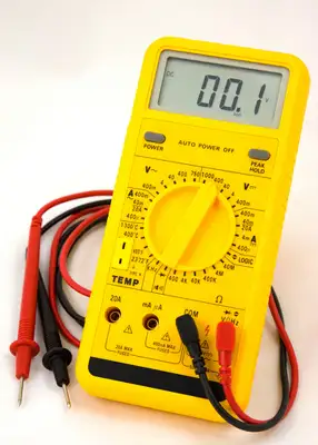
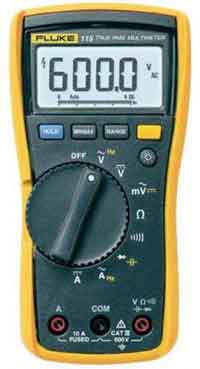
Digital multimeters, often called DMMs, display readings on a digital screen. They are widely used because they are easy to read and offer strong accuracy for most electrical measurements. Many include auto-ranging, data hold, and true RMS capability, which is important when dealing with modern electronic loads and non-sinusoidal AC waveforms.
Analog multimeters use a needle and scale to show values. While they are less precise than digital models, they can be useful for watching trends, fluctuations, or slow changes in a signal. Because the needle moves in real time, some technicians prefer them for tuning and troubleshooting intermittent problems.
Clamp multimeters measure current without breaking the circuit. By clamping around a single conductor, they sense the magnetic field generated by the current. This makes them especially valuable for measuring higher currents safely in maintenance, HVAC, and industrial environments.
Bench multimeters are designed for laboratories, calibration work, and research settings. They offer much higher resolution and accuracy than handheld models, but are not intended for field use. When comparing digital and analog devices, our guide to analog multimeters highlights how needle-based displays can still be useful for observing circuit trends.
Comparison of Multimeter Types
| Type | Accuracy | Features | Cost | Best For |
|---|---|---|---|---|
| Digital Handheld | High | Autoranging, RMS | Affordable | Everyday troubleshooting and field service |
| Analog | Moderate | Needle display | Low | Observing signal trends and teaching basics |
| Clamp Meter | High | Non-contact current | Moderate | Measuring high current safely in maintenance work |
| Bench Multimeter | Very High | High resolution | Expensive | Precision testing, R&D, and calibration labs |
Key Technical Concepts
Key Technical Concepts
Understanding a few core specifications helps explain how and why multimeters work reliably.
The input impedance is typically very high, often around 10 megohms. This prevents the meter from drawing current and altering the circuit being measured.
Accuracy and resolution define how close a reading is to the true value and how small a change the meter can detect. Handheld multimeters usually balance accuracy and durability, while bench meters prioritize precision.
True RMS capability enables the meter to measure complex AC waveforms accurately. This is increasingly important in systems that use variable-frequency drives, electronic power supplies, and non-linear loads.
Safety ratings, ranging from CAT I to CAT IV, indicate where a multimeter can be safely used. Higher categories are designed for higher-energy environments such as distribution panels or utility service entrances. Learning how to use a digital multimeter provides step-by-step instructions for safely measuring voltage, current, and resistance.
What You Can Measure With a Multimeter
A multimeter can do much more than basic voltage checks. Common measurement functions include AC and DC voltage, AC and DC current, resistance, and continuity. Many modern models also measure capacitance, frequency, and temperature, and include a diode test function for checking electronic components.
Because of this versatility, multimeters are often the first diagnostic step before more specialized instruments are used. Correct probe placement, range selection, and safety awareness are critical for reliable measurements.
To obtain accurate measurements when testing electrical components, it is essential to understand their electrical properties and use the instrument correctly. Before testing, set your multimeter to measure the appropriate function so voltage measurements reflect actual circuit conditions. Checking for voltage drop across conductors or connections can reveal high resistance due to loose terminals, corrosion, or failing components. Identifying these issues early helps prevent equipment damage, improves troubleshooting accuracy, and ensures electrical systems operate safely and efficiently.
Choosing the Right Multimeter
Selecting a multimeter depends on how and where it will be used. Occasional household testing may only require a basic digital model, while industrial work demands higher safety ratings and rugged construction. Features such as auto-ranging, backlighting, and data logging improve usability, especially in field conditions.
For technicians working around energized equipment, safety ratings and quality test leads are just as important as accuracy. Choosing the right tool helps protect both the user and the equipment being tested.
Applications and Practical Use
Multimeters are used across homes, factories, vehicles, and laboratories. They help identify blown fuses, confirm correct wiring, test batteries and power supplies, and verify control signals in industrial systems. In preventive maintenance programs, routine multimeter testing helps detect problems early and reduce downtime. In industrial settings, understanding what is a multimeter goes hand in hand with broader practices like industrial electrical maintenance, where accuracy and safety are critical.


Advantages and Limitations
The main strength of a multimeter is convenience. It combines multiple measuring functions into a single portable device, making it fast and practical for troubleshooting. However, it is not a replacement for high-precision laboratory instruments, and improper use can lead to inaccurate readings or damaged equipment. For preventive strategies, multimeters complement other tools covered in preventive maintenance training, ensuring equipment remains reliable and downtime is minimized.
Safety and Good Practice
Safe multimeter use depends on proper technique. Always verify the selected function and range before making a measurement. Use probes rated for the environment and follow established electrical safety practices. Regular inspection and calibration help maintain accuracy and reliability over time. Failure to follow safety precautions can lead to inaccurate readings, blown fuses, or electric shock. Standards such as NFPA 70B 2023 emphasize the importance of testing equipment, including multimeters, as part of a comprehensive electrical maintenance program.
History and Terminology
The term “multimeter” comes from its ability to measure multiple electrical quantities. Early versions were known as Volt-Ohm-Meters (VOMs) and relied on analog needle movement. Digital multimeters became widespread in the late twentieth century, bringing improved accuracy and ease of use while retaining the same core purpose.
A multimeter remains one of the most important diagnostic tools in electrical work. By understanding how it works, what it can measure, and how to use it safely, users gain a clearer picture of electrical systems and the confidence to troubleshoot them effectively. Because multimeters are often the first line of defence in electrical troubleshooting, they play a central role in diagnosing faults before moving on to more specialized instruments.
