How can I mark off arc flash boundaries?
By R.W. Hurst, Editor
By R.W. Hurst, Editor
Our customized live online or in‑person group training can be delivered to your staff at your location.
How can I mark off arc flash boundaries? Follow NFPA 70E and IEEE 1584, calculate incident energy, set approach limits, apply labels, post warning signs, and install barricades with required PPE distances.
To mark off an arc flash boundary, calculate the distance at which incident energy drops to 1.2 cal/cm² using NFPA 70E or IEEE 1584 formulas. Once calculated, physically mark the perimeter with signage, floor tape, or barriers to alert personnel of the restricted area. For a step-by-step example of applying these formulas, see our Arc Flash Boundary Calculation guide for practical setup tips.
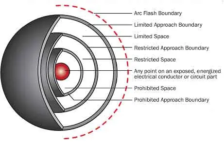
An arc flash boundary is a safety perimeter set around electrical equipment to protect individuals from the potential harm of an arc flash. The boundary is defined as the distance from the equipment where the energy released during an arc flash drops to 1.2 cal/cm², a level that can cause second-degree burns. Determining this boundary is a critical task typically performed by an electrical engineer. Here’s an overview of how these boundaries are calculated. A concise primer on key definitions is available in our Arc Flash Boundary overview to help teams align terminology.
Request a Free Training Quotation
The calculation of an arc flash boundary depends primarily on the voltage of the equipment involved. The calculation methods differ between AC and DC systems, so it is essential to have accurate system information.
Using Software for Calculation
Many companies utilize specialized software to calculate arc flash boundaries. These programs allow users to input voltage and other relevant data about the equipment. The software then processes this information to determine the arc flash boundary accurately, providing critical data for setting safety distances within a facility. If you're new to the inputs and assumptions these tools use, review Understanding Arc Flash Calculations to validate your model choices.
Download our FREE Electrical Training Catalog and explore a full range of expert-led electrical training courses.

Manual Calculation Methods
For businesses without access to such software or those seeking to verify results manually, there are two main methodologies for calculating the boundary. When comparing results, a quick check against a boundary table by incident energy can flag outliers.
NFPA 70E Formula: The NFPA 70E standard provides a formula to calculate the incident energy of equipment. This formula considers factors such as voltage, current, and distance to establish the arc flash boundary. For context on how this relates to shock protection thresholds, see how arc flash and electric shock protection boundaries are determined for integrated planning.
IEEE 1584 Formula: This method uses empirically-based formulas derived from extensive laboratory testing. IEEE 1584 is often regarded as more accurate due to its comprehensive data and refined calculations. You can visualize typical distances using an arc flash boundary chart to support field briefings.
Regardless of the method used—whether software or manual calculations—accuracy in input data is paramount. Incorrect voltage or system information will lead to inaccurate boundary determinations, putting employees and facilities at risk. Ensuring precise and verified data entry is crucial for establishing effective and reliable arc flash boundaries.
Establishing and adhering to arc flash boundaries is essential for workplace safety. These boundaries help to protect individuals from severe burns and other injuries caused by arc flashes. Properly determined boundaries also contribute to the overall safety protocol of a facility, ensuring that all personnel are aware of and respect the safe distances around electrical equipment. For foundational information on arc flash boundaries, visit our Arc Flash Boundary section.
Determining arc flash boundaries involves understanding the equipment's voltage, utilizing accurate calculation methods, and ensuring precise data entry. Whether through advanced software or manual calculations using NFPA 70E or IEEE 1584 formulas, the goal is to establish a safe perimeter that protects individuals from the dangers of arc flashes. For example scenarios, many practitioners reference the boundary for 8 cal/cm² when selecting PPE categories.
Stay informed with our FREE Arc Flash Newsletter — get the latest news, breakthrough technologies, and expert insights, delivered straight to your inbox.
Advantages To Instructor-Led Training – Instructor-Led Course, Customized Training, Multiple Locations, Economical, CEU Credits, Course Discounts.
Request For QuotationWhether you would prefer Live Online or In-Person instruction, our electrical training courses can be tailored to meet your company's specific requirements and delivered to your employees in one location or at various locations.