Electric Motor Design Engineering
By Robert Repas, Machine Design
Motor Control Training
Our customized live online or in‑person group training can be delivered to your staff at your location.
- Live Online
- 12 hours Instructor-led
- Group Training Available
Download Our OSHA 4474 Fact Sheet – Establishing Boundaries Around Arc Flash Hazards
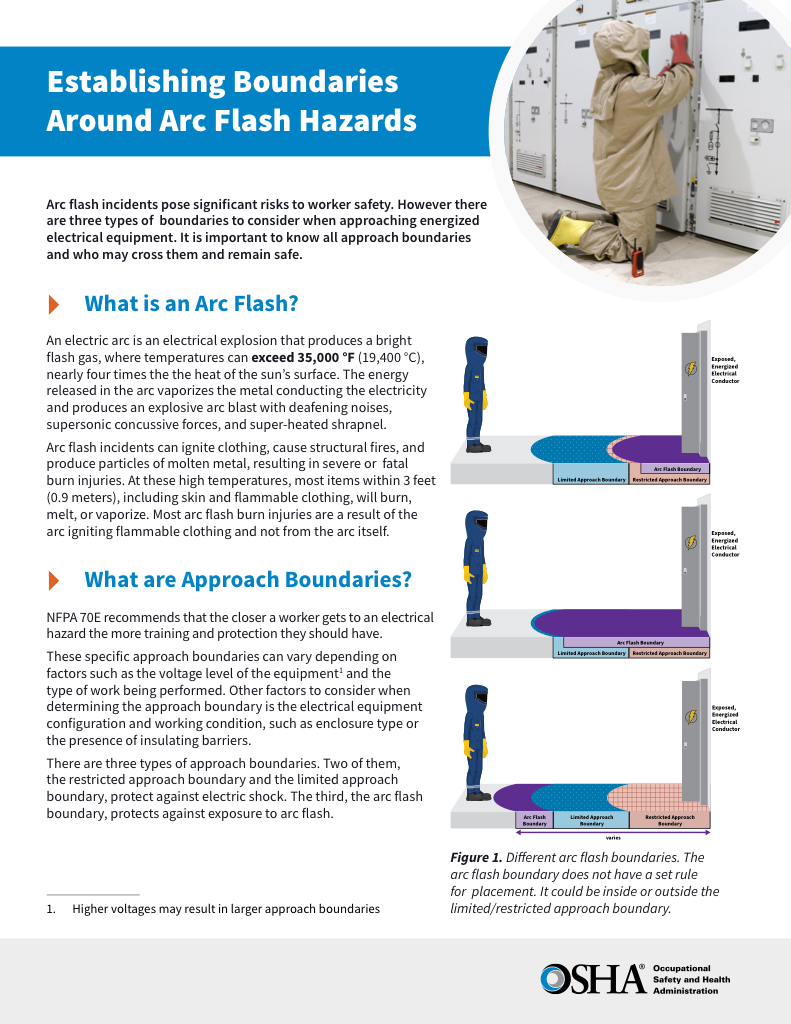
- Understand the difference between arc flash and electric shock boundaries
- Learn who may cross each boundary and under what conditions
- Apply voltage-based rules for safer approach distances
Electric motor design enhances efficiency, torque, and speed control by applying principles of electromagnetism. Optimized stator, rotor, and winding configurations deliver reliable performance, durability, and energy savings across industrial power applications.
What is Electric Motor Design?
Electric motor design is the engineering process of creating efficient, durable, and high-performance motors that convert electrical energy into mechanical motion.
✅ Balances electric motor efficiency, torque, and speed control
✅ Uses stator, rotor, and winding optimization
✅ Ensures reliability in industrial and consumer systems
Electric Motor Testing Training
Request a Free Training Quotation
Types of Electric Motors
Electric motors, including both AC motors and DC motors, come in a wide range of shapes and sizes. Some are standardized for general-purpose use, while others are tailored for specific applications. The main categories include:
-
AC Induction Motors – rugged, low-cost, and common in industrial applications.
-
Synchronous Motors – operate at constant speed with higher efficiency and power factor.
-
DC Motors – provide precise control but require brushes and commutators.
-
Brushless DC (BLDC) Motors – efficient, reliable, and widely used in EVs and appliances.
-
Stepper Motors – offer incremental motion for robotics and automation.
-
Linear Motors – produce direct linear motion without gears.
-
Switched Reluctance Motors – simple construction with high torque density, increasingly popular in EV design.
Each type involves trade-offs in cost, efficiency, control complexity, and application suitability.
Electric Motor Types Comparison
| Motor Type | Key Features | Advantages | Common Applications |
|---|---|---|---|
| AC Induction Motor | Rotor induced by stator field | Low cost, reliable, low maintenance | Pumps, fans, conveyors |
| Synchronous Motor | Rotor speed equals stator field speed | High efficiency, good power factor | Compressors, power correction |
| DC Motor | Uses brushes and commutators | Simple control of speed and torque | Cranes, hoists, rolling mills |
| Brushless DC (BLDC) | Permanent magnets, electronic drive | High efficiency, quiet, long life | EVs, appliances, robotics |
| Stepper Motor | Moves in discrete steps | Precise positioning, open-loop | CNC machines, 3D printers |
| Linear Motor | Produces linear motion | Direct motion, no gears required | Maglev trains, automation |
| Switched Reluctance | Reluctance torque, simple rotor | High torque density, robust design | EVs, aerospace, heavy drives |
Motor Selection Criteria
Regardless of type, motors should be selected to meet the dynamic requirements of the machine they drive without exceeding rated temperature. The first and most important step is determining load characteristics, specifically, torque and speed as a function of time. Motor selection also depends on mission goals, available power, and cost, as well as proper motor overload protection.
Torque and Acceleration
Starting and running torque are crucial in determining the size of motors. Requirements can vary from a fraction of full load to several times the rated torque. Variations occur due to load conditions or machine characteristics, such as lubrication or wear. The motor’s supplied torque must always exceed that required from start to full speed. Greater reserve torque allows faster acceleration.
Test Your Knowledge About Motors and Drives!
Think you know Motors and Drives? Take our quick, interactive quiz and test your knowledge in minutes.
- Instantly see your results and score
- Identify strengths and areas for improvement
- Challenge yourself on real-world electrical topics
When gear reducers are involved, rotating parts move at different speeds. To calculate the required acceleration torque, all component inertias must be reduced to a common reference point, typically at the drive shaft.
Electric Motor Power Rating
Electric motors provide the horsepower necessary to drive a machine. The common equation is:
hp = (torque × rpm) / 5,250
For variable loads, a horsepower vs. time curve helps determine both peak and RMS values. RMS load horsepower defines the continuous rating, while peak load horsepower indicates short-term capacity. If a peak is sustained, the motor rating must at least equal that load.
Duty Cycle
Loads vary widely across applications. Fans and blowers operate continuously, while compressors or pumps may start and stop frequently. Some machine tools cycle many times per minute. Duty cycle—the ratio of on-time to total cycle time—becomes a crucial factor when motors idle or operate at reduced load for extended periods. Effective electric motor maintenance helps manage these stresses and extend equipment life.
Frequent starting consumes far more energy than steady operation, risking overheating. At a constant speed, torque is directly proportional to horsepower; however, during acceleration or overloads, equivalent horsepower is used. Examining motor performance curves helps ensure sufficient torque for friction, acceleration, and overload conditions.
Service Factors
NEMA standards define motor service factors and allowable temperature rise. A service factor above unity indicates a motor can be overloaded without overheating. For example, Class-B insulated motors with service factors of 1.15 and 1.25 are rated for the same 90°C rise; however, the higher service factor motor must be larger to dissipate the extra heat.
Service factors account for occasional overloads, undefined service conditions, or cooler-than-normal operation, thereby extending insulation life.
Materials and Magnetic Core Design
Magnetic materials play a critical role in performance. Laminated steel reduces eddy current losses, while silicon steel and soft magnetic alloys improve efficiency. Permanent magnets enhance torque density in BLDC and synchronous machines; however, cost and supply chain issues, particularly with rare-earth magnets, must be considered. Rotor slot shapes, bar configurations, and stator lamination geometry also influence torque ripple, efficiency, and manufacturability.
Loss Analysis and Efficiency Trade-Offs
Motor efficiency depends on minimizing losses:
-
Copper Losses – resistance heating in windings.
-
Iron Losses – hysteresis and eddy currents in the core.
-
Mechanical Losses – friction and windage in bearings and fans.
-
Stray Losses – leakage flux and harmonics.
Designers balance conductor size, lamination thickness, cooling, and material choice against cost, weight, and efficiency targets. Increasing copper content lowers resistance but increases cost and weight. Thin laminations cut eddy losses but complicate manufacturing.
Thermal and Cooling System Design
Heat management is vital. Motors use insulation systems rated by class, ensuring windings and cores remain within safe limits. Cooling methods include:
-
Natural air cooling – simple and low-cost.
-
Forced air cooling – fans to move heat away.
-
Liquid cooling – for high-density applications like EVs.
Thermal runaway can damage insulation and reduce motor life, so accurate thermal modeling is essential.
Simulation, Modeling, and Design Tools
Modern motor design relies on advanced tools:
-
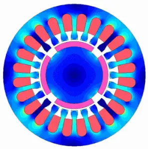
Finite Element Analysis (FEA) for electromagnetic fields.
-
Computational Fluid Dynamics (CFD) for cooling airflow.
-
Multiphysics Simulation to couple electrical, thermal, and structural performance.
These tools predict losses, optimize designs, and shorten development cycles.
Standards, Nameplate Data, and Compliance
International standards (NEMA, IEC) define performance, efficiency, and safety. Nameplate data typically includes horsepower, voltage, current, efficiency class, duty cycle, power factor, and frame size. Engineers use this information to verify the suitability of the system for specific loads and ensure compliance with efficiency regulations.
FREE EF Electrical Training Catalog
Download our FREE Electrical Training Catalog and explore a full range of expert-led electrical training courses.

- Live online and in-person courses available
- Real-time instruction with Q&A from industry experts
- Flexible scheduling for your convenience
Application-Specific Constraints
Motor design adapts to industry needs:
-
EVs – demand high torque, high efficiency, and compact size.
-
Aerospace – requires lightweight, fault-tolerant motors.
-
Industrial equipment – emphasizes durability and reliability.
Environmental considerations include noise, vibration, and cooling requirements. Cost factors, availability of rare earth materials, and manufacturability also shape design choices. In many cases, variable frequency drives are applied to optimize energy efficiency and improve control.
Design Geometry Considerations
Air gap size directly influences efficiency and torque production. Rotor and stator geometry, winding type (distributed or concentrated), and number of poles affect torque ripple, harmonic distortion, and manufacturability. Small changes in geometry can improve performance, but may also increase costs.
Cost and Manufacturability
A practical motor must strike a balance between performance and economic feasibility. Design decisions consider:
-
Material costs and availability.
-
Ease of winding and insulation.
-
Tolerance requirements for laminations and machining.
-
Overall manufacturability at scale.
Trade-offs between cost and performance guide final design choices.
Electric motor design is a complex balance of electromagnetic theory, materials science, thermal management, standards, and application needs. By addressing torque, power, duty cycle, losses, cooling, and manufacturability, engineers design reliable and efficient motors tailored to meet the demands of modern industrial, commercial, and consumer applications. Learn more in our Electric Motors and Drives guide.
From: Electric Motors and VFDs Handbook, Vol. 3, The Electricity Forum


