What is an Arc Fault?

By R.W. Hurst, Editor


what is an arc fault

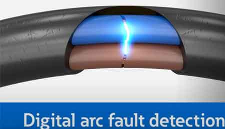
An arc fault is a dangerous electrical discharge between conductors or to ground. It generates intense heat and light, often caused by damaged insulation, frayed wires, or loose connections, posing major electrical safety and fire hazards.


What is an Arc Fault?

An arc fault is an unintended electrical discharge that occurs when insulation or wiring fails, producing dangerous heat that can ignite fires and damage circuits.

✅ Caused by frayed wires or loose connections

✅ Produces intense heat and light energy

✅ Prevented by Arc Fault Circuit Interrupters (AFCIs)


Basic Protection Relay Training

Short Circuit Study Training

Request a Free Training Quotation


Understanding Arc Faults and Electrical Safety

An arc fault is a hazardous electrical event that can lead to severe consequences, including fires and substantial property damage. Understanding how faults occur, how to prevent them, and why protective measures like Arc Fault Circuit Interrupters (AFCIs) are essential can significantly improve home and workplace safety.

When electrical current jumps across a gap or an unintended path, it forms an electric arc. This arc generates extremely high temperatures—often exceeding 10,000°F—capable of igniting nearby insulation, wood framing, or other combustible materials. Faults are typically caused by damaged, frayed, or aging wiring, loose terminal connections, or punctured cables from nails and screws during construction. For more insight into advanced safety devices, learn how an arc fault interrupter breaker detects hazardous arcing and disconnects power before a fire can start.

Arc fault protection is especially important in areas where people live and spend time, such as family rooms, dining rooms, and living rooms, where electrical wiring runs behind walls containing materials such as wood framing or insulation that can easily ignite. Modern safety standards, as mandated by the National Electrical Code, require the installation of Arc Fault Circuit Interrupters (AFCIs) in these spaces to prevent fires caused by faults. When combined with Ground Fault Circuit Interrupters, which protect against electrical shock, AFCIs provide comprehensive protection against both fire and shock hazards in residential and commercial environments.


Types of Arc Faults

Arc faults can appear in different forms, each with its own risks and detection requirements:

  • Series Faults – Occur along a single conductor, usually from a broken wire or loose terminal. These arcs produce less current but can still ignite fires.

  • Parallel Faults – Form between two conductors (hot-to-neutral or hot-to-ground). These faults create higher current levels and more intense arcing.

  • Ground Faults – Happen when current leaks or shorts to a grounded surface, such as a metal outlet box or appliance casing. Explore how ground fault protection complements AFCIs by guarding against current leakage that could cause electric shock or parallel arc conditions.

Recognizing these types helps electricians and inspectors identify the right protection strategies and select appropriate AFCI devices. To see how fault current behavior impacts fault risks, review our explanation of available fault current and why accurate short-circuit studies are essential for system safety.


How AFCI Detection Works

AFCIs are intelligent safety devices designed to detect the unique electrical signatures of faults. They continuously monitor current waveforms and frequencies, distinguishing dangerous arcs from normal switching arcs (such as those produced by light switches or vacuum cleaners).

When an AFCI identifies an abnormal frequency pattern consistent with arcing, it trips the circuit within milliseconds—disconnecting power before the fault can ignite a fire. This advanced “signature detection” technology is required by modern safety codes and has saved countless lives and properties. For more insight into advanced safety devices, learn how an arc fault interrupter breaker detects hazardous arcing and disconnects power before a fire can start.


Limitations and Nuisance Tripping

While AFCIs are highly effective, they can occasionally cause nuisance tripping. This occurs when the device misinterprets harmless electrical noise as a fault, typically triggered by motors, dimmers, or other electronic devices. Regular inspection, proper grounding, and updated AFCI models help minimize these false positives. If nuisance tripping persists, it’s advisable to have an electrician verify circuit wiring and device compatibility. To understand how electrical systems respond to fault conditions, refer to our detailed explanation of protective relay coordination, which ensures that circuit breakers isolate faults without disrupting unaffected circuits.


Code Requirements and Standards

Arc fault protection is mandated by both U.S. and Canadian electrical codes:

  • National Electrical Code (NEC 210.12) requires AFCI protection for all 120-volt, single-phase, 15- and 20-amp branch circuits supplying living areas such as bedrooms, family rooms, dining rooms, and similar spaces.

  • Canadian Electrical Code (CEC Section 26) similarly mandates AFCI in dwelling units.

  • IEEE 1584 provides calculation guidelines for flash hazards in industrial power systems, complementing residential and commercial fault safety standards.

Following these standards ensures compliance and dramatically reduces fire risks across residential, commercial, and industrial applications.


Statistics and Case Studies

According to the U.S. Consumer Product Safety Commission (CPSC), electrical fires cause over 51,000 residential fires annually, resulting in more than 500 deaths and $1.3 billion in property damage. Studies show that AFCI protection can prevent more than half of these incidents, highlighting its critical role in modern electrical safety systems.


Emerging Technologies in Arc Fault Detection

New generations of AFCIs utilize microprocessors and artificial intelligence to enhance accuracy and minimize false trips. These smart devices analyze waveform patterns with greater precision, detecting high-impedance arcs and subtle irregularities. Future technologies may integrate predictive analytics and IoT monitoring to diagnose potential faults before they become hazards. Finally, explore comprehensive methods of electrical surge protection, which safeguard sensitive equipment from voltage spikes often linked to lightning events.


Common Causes of Arc Faults

  • Damaged or aging electrical wiring

  • Loose terminal connections in outlets or switches

  • Overloaded circuits or faulty appliances

  • Nails or screws penetrating electrical cables

  • Deteriorated insulation from heat, moisture, or rodents

Regular maintenance and periodic inspections by a licensed electrician are essential preventive measures.


Arc Fault vs Ground Fault vs Short Circuit

Fault Type Description Main Hazard Protection Device
Arc Fault Unintended arcing between conductors or within wiring Fire risk AFCI
Ground Fault Current flowing to ground unintentionally Electric shock GFCI
Short Circuit Direct contact between conductors High current / equipment damage Circuit Breaker

Understanding these differences helps ensure that electrical protection systems are properly matched to the specific hazards they are intended to address.


Frequently Asked Questions


Why does my AFCI keep tripping?

Often due to electronic interference, shared neutrals, or actual wiring issues. Replace outdated AFCIs and consult a professional if tripping persists.


Can I retrofit AFCIs into older panels?

Yes. AFCI breakers can replace standard breakers in most modern panels. Have a qualified electrician confirm compatibility before installation.


Are AFCIs required everywhere?

While required in most living spaces, some regions exempt areas like garages or unfinished basements. Check the NEC or CEC requirements for your jurisdiction.


Related Articles


Related News

What is an Electrical Circuit?

An electrical circuit is a closed loop that allows electric current to flow through conductors, power sources, and loads. Circuits connect electrical devices, enable energy transfer, and ensure safe operation in homes, industries, and power systems.


What is an Electrical Circuit?

An electrical circuit is a path through which electricity flows from a power source to one or more devices that are connected.

✅ Provides controlled current flow through conductors

✅ Powers electrical devices safely and efficiently

✅ Includes sources, loads, and protective components

Gaining a grasp of the basic electricity of electrical circuits, including series and parallel configurations, voltage, current, resistance, Ohm's Law, and circuit analysis techniques, is vital for anyone interested in electronics, electrical engineering, or the inner workings of modern technology.


Core Components & Function

In order to understand what an electrical circuit is, one must appreciate that, 

At its core, an electrical circuit is a closed loop or pathway that facilitates the flow of electric current. This concept is essential in electronics and electrical engineering, as it provides the basis for the operation of everyday items, including smartphones, computers, and home appliances.

Within an electrical circuit, components are connected via conductive materials, such as wires, which enable the movement of electrons from a power source to other components and back.

The primary components of an electrical circuit include a power source (e.g., a battery or power supply unit), conductive materials (typically wires), a load (such as a resistor, motor, or light bulb), and a control element (for example, a switch). The power source supplies the voltage necessary for electric current flow, while the load transforms electrical energy into other forms, such as light or heat. Meanwhile, the control element permits the user to initiate or halt the flow of electrons, effectively turning a device on or off.

  • For students, a simple example is a battery connected to an LED, which demonstrates how electricity creates light.

  • For professionals, an industrial motor powered by a control circuit shows how electrical energy drives large-scale equipment.


Circuit Types (Series vs. Parallel)

Electrical circuits can be classified into three main types: series, parallel, and combination circuits.

  • Series circuits connect components end-to-end, allowing current to flow sequentially through each one. Example: holiday string lights, where a single bulb outage can disrupt the entire circuit.

  • Parallel circuits enable current to flow through multiple paths. Example: household wiring, where turning off one light doesn’t affect others.

  • Combination circuits mix both series and parallel configurations to handle more complex systems.


Fundamental Laws (Ohm’s Law, Kirchhoff’s Laws)

A fundamental understanding of voltage, current, and resistance is crucial for comprehending electrical circuit operations.

Voltage, the driving force that propels electric charge through a circuit, and current, the flow of electric charge measured in amperes (A), are closely related to resistance. Resistance, expressed in ohms (Ω), represents the opposition to the flow of current. These elements are interconnected through Ohm's law, which states that the voltage across a conductor is directly proportional to the current it carries and inversely proportional to its resistance: V = IR, where V represents voltage, I denotes current, and R represents resistance. Understanding how current creates magnetic fields is explained by Ampere's Law, which forms the basis for analyzing electromagnetism in electrical circuits.

Circuit analysis determines the current, voltage, and power associated with each component in an electrical circuit. Techniques such as Kirchhoff's Law of voltage and current, Thevenin's theorem, and Norton's theorem are employed to analyze and resolve electrical circuit issues. These methods enable engineers to design and troubleshoot electronic devices and systems effectively.


Thevenin's Theorem

Thevenin's theorem is a fundamental principle in electrical engineering and circuit analysis. It is a powerful technique to simplify complex linear circuits, making it easier to analyze and calculate the current, voltage, and power across specific components. The theorem is named after the French engineer Charles Léonard Siméon Thévenin, who proposed it in 1883.


Thevenin's theorem states that any linear, active, bilateral network containing voltage sources, current sources, and resistors can be replaced by an equivalent circuit consisting of a single voltage source (called Thevenin's voltage, Vth) in series with a single resistor (called Thevenin's resistance, Rth) connected to the terminals of the original circuit. This simplified circuit, known as the Thevenin equivalent circuit, can then be used to analyze the behaviour of the original circuit with a specific load connected to its terminals.

Steps to apply Thevenin’s theorem:

  1. Identify the portion of the circuit you want to simplify and the terminals where the load will be connected.

  2. Remove the load from the terminals (if present) and leave the terminals open-circuited.

  3. Calculate the open-circuit voltage across the terminals. This value is Thevenin's voltage (Vth).

  4. Calculate the equivalent resistance seen from the open-circuited terminals with all independent voltage sources replaced by short circuits (zero resistance) and all independent current sources replaced by open circuits (infinite resistance). This value is Thevenin's resistance (Rth).

  5. Create the Thevenin equivalent circuit using the calculated Vth and Rth values, then connect the original load across the terminals.

Once the Thevenin equivalent circuit is determined, you can easily analyze the circuit's behaviour and calculate the current through the load, the voltage across the load, or even the power delivered to the load. This technique is particularly useful when analyzing circuits with varying loads or examining the circuit's behaviour at multiple points, as it simplifies calculations and saves time.


Norton’s Theorem

Norton's theorem is a fundamental principle in electrical engineering and circuit analysis that simplifies the analysis of complex linear circuits. Named after the American engineer Edward Lawry Norton, who introduced it in the early 20th century, the theorem is a counterpart to Thevenin's theorem.


While Thevenin's theorem reduces a complex network to an equivalent voltage source in series with a resistor, Norton's theorem simplifies the network to an equivalent current source parallel to a resistor.

Norton's theorem states that any linear, active, bilateral network containing voltage sources, current sources, and resistors can be replaced by an equivalent circuit consisting of a single current source (called Norton's current, IN) in parallel with a single resistor (called Norton's resistance, RN) connected to the terminals of the original circuit.

Steps to apply Norton’s theorem:

  1. Identify the portion of the circuit you want to simplify and the terminals where the load will be connected.

  2. Remove the load from the terminals (if present) and leave the terminals open-circuited.

  3. Calculate the short-circuit current flowing between the terminals. This value is Norton's current (IN).

  4. Calculate the equivalent resistance seen from the open-circuited terminals with all independent voltage sources replaced by short circuits (zero resistance) and all independent current sources replaced by open circuits (infinite resistance). This value is Norton's resistance (RN). Note that Norton's resistance is equal to Thevenin's, as both are calculated similarly.

  5. Create the Norton equivalent circuit with the calculated IN and RN values, connecting the original load across the terminals.

Once the Norton equivalent circuit is established, you can easily analyze the circuit's behaviour and calculate the current through the load, the voltage across the load, or even the power delivered to the load. Like Thevenin's theorem, Norton's theorem is particularly useful when dealing with varying loads or analyzing a circuit's behaviour at multiple points. In addition, it simplifies calculations, conserving time and effort.


Circuit Diagrams & Symbols

Circuit diagrams, also known as schematic diagrams, are graphical representations of electrical circuits that utilize standardized symbols to depict components such as resistors, capacitors, inductors, diodes, and transistors. These symbols facilitate the interpretation of a circuit's structure and function by engineers or hobbyists without requiring physical examination of the actual components.

Here are some common symbols used in circuit diagrams:

Resistor: A simple zigzag line represents a resistor, which opposes the flow of electric current and dissipates energy in the form of heat.

Capacitor: Two parallel lines with a small gap represent a capacitor. The positive plate is marked with a "+" sign in polarized capacitors, and a curved line represents the negative plate.

Inductor: A series of curved or looped lines, similar to a coil, represents an inductor, which stores energy in a magnetic field and opposes changes in current.

Diode: A triangle pointing to a line represents a diode, which allows current to flow in one direction but blocks it in the opposite direction.

Light-emitting diode (LED): Similar to a diode symbol, but with two arrows pointing away from the triangle, representing light emission.

Transistor: Two types of transistors are commonly used: bipolar junction transistors (BJTs) and field-effect transistors (FETs). A BJT symbol comprises a circle or rectangle with three connected leads (emitter, base, and collector). FET symbols are represented by a combination of lines and a vertical arrow with three terminals (gate, source, and drain).

Integrated circuit (IC): A rectangular or square box with multiple leads connected represents an integrated circuit, a complex assembly of numerous electronic components within a single package.

Battery: Alternating long and short parallel lines represent a battery, a source of electrical energy.

Power supply: A circle with an arrow pointing upwards or a combination of letters, such as "Vcc" or "+V," represents a power supply, which provides a constant voltage or current.

Switch: A break in line with an angled line nearby or a pair of lines connected by a diagonal line represents a switch, which controls the flow of current by making or breaking a circuit.

Ground: A series of horizontal lines that decrease in length, a downward-pointing arrow, or the letters "GND" represent a ground connection, which serves as a reference point and provides a return path for electrical currents.

These are just a few examples of the many symbols used in circuit diagrams. Therefore, it's essential to familiarize yourself with these symbols to read or create schematic diagrams for electrical or electronic circuits. The ability of a circuit to store electrical charge is described by Capacitance, a key principle in both electronics and power systems.


Practical Applications & Examples

Electrical circuits form the foundation of modern technology, enabling us to harness electricity to operate a wide range of devices and systems. From smartphones and computers to household appliances and industrial machines, circuits power nearly every aspect of daily life.

For example, a simple battery connected to a light bulb demonstrates how a closed loop allows current to flow, converting electrical energy into light and heat. Safe return paths for current are established through the proper installation of Grounding Electrode Conductors, which helps prevent shock and equipment damage.


Frequently Asked Questions


What is the simplest electrical circuit?

The simplest circuit consists of a power source (such as a battery), a conductor (like a wire), and a load (like a bulb). Closing the loop lets current flow and power the load.


How do series and parallel circuits differ in real life?

Series circuits share a single path, so if one component fails, the entire circuit stops. Parallel circuits have multiple paths, allowing devices to operate independently.


Why is grounding important in electrical circuits?

Grounding provides a safe return path for electricity. It reduces shock hazards and prevents equipment damage during faults or surges.


What role does resistance play in a circuit?

Resistance controls the amount of current flowing. High resistance limits current, while low resistance allows more current to pass.


What is the function of a circuit breaker or fuse?

These protective devices interrupt the current when it becomes too high, preventing overheating, fires, and damage to equipment. To safeguard devices and wiring from excessive currents, engineers rely on Overcurrent Protection Device such as fuses and circuit breakers.


What is an electrical circuit? Why It Matters

Electrical circuits are the backbone of modern technology, powering everything from smartphones and appliances to industrial systems. A firm grasp of fundamental circuit principles is crucial for engineers, electricians, and hobbyists, as it unlocks a deeper understanding of the devices that shape everyday life.


Related Articles


View more

What is Capacitance?

Capacitance is the ability of a component to store electrical charge between plates separated by insulation, measured in farads. It is vital in circuits, electronics, and energy storage for voltage regulation, stability, and efficient power system performance.


What is Capacitance?

Capacitance is a fundamental concept in electrical engineering and physics, describing a system's ability to store energy in the form of an electrical charge.

✅ Measures the ability to store electric charge in a circuit

✅ Essential in filtering, timing, and power conditioning

✅ Found in capacitors used in electronics, motors, and power supplies

Capacitance (C = Q / V) measures the amount of electric charge (Q) a system stores per volt (V); unit: farad (F).

Power Quality Analysis Training

Power Factor Training

Request a Free Power Quality Training Quotation

Capacitance is the property of a system that allows it to store electric charge when a voltage, or electric potential difference, is applied across its terminals. This stored charge represents the system’s charge storage capacity, which is directly proportional to the capacitance value and the applied voltage. In alternating current (AC) circuits, capacitors do not pass current in the same way resistors do; instead, they oppose changes in voltage through a phenomenon known as capacitive reactance. This reactance decreases as the frequency of the AC signal increases, making capacitors essential in filtering, tuning, and timing applications. To understand how stored charge behaves across voltage differences, refer to our guide on capacitive load, which explores how capacitors affect AC circuits. For a detailed breakdown of how capacitance is measured, check out the unit of capacitance to understand farads and their practical conversions.


What Determines Capacitance?

The capacitance of a capacitor is determined by its geometry and the properties of the dielectric material between the conductive plates. The unit of capacitance is the farad, which can be measured in farads. Capacitors are often rated in microfarads (μF) or picofarads (pF), depending on their size and intended use.  For the basics of components that store electrical energy, see what is a capacitor to learn how these devices function and their role in circuits.

Learn how stored charge relates to apparent and real power in AC systems by visiting our apparent power vs real power comparison.

When a capacitor is connected to a voltage source, it charges, storing energy as an electrical field between its conductive plates. The amount of energy stored in a capacitor is proportional to its capacitance and the square of the voltage across it. When the voltage source is removed, the capacitor will slowly discharge, releasing the stored energy as an electrical current. Capacitance is also central to power factor optimization—discover how this works with an automatic power factor controller.


RC Circuits: The Role of Capacitance in Charging

A capacitor's charging and discharging behaviour is determined by its capacitance and the properties of the surrounding circuit. For example, in a simple circuit with a resistor and a capacitor, the capacitor will charge up rapidly when first connected to a voltage source. Still, it will then discharge slowly over time as the energy stored in the capacitor is dissipated through the resistor. The time constant of the circuit, which describes the rate at which the capacitor charges and discharges, is determined by the product of the resistance and capacitance of the circuit.

Capacitors are used in various electronic applications, from filtering noise in power supplies to storing energy in flash memory. The capacitance of a capacitor can be tuned by selecting different dielectric materials, changing the geometry of the conductive plates, or adding additional plates in parallel. To explore how capacitors behave when connected end-to-end, visit capacitance in series, which explains the reciprocal formula and voltage behavior.


Dielectric Materials and Their Effect on Capacitance

Dielectric materials are crucial to the operation of capacitors, as they serve as insulators between the conductive plates. The dielectric constant of a material describes its ability to store electrical energy and is a key parameter in determining the capacitance of a capacitor. Dielectric materials can be solid, such as ceramics or plastics, or liquid, such as electrolytes.

Capacitors can store energy in various forms, from high-voltage electrical energy in power supplies to low-voltage electrical energy in portable electronic devices. The energy stored in a capacitor can provide a quick burst of power to a circuit or smooth out variations in a power supply. If you're curious about how capacitors add their values in parallel, the capacitance in parallel page illustrates how capacitances sum directly, enhancing energy storage.


How Capacitance Compares to Resistance and Inductance

Resistance slows down the transfer rate of charge carriers (usually electrons) by "brute force." In this process, some energy is invariably converted from electrical form to heat. Resistance is said to consume power for this reason. Resistance is pre­sent in DC as well as in AC circuits and works the same way for either direct or alternat­ing current. Capacitor performance depends on safe voltage levels; our page on capacitor voltage rating explains these limits in detail.

Inductance impedes the flow of AC charge carriers by temporarily storing the en­ergy as a magnetic field. However, this energy is eventually replenished. For high-capacitance setups in electrical systems, see how banks of capacitors are configured in our capacitor bank overview.

Capacitance impedes the flow of AC charge carriers by temporarily storing the energy as an electric potential field. This energy is given back later, just as it is in an inductor. Capacitance is not generally necessary in pure-DC cir­cuits. However, it can have significance in circuits where DC is pulsating and not steady. If you're studying how capacitance affects reactive energy, visit our breakdown of reactive power formula in electrical circuits.


Capacitance in AC Circuits and Frequency Response

Capacitance, like inductance, can appear unexpectedly or unintentionally. As with inductance, this effect becomes more evident as the ac frequency increases.

Capacitance in electric circuits is deliberately introduced by a device called a capacitor. It was discovered by the Prussian scientist Ewald Georg von Kleist in 1745 and independently by the Dutch physicist Pieter van Musschenbroek at about the same time while investigating electrostatic phenomena. They discovered that electricity generated by an electrostatic machine could be stored for a period and then released. The device, which came to be known as the Leyden jar, consisted of a stoppered glass vial or jar filled with water, with a nail piercing the stopper and dipping into the water. By holding the jar in hand and touching the nail to the conductor of an electrostatic machine, they found that a shock could be obtained from the nail after disconnecting it by touching it with the free hand.

This reaction showed that some of the electricity from the machine had been stored. A simple but fundamental step in the evolution of the capacitor was taken by the English astronomer John Bevis in 1747 when he replaced the water with metal foil, forming a lining on the inside surface of the glass and another covering the outside surface. The interaction of capacitance and system reactance is a key part of understanding power quality, as explained on our reactor reactance in power systems page.


A Visual Thought Experiment: Capacitance Between Metal Plates

Imagine two very large, flat sheets of metal, such as copper or aluminum, that are ex­cellent electrical conductors. Suppose they are each the size of the state of Nebraska and are placed one on top of the other, separated by just a foot of space. What will happen if these two sheets of metal are connected to the terminals of a battery, as shown in Fig. 11-1?


Fig. 11-1. Two plates will become charged electrically, one positively and the other nega­tively.


The two plates will become charged electrically, one positively and the other nega­tively. You might think this would take a little while because the sheets are so big. However, this is a reasonable assumption.

If the plates were small, they would both become charged almost instantly, attaining a relative voltage equal to the battery's voltage. But because the plates are gigantic, it will take a while for the negative one to "fill up" with electrons, and it will take an equal amount of time for the other one to get electrons "sucked out." Finally, however, the volt­age between the two plates will be equal to the battery voltage, and an electric field will exist in the space between the plates.

This electric field will be small at first; the plates don't charge immediately. However, the negative charge and the positive charge will increase over time, depending on the size of the plates and the distance between them. Figure 11-2 is a relative graph showing the in­tensity of the electric field between the plates as a function of time elapsed since the plates are connected to the battery terminals.


Fig. 11-2. Relative electric field intensity, as a function of time, between two metal plates connected to a voltage source. 


Related Articles


View more

Electricity How it Works

Electricity How It Works explains electron flow, voltage, current, resistance, and power in circuits, from generation to distribution, covering AC/DC systems, Ohm's law, conductors, semiconductors, transformers, and energy conversion efficiency and safety.


What Is Electricity How It Works?

Explains electron flow, voltage, current, resistance, and power conversion in AC/DC circuits and key components.

✅ Voltage drives current through resistance per Ohm's law (V=IR).

✅ AC/DC systems distribute power via transformers and rectifiers.

✅ Conductors, semiconductors, capacitors, inductors shape circuits.


Electricity How It Works - This is a very common question. It can best be explained by stating this way: Single-phase electricity is what you have in your house. You generally talk about household electrical service as single-phase, 120-volt AC service. If you use an oscilloscope and look at the power found at a normal wall-plate outlet in your house, what you will find is that the power at the wall plate looks like a sine wave, and that wave oscillates between -170 volts and 170 volts (the peaks are indeed at 170 volts; it is the effective (rms) voltage that is 120 volts). The rate of oscillation for the sine wave is 60 cycles per second. Oscillating power like this is generally referred to as AC, or alternating current. The alternative to AC is DC, or direct current. Batteries produce DC: A steady stream of electrons flows in one direction only, from the negative to the positive terminal of the battery.

For a refresher on fundamentals, the overview at what is electricity explains charge, current, and voltage in practical terms.

AC has at least three advantages over DC in an electricity power distribution grid:

1. Large electricity generators happen to generate AC naturally, so conversion to DC would involve an extra step.
2. Electrical Transformers must have alternating current to operate, and we will see that the power distribution grid depends on transformers. 
3. It is easy to convert AC to DC but expensive to convert DC to AC, so if you were going to pick one or the other AC would be the better choice.

To connect these advantages to real-world practice, the primer on basic electricity clarifies AC versus DC behavior, impedance, and safety basics.

The electricity generating plant, therefore, produces AC. For a deeper look at how rotating machines induce AC, see the overview of electricity generators and their role in utility-scale plants.


Electricity How it Works in The Power Plant: Three-phase Power

If you want a quick walkthrough from generation to loads, this guide on how electricity works ties the concepts together before we examine three-phase specifics.

The power plant produces three different phases of AC power simultaneously, and the three phases are offset 120 degrees from each other. There are four wires coming out of every power plant: the three phases plus a neutral or ground common to all three. If you were to look at the three phases on a graph, they would look like this relative to ground:

A concise visual explainer on three-phase electricity shows how 120-degree phase offsets create balanced currents in feeders.

Electricity How It Works - There is nothing magical about three-phase power. It is simply three single phases synchronized and offset by 120 degrees. For wiring diagrams and common configurations, explore 3-phase power examples used across industrial facilities.

Why three phases? Why not one or two or four? In 1-phase and 2-phase electricity, there are 120 moments per second when a sine wave is crossing zero volts. In 3-phase power, at any given moment one of the three phases is nearing a peak. High-power 3-phase motors (used in industrial applications) and things like 3-phase welding equipment therefore have even power output. Four phases would not significantly improve things but would add a fourth wire, so 3-phase is the natural settling point.

Practical comparisons of motor torque ripple and line loading in 3-phase electricity help illustrate why three conductors strike the best balance.

And what about this "ground," as mentioned above? The power company essentially uses the earth as one of the wires in the electricity system. The earth is a pretty good conductor and it is huge, so it makes a good return path for electrons. (Car manufacturers do something similar; they use the metal body of the car as one of the wires in the car's electrical system and attach the negative pole of the battery to the car's body.) "Ground" in the power distribution grid is literally "the ground" that's all around you when you are walking outside. It is the dirt, rocks, groundwater, etc., of the earth.


Related Articles

View more

What is a Capacitor?

A capacitor is an electrical component that stores and releases energy in a circuit. It consists of two conductive plates separated by an insulator and is commonly used for filtering, power conditioning, and energy storage in electronic and electrical systems.


What is a Capacitor?

A capacitor is a key component in electronics and power systems. It temporarily stores electrical energy and is widely used in both AC and DC circuits.

✅ Stores and discharges electrical energy efficiently

✅ Used in filtering, timing, and power factor correction

✅ Found in electronics, motors, and power supplies

It is designed for energy storage and can store electric charges, which can be released when needed. In this article, we will delve into the fundamentals of capacitors, including their functions, types, and applications. To better understand how capacitors support overall system performance, explore our Power Quality overview covering the fundamentals of voltage stability and energy flow.

Power Quality Analysis Training

Power Factor Training

Request a Free Power Quality Training Quotation

A capacitor consists of two metallic plates separated by an insulating material known as the dielectric. The dielectric can be made from various materials, such as mica, paper, or ceramic. When voltage is applied across the plates, positive charges accumulate on one plate, while negative charges accumulate on the opposite plate. The amount of capacitor charge that can be stored depends on several factors, including plate area, plate separation, dielectric material, and voltage ratings. Capacitors are often used in capacitor banks to improve power factor and reduce energy losses in electrical systems.

How does a capacitor work? The primary function of a capacitor in an electronic circuit is to store electrical energy. Capacitors can be used for various purposes, such as filtering, timing, and coupling or decoupling signals. In addition, they play a crucial role in power supplies, ensuring that the output voltage remains stable even when there are fluctuations in the input voltage. Learn how capacitive loads influence circuit behavior and why they require precise capacitor selection for optimal performance.

A capacitor stores energy through the electrostatic field created between its plates. The stored energy can be calculated using the formula E = 0.5 * C * V^2, where E is the stored energy, C is the capacitance, and V is the voltage across the capacitor. Capacitance, measured in Farads, is a measure of a capacitor's ability to store charge. The capacitor voltage rating is crucial for ensuring safe operation and preventing dielectric breakdown during voltage spikes.

So, when I am asked what is a capacitor? I tell readers about several types of capacitors, each with unique applications. Common types include ceramic, electrolytic, film, and tantalum capacitors. Ceramic capacitors are widely used due to their low cost and small size. They are ideal for high-frequency applications and decoupling in power supply circuits. On the other hand, Electrolytic capacitors are popular for their high capacitance values and are commonly used in filtering and energy storage applications. Capacitors play a crucial role in power factor correction, enabling industrial systems to reduce demand charges and enhance energy efficiency.

Dielectric materials used in capacitors can be organic (such as paper) or inorganic (such as ceramic). The choice of dielectric material depends on factors like the desired capacitance value, voltage rating, and operating temperature range. Additionally, different dielectric materials exhibit varying properties, making them suitable for specific applications. For a deeper understanding of energy relationships, see how apparent power differs from real and reactive power in systems using capacitors.

A capacitor can be classified as polarized or non-polarized based on the presence or absence of polarity. Polarized capacitors, like electrolytic capacitors, have a positive and a negative terminal and must be connected correctly in a circuit to function properly. Non-polarized capacitors, like ceramic capacitors, do not have a specific polarity and can be connected in any orientation.

A Capacitor behaves differently in AC and DC voltage circuits. In DC circuits, once a capacitor is charged, it blocks the flow of current, essentially acting as an open circuit. However, in ac voltage circuits, capacitors allow the flow of alternating current. This phenomenon is known as displacement current, which occurs due to the continuous charging and discharging of charges.

So, what is a capacitor? Understanding what a capacitor is and how it works is essential for anyone interested in electronics. The Capacitor plays a vital role in a wide range of applications, from energy storage and filtering to signal coupling and decoupling. Understanding the various types of capacitors and their specific applications enables you to make informed decisions when designing or troubleshooting electronic circuits. Explore how an automatic power factor controller dynamically adjusts capacitor usage to maintain an efficient power factor in real-time.


Related Articles


View more

What is Energy?

Energy is the capacity to do work, powering motion, heat, and electricity. It exists in many forms—kinetic, potential, chemical, thermal, and renewable—transforming constantly to sustain life, industry, and the universe itself.


What is Energy?

Energy is a fundamental concept in physics that describes the capacity of a physical system to perform work. In a sense, energy is the ability to do work.

✅ Exists in forms like kinetic, potential, thermal, chemical, and electrical

✅ Transforms between forms but is conserved under physical laws

✅ Powers human activity, industry, and natural processes


To fully understand what energy is, it helps to start with Basic Electricity, which explains the foundation of how electrical systems operate in daily life.

It can be created or released through chemical reactions, nuclear reactions, and electromagnetic waves. Energy is classified into various types based on its origin, nature, and form, including mechanical, thermal, chemical, electrical, radiant, gravitational, nuclear, and sound. With the rise of technology and the global population, energy use has surged, intensifying the demand for alternative and renewable energy sources such as solar, wind, hydropower, and geothermal. 


History and Conceptual Origins

The word "energy" comes from the Greek "energeia," meaning activity or operation. Ancient philosophers, such as Aristotle, used it to describe vitality and action. In the 17th to 19th centuries, scientists such as Newton, Joule, and Helmholtz formalized energy as a measurable quantity in mechanics and thermodynamics. By the 20th century, Einstein’s equation E = mc² had shown that mass itself is a form of energy, reshaping physics and cosmology.


The Law of Conservation of Energy

The law of conservation of energy states that the total amount of energy in a closed system remains constant. Energy cannot be created or destroyed; it can only change form. Whether in chemical reactions, mechanical systems, or nuclear processes, the initial and final total energy always balances.

Energy is typically measured in joules (J). One joule equals the work done when a force of one newton moves an object one meter. Larger quantities are measured in kilojoules (kJ) or kilowatt-hours (kWh), which are commonly used in electricity billing.


The Mathematics of Energy

Energy is quantified with precise formulas:

    • Kinetic energy: KE = ½ mv²

    • Potential energy: PE = mgh

    • Work: W = F × d

These equations demonstrate how motion, position, and force are translated into measurable energy. The joule is equivalent to newton × meter, tying energy directly to mechanics.


What is Energy Transformation and Efficiency

Energy transformations follow the principles of thermodynamics, where no process is perfectly efficient. For example, in an engine, the conversion of chemical fuel into mechanical work produces useful power, but some energy is always lost as heat. These limitations underscore the importance of studying energy efficiency in both engineering and environmental science.

In real systems, energy constantly transforms:

  • Combustion in engines: chemical → thermal → mechanical → electrical

  • Solar panels: radiant → electrical

  • Hydropower: gravitational potential → kinetic → electrical

Yet no process is perfectly efficient. Friction, resistance, and heat losses dissipate useful energy, echoing the second law of thermodynamics and the concept of entropy. This inefficiency shapes the design of power plants, engines, and renewable systems. 


Different Types of Energy?

Energy can be classified into various types based on origin, nature, and form. Each type has unique characteristics, examples, and applications in everyday life and industry.

Mechanical Energy

Mechanical energy is the energy of motion or position. It includes:

  • Potential energy – stored energy due to position or configuration (e.g., water behind a dam).

  • Kinetic energy – energy of motion (e.g., a moving car).
    Mechanical energy is widely used in engines, turbines, and machines.


Thermal Energy

Thermal energy is related to the temperature of an object or system, arising from the kinetic motion of its atoms and molecules. It transfers between objects as heat. Everyday examples include boiling water, heating systems, and combustion engines.


Chemical Energy

Chemical energy is stored in the bonds of molecules and released during chemical reactions. Examples include gasoline fueling a car, food fueling our bodies, and batteries powering electronics. It underpins most biological and industrial processes.


Electrical Energy

Electrical energy results from the movement of electrons through a conductor. It powers lighting, electronics, appliances, and the global power grid. It is easily transported and converted into other forms of energy. Since energy drives current flow, learning about Electrical Energy and how it relates to Voltage and Current makes the concept more practical.


Radiant Energy

Radiant energy is carried by electromagnetic waves, including visible light, radio waves, and microwaves. It enables vision, communication systems, and solar power technology. Sunlight is the most significant source of radiant energy on Earth.


Gravitational Potential Energy

Gravitational energy is stored by objects in a gravitational field due to their height or mass. Lifting an object, climbing a hill, or operating a hydroelectric dam all rely on gravitational potential energy.


Nuclear Energy

Nuclear energy is released during atomic reactions, such as fission (splitting nuclei) or fusion (combining nuclei). It is harnessed in nuclear power plants to generate electricity and powers stars through fusion.


Sound Energy

Sound energy comes from the vibrations of particles in a medium such as air, water, or solids. It is essential in communication, music, sonar, and countless daily experiences.


Comparison Table of Energy Forms

Form Definition Example Common Use / Efficiency
Mechanical Motion or position (kinetic + potential) Car in motion, dam reservoir Engines, machines, turbines
Thermal Motion of atoms/molecules, heat transfer Boiling water Heating, engines
Chemical Energy in molecular bonds Gasoline, food, batteries Fuels, metabolism, storage
Electrical Electron flow through conductors Light bulb, power lines Appliances, power systems
Radiant Electromagnetic waves Sunlight, radio waves Solar panels, communications
Gravitational Position in a gravitational field Falling rock, hydro dam Hydropower, lifting systems
Nuclear Atomic fission/fusion Nuclear reactor, stars Electricity generation
Sound Vibrations in the medium Music, sonar, speech Communication, entertainment


What is Energy in Everyday Life?

Energy is used in numerous everyday activities, including heating and cooling homes, cooking, transportation, communication, and entertainment. Energy use has increased dramatically with the growth of technology and the global population. However, the availability of energy sources is limited, and the demand is increasing. This has led to a search for alternative and renewable energy sources, such as solar, wind, hydropower, and geothermal energy. The physics of 3 phase electricity and 3 phase power demonstrates how energy is efficiently distributed through modern power grids.

Renewable energy sources, such as solar energy, are gaining popularity due to their clean, sustainable, and renewable nature. Solar energy is derived from the sun's radiation and can be converted into electricity through photovoltaic (PV) cells or concentrated solar power (CSP) systems. Solar energy is utilized for various purposes, including generating electricity, heating water, and drying crops. The relationship between energy, Active Power, and Reactive Power is key to understanding how electricity performs useful work.


What is Energy in Physics?

In physics, the concept of energy is closely tied to thermodynamics, which explains how heat and work are transferred within systems. The law of conservation of energy ensures that energy is never lost, only changed in form through conversion processes. Whether it is the power delivered by an engine, the work performed by a force, or the density of energy stored in fuels and batteries, different forms of energy shape how the physical world operates and how technology supports human progress.

  • Biology: Cells use chemical energy stored in ATP for growth and repair.

  • Physics: Einstein’s equation E = mc² links matter and energy, essential in cosmology and nuclear physics.

  • Engineering: Modern grids rely on energy storage (batteries, pumped hydro), demand response, and smart systems to balance supply and demand.

Energy principles are also explained through fundamental laws, such as Ohm’s Law and Ampere’s Law, which connect voltage, current, and resistance.


Future of Energy

As global demand increases, the future of energy will focus on improving storage systems and raising energy density in fuels and batteries. Advances in renewable systems must also balance the conservation of resources with reliable power delivery. New technologies are being developed to optimize energy conversion and minimize losses, ensuring sustainable solutions for future generations. The future hinges on decarbonization, the integration of renewable energy, and global policy shifts. Fossil fuel limitations and climate change demand innovation in:

  • Large-scale storage (lithium batteries, hydrogen fuel cells).

  • Grid modernization and smart energy management.

  • Sustainable policy frameworks balancing demand with environmental limits.

Energy is not only a scientific concept but also a central issue shaping economies, technology, and our planet’s survival.


How is energy measured and quantified?

Energy is typically measured in joules (J) or kilojoules (kJ). The joule is the unit of measurement for energy in the International System of Units (SI). For example, one joule is the amount of energy needed to move an object with a force of one newton (N) over a distance of one meter (m). Kilojoules (kJ) measure larger amounts of energy, such as the energy content of food or the energy output of power plants.

Energy measurements vary depending on the forms being studied. For instance, thermal systems adhere to the laws of thermodynamics, whereas electrical systems prioritize power output and efficiency. Units like joules, calories, and kilowatt-hours quantify the work done, while energy density helps compare fuels and storage methods in practical applications.

Beyond joules, energy is measured in:

  • Calories – food energy.

  • BTU (British Thermal Unit) – heating and fuel.

  • Kilowatt-hours – electricity billing.

Conversions between units help bridge the gap between physics, engineering, and daily life. For example, a 100-watt light bulb consumes 100 joules every second.


Frequently Asked Questions


What is the difference between energy and power?

Energy is the capacity to do work; power is the rate of energy transfer, measured in watts (joules per second).


Can energy be created?

No. According to the law of conservation, energy cannot be created or destroyed, only transformed.


What is energy density?

Energy density refers to the amount of energy stored per unit mass or volume, which is particularly important in fuels and batteries.


How is energy related to thermodynamics?

The first law describes conservation; the second law explains inefficiencies and entropy.


Related Articles


View more

What is a Ground Fault? Hazard Explained

A ground fault occurs when electrical current unintentionally flows to the ground, often through a person or conductive surface. It poses serious shock and fire hazards and typically results from damaged wiring, insulation failure, or water intrusion in electrical systems.


What is a Ground Fault?

A ground fault is a potentially hazardous electrical event when an unintended electrical path forms between a live electrical conductor and a grounded surface.

✅ Occurs when electrical current flows to ground through an unintended path

✅ Commonly caused by damaged wires, insulation failure, or moisture

✅ Increases the risk of electrical shock and equipment failure

The flow of current through this unintended path, also known as earth leakage, can cause serious electrical shock hazards and damage to electrical systems. Let's examine the causes, dangers, and preventive measures associated with ground faults. Proper electrical grounding is essential to prevent ground faults, as it ensures that stray currents are safely diverted into the earth. 

There are common causes of ground faults. A ground fault occurs because of several factors, including damaged insulation, incorrect wiring, or moisture in the electrical system. Damaged insulation, for example, can expose the conductor of electricity, allowing it to come into contact with a grounded surface. Additionally, moisture can create a conductive path between live conductors and the earth, thereby increasing the risk. Moisture intrusion and damaged insulation can cause faults similar to arc faults, which are discussed further in our power quality troubleshooting resource.

One of the primary dangers associated with ground faults is the risk of electrical shock. When one occurs, it can create a path to the earth through a person, leading to serious injury or even death. Additionally, they can cause overheating, sparking, and fires in electrical systems, posing a significant risk to property and life.

Ground fault circuit interrupters (GFCIs) are essential devices designed to mitigate the risks associated with ground faults. GFCIs constantly monitor the flow of electrical current between the hot wire and the neutral wire. If an imbalance is detected, the GFCI quickly cuts power to the electrical circuit, preventing electrical shock and minimizing potential damage. GFCI outlets are commonly installed in areas where water is present, such as kitchens, bathrooms, and outdoor spaces, as these locations have a higher risk of ground faults. A grounding system should be regularly inspected to minimize the risk of fire and shock caused by unintentional current paths.


Preventing Ground Faults

Preventing and minimizing ground faults involves several steps. First, proper electrical grounding is critical in reducing the risk. A grounding wire connected to the electrical box creates a path for fault current to flow safely to the earth, reducing the likelihood of electrical shock. Regular inspection and maintenance of electrical systems can also help identify potential issues, such as damaged insulation or incorrect wiring, before they lead to ground faults. Additionally, using GFCI-protected outlets and circuit breakers in high-risk areas can help prevent ground faults and protect against shock hazards.

Understanding the differences between ground faults, short circuits, and arc faults is important, as they are all distinct electrical events with unique risks and causes. A short circuit occurs when a live conductor comes into contact with a neutral or grounded conductor, resulting in a sudden surge of current. This can lead to overheating, fires, or damage to electrical equipment. On the other hand, arc faults occur when an electrical arc forms between conductors, often due to damaged or frayed wiring. Arc faults can generate excessive heat and pose a fire risk.

Identifying one in an electrical system can be accomplished through visual inspection, testing, or the use of specialized equipment. For example, signs of a ground fault may include tripped GFCI outlets or circuit breakers, flickering lights, or a burning smell near electrical equipment. Additionally, testing outlets with a ground fault circuit interrupter tester or a multimeter can help determine if a ground fault is present.

Grounding is crucial in preventing ground faults and protecting against electrical shock. By providing a safe path for fault current to flow, earthing helps minimize the risk of injury and damage to electrical systems. Proper earthing involves connecting all electrical equipment, including outlets, switches, and metal boxes, to a grounding wire connected to the earth. This connection helps ensure that unintended electrical paths, such as those caused by ground faults, are safely grounded.


Understanding Ground Faults

Understanding what a ground fault is and how to prevent it is essential for ensuring electrical safety in residential and commercial settings. Proper earthing, regular inspection and maintenance of electrical systems, and the use of GFCI-protected outlets and circuit breakers are all crucial measures in reducing the risk of electrical hazards. By being aware of the dangers associated with ground faults and taking proactive steps to address them, we can help protect our homes, businesses, and loved ones from electrical hazards.

In addition to the precautions mentioned above, it's essential to exercise caution when using power tools and appliances. Many incidents occur when using power tools in damp environments. Always ensure that power tools are in good working condition, with no frayed cords or damaged insulation. Use GFCI-protected outlets or extension cords when operating them in potentially hazardous conditions.

Moreover, educating yourself and those around you about electrical safety is crucial. Understanding the risks associated with ground faults and knowing how to respond in an electrical emergency can save lives. Regularly reviewing safety procedures and ensuring that everyone in your home or workplace knows how to use GFCI outlets and reset buttons. Circuit breakers can significantly reduce the risk of injury or property damage.

Finally, don't hesitate to consult a licensed electrician if you suspect or encounter any electrical issues. Professional electricians have the knowledge and tools to diagnose and repair electrical problems safely and effectively. Attempting to resolve electrical issues without proper training can be dangerous and may lead to further complications.

By adopting a comprehensive approach to electrical safety, we can minimize risks and create a safer environment for ourselves and our communities. Awareness, preventive measures, and education are crucial in reducing the incidence of injuries and ensuring the well-being of everyone interacting with electrical systems.


Related Articles


View more

Sign Up for Electricity Forum’s Newsletter

Stay informed with our FREE Newsletter — get the latest news, breakthrough technologies, and expert insights, delivered straight to your inbox.

Electricity Today T&D Magazine Subscribe for FREE

Stay informed with the latest T&D policies and technologies.
  • Timely insights from industry experts
  • Practical solutions T&D engineers
  • Free access to every issue

Live Online & In-person Group Training

Advantages To Instructor-Led Training – Instructor-Led Course, Customized Training, Multiple Locations, Economical, CEU Credits, Course Discounts.

Request For Quotation

Whether you would prefer Live Online or In-Person instruction, our electrical training courses can be tailored to meet your company's specific requirements and delivered to your employees in one location or at various locations.