Data Center PDU Design: Rack Power and Metering
By Howard WIlliams, Associate Editor
By Howard WIlliams, Associate Editor

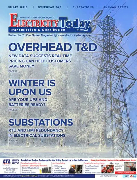
Data center PDU design covers floor- and rack-level power distribution units, branch circuit monitoring, A and B feed redundancy, phase balancing, and outlet selection- choices that determine how reliably power actually reaches the equipment plugged into it.
Everything upstream of the rack- switchgear, generators, UPS systems- exists to deliver clean, reliable power to one final piece of equipment: the power distribution unit that actually plugs into the server. A facility can get every upstream decision right and still deliver unreliable power at the rack if it treats PDU design as a commodity purchase rather than an engineering decision in its own right.
Data center PDU design sits at the point in the power chain where redundancy theory becomes the physical outlet a technician plugs a server into, and the gap between a well-designed PDU layout and a poorly designed one shows up there, in the last few feet of the distribution path.
How this choice fits into the broader redundancy model a facility has committed to is covered in Data Center Power Redundancy Design.
The first decision in data center PDU design is architectural. A floor PDU, typically a larger transformer-based unit serving multiple racks, centralizes monitoring and simplifies maintenance access, but a single unit failure affects several racks at once rather than one. Rack level PDUs distribute that risk across more, smaller units, at the cost of more individual devices to monitor, maintain, and eventually replace. Neither architecture is universally correct. Facilities running higher-density, higher-criticality workloads increasingly favor rack PDUs because the failure domain shrinks, even though the operational overhead of managing hundreds of individual units instead of a handful of floor units is real and has to be staffed for. Our companion course on Data Center Power Distribution Equipment - Construction and Operation covers both architectures in detail, including the busway and rack PDU construction standards each relies on.
Once the architectural choice is made, rack-level redundancy almost always follows an A and B feed design, where each server draws from two independent PDUs fed from separate upstream paths. This only delivers real protection if the two feeds actually trace back to independent sources all the way upstream, including separate Uninterruptible Power Supply units and, ideally, separate Automatic Transfer Switch paths. A facility that labels PDUs A and B but feeds both from the same upstream switchgear bus has created the appearance of redundancy without the substance, and that gap typically goes unnoticed until the shared upstream equipment fails and takes both paths down together.
Modern rack PDUs almost universally include branch circuit level monitoring, reporting current draw down to the individual outlet in many cases, and this capability has become less of a premium feature and more of a baseline expectation as facilities push rack density higher. The tradeoff is cost and complexity against visibility. A basic metered PDU reports aggregate load at the unit level, which is cheaper and simpler to deploy but leaves operators unable to identify which specific piece of equipment is driving an unexpected load increase. Branch circuit monitoring costs more per unit but turns a capacity-planning guess into an actual measurement, which matters far more once a facility is running close to its designed capacity than when it's well under it.
Tracing whether those two feeds actually reach independent sources upstream is easiest with the facility's own Data Center Electrical One-Line Diagrams in front of you.
Most PDUs distribute three phase power to single phase loads at the outlet level, and an unevenly loaded PDU, where one phase carries substantially more current than the other two, wastes available capacity and can trip a circuit breaker on the heavily loaded phase well before the PDU as a whole reaches its rated capacity. This is a genuinely common and avoidable design failure. Facilities that rack equipment without deliberately balancing load across phases as they go tend to discover the imbalance only when a breaker trips on one phase while the other two still have meaningful headroom remaining, a failure mode that a few minutes of deliberate outlet assignment planning would have prevented entirely.
Outlet type selection- C13 and C19 connectors for standard IT equipment, higher-amperage locking connectors like L6-30 for denser equipment- has real consequences for future flexibility. A PDU wired entirely for standard C13 outlets accommodates typical server equipment cleanly but may require costly reconfiguration if future equipment, particularly higher-density AI or HPC hardware, requires higher-amperage connections that were never planned for. Facilities anticipating density growth increasingly specify a mix of outlet types up front, accepting slightly higher initial cost in exchange for flexibility that avoids a disruptive mid-life PDU replacement.
Floor PDUs built around a K-rated input transformer are designed to tolerate the harmonic distortion switch-mode server power supplies generate, and specifying a standard transformer instead to save cost tends to age badly as IT load density increases. The same harmonic behavior addressed more broadly in Power Factor Correction Sizing and Harmonic Risk Control applies directly at the PDU transformer, since an undersized or non-K-rated unit running hot from harmonic current can fail well before its nameplate load rating would suggest it should.
The same harmonic behavior that stresses PDU input transformers runs through the entire distribution path, covered in Data Center Power Distribution and the Critical Power Chain.
PDU capacity planning ultimately traces back to decisions made far upstream, including the interconnection capacity available at the nearest electrical substation and the redundancy models covered in our course on Data Center Power Systems - Design and Reliability. A PDU sized generously for a Tier IV facility is wasted capacity in a Tier I deployment, and matching PDU redundancy and capacity to the facility's actual target reliability level, rather than defaulting to the most robust option available, is itself part of the design discipline.
Download our FREE Electrical Training Catalog and explore a full range of expert-led electrical training courses.

Data center PDU design is where every upstream engineering decision, redundancy model, harmonic tolerance, capacity planning, either gets honored or quietly undermined at the point where power finally reaches the equipment it was built to protect. A facility with excellent switchgear and a poorly specified PDU layout has not actually achieved the reliability its upstream design promised.
Advantages To Instructor-Led Training – Instructor-Led Course, Customized Training, Multiple Locations, Economical, CEU Credits, Course Discounts.
Request For QuotationWhether you would prefer Live Online or In-Person instruction, our electrical training courses can be tailored to meet your company's specific requirements and delivered to your employees in one location or at various locations.