Data Center Power Distribution and the Critical Power Chain
By R.W. Hurst, Senior Editor, The Electricity Forum
By R.W. Hurst, Senior Editor, The Electricity Forum

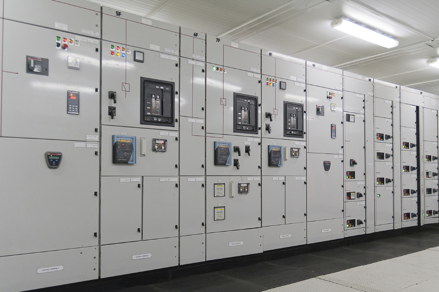
Data center power distribution routes electricity from the utility feed through switchgear, standby generators, uninterruptible power supply systems, and automatic transfer switches to rack level power distribution units, applying redundancy models that protect critical IT load.
Every facility that hosts servers, storage, and networking equipment depends on this same underlying path. Utility power enters at medium voltage, steps down through transformers, and passes through several stages of switching and conditioning before it reaches a single rack. The physical route is straightforward to describe. The engineering behind why each stage exists, and what happens when one link weakens, is where the discipline actually lives.
Facility managers, electrical contractors, and consulting engineers approach this topic from different angles. A contractor wants to know what equipment goes where. A facility manager wants to know what fails first under stress. A consulting engineer wants to know how redundancy choices affect cost and floor space. Data center power distribution has to answer all three without collapsing into a single narrow definition.
The path begins at the utility service entrance, where medium voltage switchgear receives incoming power and steps it down for facility use. From there, power typically splits across normal and standby paths, with standby generators positioned to carry the load if the utility feed fails. Data center power distribution is defined largely by how many parallel paths exist at each stage, since that number determines whether a single equipment failure interrupts service.
Where redundancy is decided stage by stage rather than facility-wide is covered in more depth in Data Center Power Redundancy Design.
Low- and medium-voltage switchgear forms the backbone of the distribution chain, housing circuit breakers that isolate faults before they cascade downstream. An Automatic Transfer Switch sits between the utility source and standby generation, sensing voltage and frequency abnormalities and shifting the load automatically when conditions warrant it. The choice between open-transition and closed-transition switching at this layer has real consequences for facilities that cannot tolerate even a brief interruption.
Between the transfer switch and the rack, an Uninterruptible Power Supply bridges the gap while a standby generator starts and synchronizes. This ride through window is not incidental. Engineers size it deliberately to match the generator start time, and undersizing it is one of the most common design errors in facilities retrofitted for higher-density loads. Battery chemistry, topology, and runtime targets all shift depending on how much risk the operator is willing to accept during that window.
Reading a facility one line diagram reveals how redundancy is actually implemented, not just claimed. An N configuration has no spare capacity. N plus 1 adds a single spare unit at a given stage. Two N duplicates the entire distribution path. Each model trades capital cost against tolerance for equipment failure or planned maintenance, and the correct choice depends on what the facility can afford to lose. Our course on Data Center Power Systems - Design and Reliability walks through how these models map onto real equipment configurations and which codes govern each stage.
Reactive load from motors, drives, and switching power supplies degrades power factor along the distribution path, and uncorrected power factor consumes transformer and cable capacity that would otherwise support additional load. Power Factor Correction Sizing and Harmonic Risk Control becomes relevant here, since undersized or poorly tuned correction equipment can introduce harmonic resonance rather than solve the original penalty problem. Protection coordination matters just as much. Every stage from the incoming breaker down to the rack level branch circuit depends on devices explained in What is a Circuit Breaker In Protection tripping in the correct sequence, so that a fault at one rack does not take down an entire distribution board.
Reading the full path this way is easier with an actual diagram in front of you, which Data Center Electrical One-Line Diagrams walks through in detail.
Large facilities often receive power from a dedicated or shared What Is An Electrical Substation? before it ever reaches the building switchgear, and utility side redundancy at that level shapes what is achievable downstream. For the physical equipment itself, switchgear construction, busway, and rack power distribution units, our companion course on Data Center Power Distribution Equipment - Construction and Operation covers construction, testing, and the standards each component is built to.
Data center power distribution is not a single piece of equipment or a single decision. It is a chain of interdependent stages, each governed by its own standards and capable of becoming the weak link if specified without regard to the stages around it.
At the far end of that chain, the equipment powering the rack itself is its own design problem, one covered separately in Data Center PDU Design: Rack Power and Metering.
Reliability in a data center is never the product of one component. Switchgear isolates faults, but it cannot compensate for an undersized UPS. A well-tuned automatic transfer switch means little if the generator behind it cannot start fast enough to cover the ride through window. That is why data center power distribution must be evaluated as one continuous chain rather than a shopping list of equipment. Facility teams that treat each stage in isolation often discover the gap only during an actual outage, when a redundancy assumption made years earlier no longer holds under current load. Reviewing the one line diagram periodically, not just at commissioning, is what keeps a facility's real redundancy aligned with what it was designed to deliver as loads, equipment, and density requirements change over the life of the building.
Stay informed with our FREE Power Systems For Data Centers Newsletter — get the latest news, breakthrough technologies, and expert insights, delivered straight to your inbox.
Explore 50+ live, expert-led electrical training courses –