Electrical Ground Clamp and Connection
By Frank Baker, Technical Editor
By Frank Baker, Technical Editor
Our customized live online or in‑person group training can be delivered to your staff at your location.

An electrical ground clamp is a small connection point that determines whether a grounding system remains electrically continuous under corrosion, vibration, and fault stress, or quietly degrades until a surge or fault event exposes the weakness.
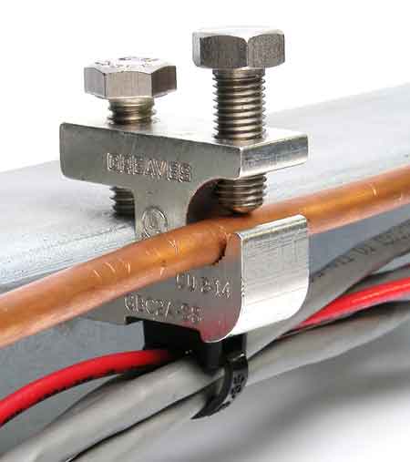
A ground clamp is not just a way to hold a conductor in place. It is the interface where copper meets metal, where pressure, surface condition, and material compatibility determine whether the intended return path remains predictable over years of service. That matters because grounding performance is not something you notice on a normal day. You notice it when something goes wrong, and the system has to behave exactly as designed.
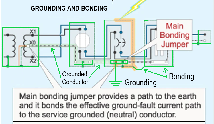
In simple terms, an electrical ground clamp bonds a grounding conductor to an electrode, enclosure, pipe, rebar, or structural steel so the system remains at a stable reference and abnormal energy has a designated path to ground. The clamp’s job is not theoretical. It must maintain a low-resistance, mechanically stable metal-to-metal connection through seasons, moisture, torque relaxation, and site abuse.
This is why clamp discussion belongs inside the broader logic of electrical grounding, because clamps are one of the points where a sound design can be undermined by a weak connection that slowly drifts out of spec.
Most clamp failures are not dramatic. They are slow. A fastener loosens slightly. Oxide forms at the contact surface. Dissimilar metals start a galvanic reaction. A clamp that tested fine at commissioning becomes a different component five years later.
The risk is not merely “poor grounding” in the abstract. The risk is a connection that adds resistance right where you least want it, at the junction that ties a conductor into bonded equipment. That is the moment where grounding and bonding stop being a textbook concept and become a practical reliability question about continuity, metal condition, and sustained contact pressure.
Stay informed with our FREE Power Quality Newsletter — get the latest news, breakthrough technologies, and expert insights, delivered straight to your inbox.
Catalogs list dozens of versions, but most electrical ground clamp choices fall into a few practical categories. The trick is to match the clamp to the metal geometry and the operating environment, not simply to the conductor size.
Ground rod clamps are designed to wrap around a cylindrical electrode and maintain consistent pressure. Good designs distribute force evenly and maintain stable contact even as the rod oxidizes or the clamp experiences seasonal movement at grade.
Pipe and rebar clamps are used when the bonded metal is irregular, coated, or not perfectly round. They need to bite clean metal without deforming it, and they need to tolerate real-world surfaces that are never as clean as a lab example.
Structural and beam clamps are common in industrial facilities where bonding to steel is required without drilling. These clamps can be excellent when properly matched, but they are unforgiving of paint, mill scale, or casual tightening. If the contact surface is not prepared, you can end up with a clamp that looks secure but is electrically unimpressive.
There are also specialty clamps for fences, panels, and grounding bus assemblies, and those devices often fail for the same reason: insufficient attention to contact quality and long-term stability.
A clamp’s material choice affects both conductivity and survival. Copper alloys and bronze are popular because they can hold torque, resist corrosion, and still conduct well. Pure copper can conduct beautifully, but can be soft, meaning it may relax under clamping pressure over time. Stainless steel hardware adds strength but can cause galvanic corrosion if paired poorly with copper components in a wet environment.
If your connection point is part of the grounding electrode conductor path, that metallurgy decision matters more than it first appears, because you are selecting the component that must stay electrically continuous for the life of the installation, not just pass an initial continuity check.
Two installations can use the same conductor gauge and require different clamps. Outdoor sites are subject to moisture, salt, soil chemistry, and freeze-thaw movement. Industrial interiors see vibration, chemical exposure, and frequent mechanical interference. A clamp that is perfectly fine in a dry electrical room may degrade quickly near process equipment, washdown zones, or coastal air.
When you evaluate a clamp, the useful questions are practical. What metal am I bonding to, and is it coated? Will this connection be disturbed by vibration or maintenance access? Will corrosion be a slow but constant force? Is the conductor likely to be re-terminated in the future, and will the clamp tolerate that without damage? Those are not “installation steps.” They are judgments that determine whether the clamp remains a real electrical connector or becomes a decorative one.
Under normal conditions, a ground clamp carries almost nothing. That is why weak connections can hide for years. During a fault, surge, or induced event, the clamp can briefly become a high-stress component. If the contact area is poor, resistance rises at the worst moment, heat builds, and arcing can occur at the interface.
This is directly tied to the way electrical ground faults behave, because fault performance depends on the integrity of the return path through bonded metal and conductors, and clamps are one of the places where that path can become unpredictable.
Think you know Power Quality? Take our quick, interactive quiz and test your knowledge in minutes.
Clamps become more consequential when the system has its own source, its own neutral treatment, or a complex bonding arrangement. Generator connections are a classic example, because the clamp is often part of a broader bonding and reference strategy that determines how abnormal current behaves. If you are working in that environment, it helps to understand the context around grounding a generator, because clamp choices are not isolated from the way the system establishes its reference and return behavior.
Similarly, installations that use controlled-fault-current methods will experience different stresses, inspection expectations, and performance assumptions than solidly grounded systems.
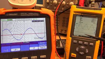
A common field surprise is finding a clamp that is physically present, apparently tight, yet electrically compromised. Rusted fasteners, oxidized contact surfaces, and loosened pressure points show up repeatedly in older installations. If a grounding test result is disappointing, connection points are often where the story begins.
This is why clamp evaluation belongs within the larger logic of a grounding system: the system only performs as well as its weakest link, and clamps are among the most common weak links when time and environment do their work.
Advantages To Instructor-Led Training – Instructor-Led Course, Customized Training, Multiple Locations, Economical, CEU Credits, Course Discounts.
Request For QuotationWhether you would prefer Live Online or In-Person instruction, our electrical training courses can be tailored to meet your company's specific requirements and delivered to your employees in one location or at various locations.