Electrical Ground Loop in Power Systems
By Frank Baker, Technical Editor
By Frank Baker, Technical Editor
Our customized live online or in‑person group training can be delivered to your staff at your location.
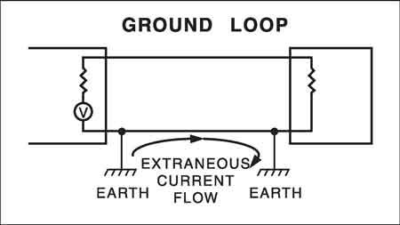
An electrical ground loop occurs when multiple grounding paths create unintended closed circuits, allowing circulating current, voltage differences, noise, and shock risk in building power systems, undermining grounding integrity and bonding function.
Grounding (sometimes referred to as "earthing") is intended to stabilize voltage, provide a reference to earth, and create a predictable fault-return path. When an earthing system unintentionally allows current to circulate through more than one conductive path, that stability begins to erode. This condition is known as an electrical ground loop, and while it is often discussed in abstract terms, it shows up in real buildings as unexplained voltage differences, circulating currents, and persistent power quality complaints.
A ground loop is not caused by a single conductor or device. It results from how earthing and bonding connections interact across an entire system. When two points that are assumed to be at the same electrical potential are connected by more than one conductive path, even small voltage differences can drive current through earthing conductors that were never intended to carry it.
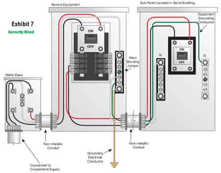
In practical installations, an electrical ground loop most often arises when grounding and bonding are extended without a clear system reference point. Service equipment, subpanels, separately derived systems, generators, and transformers all introduce opportunities for parallel earth paths if bonding is not carefully controlled. Metal raceways, structural steel, and auxiliary grounding connections can quietly become part of a loop when they bridge points that already share a grounding connection elsewhere.
Understanding how earthing is intended to function as a coordinated system rather than a collection of independent connections is central to avoiding these conditions, which is why many earthing issues trace back to misunderstandings that arise in discussions of understanding electrical grounding.

In practical installations, ground loops form when electrical devices are connected through multiple paths to ground that do not share the same ground potential, allowing unintended current to circulate between points at different voltage levels.
These circulating currents are often influenced by surrounding magnetic fields and become most noticeable when sensitive signal ground references are tied to power grounding conductors rather than controlled through a single point connection.
When grounding is spread across multiple paths rather than being intentionally referenced, small potential differences are amplified, creating noise, interference, or erratic behavior that cannot be resolved by component replacement alone.
The defining characteristic of an electrical ground loop is a circulating current driven by small voltage differences between grounding points. These differences may be caused by load imbalance, neutral current flow, fault conditions, or variations in impedance across earthing paths. Once current enters the grounding network, it can travel through equipment frames, bonding jumpers, or earth paths that were designed only for fault-clearing, not for continuous current.
This behavior becomes especially problematic when neutral and earthing relationships are misunderstood, since improper neutral bonding can encourage load current to migrate into earthing conductors, a distinction explored in electrical neutral vs ground.
While safety is always the primary concern, ground loops often manifest first as power quality issues. Sensitive equipment may experience noise, erratic operation, or unexplained interference that does not respond to conventional filtering or load-balancing efforts. Because earthing conductors are interconnected throughout a facility, these effects can appear far from the point where the loop actually exists.
A well-coordinated earthing and bonding strategy reduces these risks by ensuring that conductive paths behave predictably under both normal operation and abnormal conditions, reinforcing principles discussed in grounding and bonding.
Electrical codes do not prohibit multiple earthing connections. Instead, they establish conditions under which grounding conductors perform their intended role without becoming current-carrying pathways during normal operation. The challenge for system designers and electricians lies in applying those principles consistently as systems expand, equipment is added, or temporary connections become permanent.
Conductor sizing, bonding jumper placement, and earthing electrode connections all influence how current divides across available paths, which is why reference tools such as the NEC ground wire size chart indirectly control electrical ground loop behavior by limiting impedance disparities.
Ground loops are often intensified when earthing electrodes are added without regard for how they interact with existing connections. Multiple electrodes tied together through equipment bonding, building steel, or earth can introduce parallel paths with different resistances, creating conditions where circulating current becomes unavoidable under load or fault conditions.
Evaluating how each electrode is bonded to the system reference point clarifies the role of the grounding electrode conductor in maintaining a stable earthing network.
One of the most common mistakes in addressing electrical ground loops is focusing on individual components rather than the system as a whole. Removing a single connection may reduce symptoms temporarily while leaving the underlying loop intact. Effective resolution requires understanding how earthing paths interact across service equipment, distribution panels, and connected loads.
This broader view aligns with the way a complete grounding system is intended to function, as an integrated network rather than isolated conductors.
Think you know Power Quality? Take our quick, interactive quiz and test your knowledge in minutes.
Certain earthing approaches intentionally modify how fault current behaves, thereby altering how ground loops manifest. In systems that employ impedance between neutral and earth, circulating current behaves differently than in solidly grounded systems, making it important to understand how these designs influence unintended current paths, a concept related to high resistance grounding.
Electrical ground loops are not merely theoretical anomalies. They are indicators that an earthing system is behaving in ways its designers did not intend. For licensed electricians and system designers, recognizing a ground loop means thinking beyond individual conductors and viewing earthing as a coordinated architecture that governs safety, fault behavior, and power quality together.
When earthing is approached as a deliberate system rather than a collection of connections, the conditions that allow ground loops to form become easier to identify and far less likely to persist.
Explore 50+ live, expert-led electrical training courses –