Electrical Ground Symbol Explained
By Frank Baker, Technical Editor
By Frank Baker, Technical Editor
Our customized live online or in‑person group training can be delivered to your staff at your location.
Electrical ground symbol meanings include earth ground, chassis ground, and signal or common reference icons used in schematics and wiring diagrams. Understanding these symbols helps electricians read and interpret grounding in electrical systems with confidence.
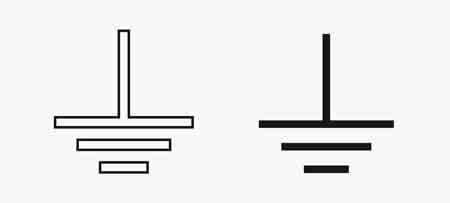
Electrical diagrams use specific symbols to convey how grounding is connected and referenced in a circuit. The simple icon that resembles three stacked horizontal lines narrowing downward usually denotes earth ground or protective reference in wiring. On many schematics, a triangle or a set of parallel lines indicates a grounding connection tied to the system's reference node, whereas a chassis connection bonds equipment frames for fault-current return. Professionals reading blueprints will recognize these symbols as shorthand for the various ways systems relate a circuit to zero potential and safety reference points rather than literal earth stakes. In residential and commercial power systems, proper interpretation of ground symbols ties back to the fundamentals of how and why we connect to earth and bonding infrastructure in installations.
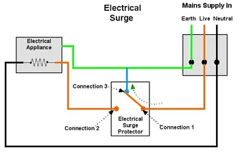
In industrial and panel wiring diagrams, the electrical ground symbol is drawn with a set of lines that decrease in length as they descend, indicating a connection to earth or protective ground. A chassis-ground symbol, often depicted as angled or diagonal lines intersecting a baseline, indicates that the chassis or enclosure serves as a return path or reference ground. Other symbols, such as a solid triangle, may serve as a reference ground in control circuits or signal diagrams. Because these symbols convey important relationships among conductors, grounding paths, and panels, electricians must be fluent in their meanings before interpreting or designing. This visual language of schematics supports safe installation practices and clear communication among designers and installers.
Stay informed with our FREE Power Quality Newsletter — get the latest news, breakthrough technologies, and expert insights, delivered straight to your inbox.
Understanding how a grounding electrode is illustrated in a plan helps you reconcile the drawing with actual field components. When tracing a ground conductor in a panel schedule, you will encounter the symbol that tells you this is not just any conductor but one intended to connect back to ground or protective earth. That ties directly to how we implement structured grounding and bonding in the systems covered today, much as in a comprehensive explanation of grounding and bonding fundamentals. A clear grasp of schematic symbols makes it easier to cross-reference equipment to the neutral vs ground conductor roles in service equipment.
The electrical ground symbol serves as shorthand for concepts that are defined and applied in real installations. For example, in the grounding electrode conductor context, you care about how a symbol relates back to the actual conductor that runs to a driven rod or plate, something discussed in depth in grounding electrode conductor explanations. Similarly, a symbol on a panel drawing pointing back to the grounding bar has implications for the entire grounding system, tying into broader discussions of electrical grounding. When reviewing drawings on site, it is not unusual to reconcile a schematic with the physical grounding electrical panel layout and verify connections match what the ground symbols depict.
Beyond safety, correctly interpreting the electrical ground symbol can influence how you troubleshoot power quality issues in a distribution system. A misinterpreted symbol could lead you away from recognizing a ground loop condition or a potential difference between reference points, aspects that seasoned electricians will consider when evaluating a circuit. For a practical foundation on how grounding affects current flow and safety, the discussion on what electrical grounding is gives context that complements schematic literacy.
From my experience reviewing panel wiring diagrams and control schematics over the years in commercial service environments, the subtle differences between earth, chassis, and common ground symbols become apparent early in schematic study but only intuitive after repeated real-world application. Many electricians initially learn about the electrical ground symbol in boardrooms or classrooms, but it is only when they stand at a service disconnect or trace a conduit full of green/bare conductors that the relevance clicks. Professional judgment in interpreting symbols matters because a missed nuance can lead to reading a grounding connection as a functional return instead of a protective earth, with implications for fault-current paths and equipment bonding.
Related Articles
• Understanding electrical grounding
• Electrical neutral vs ground
• Grounding electrode conductor
• What is electrical grounding
Download our FREE Electrical Training Catalog and explore a full range of expert-led electrical training courses.

Advantages To Instructor-Led Training – Instructor-Led Course, Customized Training, Multiple Locations, Economical, CEU Credits, Course Discounts.
Request For QuotationWhether you would prefer Live Online or In-Person instruction, our electrical training courses can be tailored to meet your company's specific requirements and delivered to your employees in one location or at various locations.