Electrical Ground Rod Installation Guide
By Frank Baker, Technical Editor
By Frank Baker, Technical Editor
Our customized live online or in‑person group training can be delivered to your staff at your location.

Electrical ground rod installation determines how effectively fault current, lightning energy, and surges dissipate into soil. Proper depth, spacing, bonding, soil conditions, and code-aligned placement decide whether a grounding system protects assets.
That reality is why ground rod installation is not a trivial task or a generic “how-to.” It sits at the intersection of soil behavior, conductor physics, and code intent, and its success depends as much on judgment as it does on technique.
Installing a ground rod is often treated as a procedural obligation rather than a system decision. In practice, the rod becomes the interface between an electrical system and the earth itself, and that interface behaves very differently depending on soil composition, moisture, and surrounding electrical conditions. A single rod driven eight feet into dry, rocky soil will not behave the same way as the identical rod installed in loam or clay, even though both may appear compliant.
This is why experienced electricians think about grounding as a system rather than an accessory. The rod must be placed where it can dissipate energy, remain mechanically stable over time, and stay electrically unified with the rest of the grounding network. When those conditions are ignored, the rod may exist physically while contributing very little electrically, an outcome that becomes clearer when grounding is examined as part of a complete grounding system rather than as a single component.
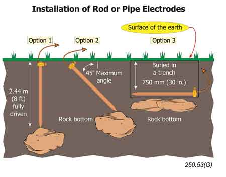
Most installations begin with the familiar requirement to drive a rod vertically into undisturbed soil to sufficient depth. That depth reflects the need to reach soil layers with consistent moisture and lower resistivity, which directly affects how fault and surge currents spread into the earth. Shallow installations tend to concentrate energy near the surface, increasing step potential and reducing dissipation effectiveness.
Download our FREE Electrical Training Catalog and explore a full range of expert-led electrical training courses.

Spacing becomes relevant as soon as more than one rod is used. Placing rods too close together causes their electrical influence zones to overlap, offering little improvement over a single rod. Proper spacing allows each rod to interact with a fresh volume of soil, increasing overall performance rather than simply adding metal. These placement decisions align with the intent of the modern electrical grounding code, which emphasizes performance rather than physical dimensions.
Installation locations should also be chosen with long-term stability in mind. Areas subject to erosion, frost movement, or repeated excavation introduce a mechanical risk that quietly undermines grounding effectiveness over time.
Driving a rod seems straightforward until soil conditions complicate the process. Rocky ground, compacted fill, or shallow bedrock often forces installers to adapt. In those cases, judgment matters more than brute force. Angled installations or horizontal methods can be acceptable when vertical driving is impractical, but only when executed with an understanding of how soil contact affects dissipation.
Tools matter here. Mechanical drivers reduce deformation and protect the conductive cladding, which is critical for corrosion resistance. A rod that is damaged during installation may perform adequately at first but degrade faster than expected, particularly in aggressive soils.
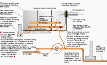
The connection between the rod and the grounding conductor is where many otherwise sound installations fail. A loose clamp, improper connector type, or corrosion-prone joint introduces resistance at the exact point where continuity matters most. That resistance often remains invisible until a fault or surge event reveals it.
Connections must be mechanically secure, electrically continuous, and rated for direct burial. Exothermic welding offers permanence, while listed clamps can perform well when installed correctly and protected. Regardless of the method, the rod must be electrically connected to the grounding electrode conductor, as explained in detail in the guide to grounding electrode conductors.
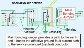
This is also where grounding transitions into bonding. The rod does not operate in isolation; it must be coordinated with equipment enclosures and conductive paths throughout the installation, a relationship explored more fully in grounding and bonding practice at grounding and bonding.
Soil resistivity is the silent variable in every ground rod installation. Two installations that look identical on the surface can perform very differently depending on moisture content, mineral composition, and seasonal variation. Dry sand and rocky soil offer high resistance, while clay and loam typically provide better conductivity.
In challenging soils, adding rods or increasing depth may be necessary to achieve acceptable performance. Ground enhancement materials are sometimes used, but they are design tools, not universal solutions. Their effectiveness depends on placement, moisture retention, and long-term stability—factors that reinforce why grounding must be evaluated as a system rather than as an isolated task.
Understanding this broader context is central to understanding electrical grounding, where performance is measured by behavior under stress, not by appearance at inspection.
Ground rod installation does not end when the rod disappears below grade. Verification confirms whether the installation performs as intended. In some environments, resistance testing provides insight into effectiveness, especially where soil conditions are unpredictable. Even when testing is not mandated, inspection of connections and conductor routing remains essential.
Over time, environmental exposure and site changes can degrade performance. Grounding systems benefit from periodic review, particularly after electrical modifications or landscaping changes. Techniques for confirming continuity and effectiveness are outlined in how to check if an area is grounded, which connects installation decisions to measurable outcomes.
Stay informed with our FREE Power Quality Newsletter — get the latest news, breakthrough technologies, and expert insights, delivered straight to your inbox.
A ground rod is only one element in a broader electrical safety framework. It works alongside bonding practices, conductor sizing, and system design choices that determine how fault energy flows and how voltages stabilize. In specialized applications, such as agricultural enclosures or perimeter systems, those same principles apply, as seen in electric fence ground rod installations, where soil contact and spacing directly affect system reliability.
When electrical ground rod installation is approached as a system decision rather than a procedural step, the result is a grounding connection that performs when it matters. That distinction separates installations that merely pass inspection from those that protect people, equipment, and operations under real-world conditions.
Advantages To Instructor-Led Training – Instructor-Led Course, Customized Training, Multiple Locations, Economical, CEU Credits, Course Discounts.
Request For QuotationWhether you would prefer Live Online or In-Person instruction, our electrical training courses can be tailored to meet your company's specific requirements and delivered to your employees in one location or at various locations.