Latest HV Testing & Maintenance Articles
Insulation Resistance Explained
Insulation resistance indicates how effectively insulation prevents current leakage, thereby supporting electrical safety and reliability. Testing measures dielectric strength, detects moisture and aging, and guides maintenance to avoid faults while extending equipment life.
Quick Reference: Insulation Resistance Explained
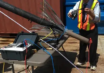
The Insulation Resistance (IR) test, often referred to as the Megger test, is over 100 years old and is considered a straightforward test. During my 15 years of inspection and testing work in Canada, the US, and internationally, I have observed various practices for performing and interpreting IR tests. Understanding dielectric voltage testing is essential when evaluating insulation resistance because it…
View more
Sign Up for Electricity Forum’s HV Testing & Maintenance Newsletter
Stay informed with our FREE HV Testing & Maintenance Newsletter — get the latest news, breakthrough technologies, and expert insights, delivered straight to your inbox.
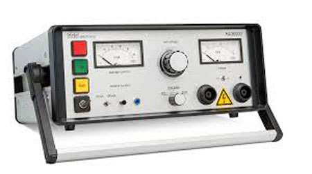
Hipot Testing Explained
Hipot testing checks electrical insulation strength by applying high voltage to confirm there are no current leaks. It is essential for ensuring safety, detecting faults, and preventing electrical failures in power equipment, cables, transformers, and other high-voltage systems.
Basics of Hipot in Electrical Engineering
Also known as dielectric withstand, hipot testing applies high voltage to confirm that insulation can endure operating and surge conditions without breaking down. This test is crucial across various industries, including medical devices, automotive electronics, and aerospace systems, where insulation failure can pose life-threatening hazards. Companies that fail to conduct a proper dielectric strength test…
View more
Dielectric Voltage Withstand Test Explained
The Dielectric Voltage Withstand Test applies high voltage to verify insulation strength. It ensures transformers, wiring, and switchgear resist breakdown, helping prevent electrical hazards and confirming compliance with essential safety standards.
How the Dielectric Voltage Withstand Test Improves Electrical Safety
The Dielectric Voltage Withstand Test is a critical safety procedure that every industrial electrician should be familiar with. This procedure, also known as a hipot test or high potential test, evaluates the effectiveness of electrical insulation in preventing potentially dangerous voltage breakdowns. By understanding the principles and applications of this procedure, industrial electricians can ensure the safety of electrical…
View more
Line Leakage Testing: Is It Right For Your Application
Line leakage testing evaluates unintended current paths under normal and single-fault conditions, ensuring electrical safety, touch current compliance, insulation integrity, and adherence to IEC 60990, IEC 60601, UL standards for equipment and medical devices.
The Importance of Line Leakage Testing in Electrical Safety
The Line Leakage test (LLT for short) is most often specified to be performed as a type test in a design or engineering laboratory or as a routine production line test on medical devices right before they ship. Not as commonly performed as a Dielectric Withstand or Ground Bond test in a production environment, LLT can…
View more
Ground Tester Section Criteria
Ground tester ensures accurate earth resistance, grounding integrity, and soil resistivity measurements using clamp-on, 3-point/4-point methods, plus loop impedance testing, boosting IEC/NEC safety compliance for electrical installations, bonding continuity, and earthing fault protection.
Understanding How a Ground Tester Works
Ground Tester Section Criteria is important to decide. The electrical grounding component of an electrical facility can be easily overlooked. It doesn’t appear to have an active role. It isn’t moving, doesn’t emit light or sound, or provide data. It’s largely out of sight. But the electrical ground is in fact dynamic. It gets challenged and stressed like any other…
View more
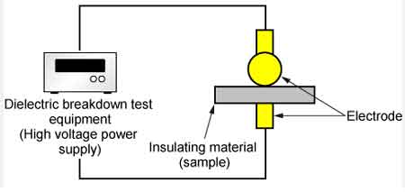
Dielectric Voltage Testing - Standard Methods
Dielectric voltage testing verifies insulation strength via hipot, withstand voltage, and leakage current limits, ensuring electrical safety, IEC/IEEE compliance, and quality assurance across power systems, switchgear, transformers, cables, and consumer electronics.
How Dielectric Voltage Testing Works
There are two standard methods from ASTM International: D877, Standard Test Method for Dielectric Breakdown Voltage of Insulating Liquids Using Disk Electrodes, and D1816, Standard Test Method for Dielectric Breakdown Voltage of Insulating Oils of Petroleum Origin Using VDE Electrodes.VDE stands for Verband Deutscher Electrotechniker—the Association for Electrical, Electronic, and Information Technologies— a German standards organization similar in function to the Institute of…
View more
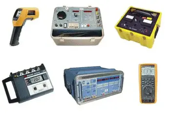
Why Calibrate Test Equipment
Calibrate test equipment to ensure accuracy, traceability, and compliance in electrical labs using ISO 17025 procedures, NIST standards, and metrology best practices for multimeters, oscilloscopes, power analyzers, and signal generators.
Principles of Calibrating Test Equipment
You’re serious about your electrical test instruments. You buy top brands, and you expect them to be accurate. You know some people send their digital instruments to a metrology lab for calibration, and you wonder why. After all, these are all electronic — there’s no meter movement to go out of balance. What do those calibration folks do, anyhow — just change the battery?…
View more