Latest Electrical Substations Articles
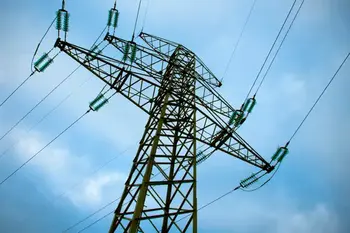
Vibration and Noise Control in T&D
Vibration and Noise Control in TD integrates acoustics, damping, isolation, and vibration analysis to mitigate resonance, reduce sound pressure, enhance structural dynamics, and ensure compliance with ISO standards across turbomachinery and thermal design.
Vibration and Noise Control in TD Explained for Electrical Professionals
T&D industry trends and requirements have put great demand for low noise equipment with good long term performance. Amorim Cork Composites as a worldwide supplier to the T&D Industry has invested in R&D, establishing its VC (Vibration Control) product range and successfully implementing noise reduction solutions through vibration control.In parallel, best practices in electrical substation design…
View more
Sign Up for Electricity Forum’s Electrical Substations Newsletter
Stay informed with our FREE Electrical Substations Newsletter — get the latest news, breakthrough technologies, and expert insights, delivered straight to your inbox.
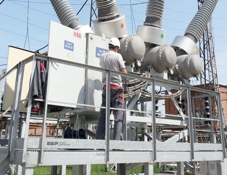
Electrical Substation Maintenance: Protecting Assets
Electrical substation maintenance keeps transformers, breakers, and protection systems reliable through inspection and testing. It reduces outages, improves safety compliance, extends equipment life, and supports grid operations.
Electrical Substation Maintenance Overview
Electrical substation maintenance is not simply a routine task performed at fixed intervals. It is an ongoing process that supports the stability of transmission and distribution networks by ensuring that high-voltage equipment operates as intended under normal and abnormal conditions. Substations concentrate critical assets in one location, which means small defects can escalate quickly if they go unnoticed. Effective maintenance reduces uncertainty by keeping equipment condition visible and…
View more
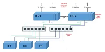
RTU and HMI Redundancy in Electrical Substations
RTU and HMI redundancy enhances SCADA reliability with failover, hot standby controllers, mirrored databases, dual networks, and fault tolerance, delivering high availability, minimized downtime, and resilient industrial automation for critical process control.
RTU and HMI Redundancy Explained
As the substation RTU takes on more applications, such as Human-Machine-Interface (HMI), alarm annunciation, math & logic and “relay communication processing”, its need for high availability increases. Anything that takes the RTU out of service – configuration change, firmware update, or component failure – means not only loss of SCADA but also loss of local visibility, loss of non-operational data and, in…
View more
Vacuum Circuit Breaker Protection
A vacuum circuit breaker is chosen not because it interrupts current, but because it determines how reliably a medium-voltage system survives faults, switching cycles, and long-term maintenance exposure. The decision to specify a VCB controls arc behavior, service intervals, environmental risk, and fault-clearing confidence in substations and industrial power systems where failure carries operational and safety consequences.
When a Vacuum Circuit Breaker Is the Right Decision
Vacuum circuit breakers are most effective when system reliability must be preserved without introducing maintenance burden or environmental liability. In medium-voltage applications, the choice is rarely about whether a breaker can interrupt current,…
View more
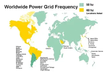
Why Electrical Frequency Supply is 50 Hz or 60 Hz?
Electrical frequency supply ensures 50/60 Hz AC power, grid stability, frequency regulation, power quality, and synchronized operation across generation, transmission, and distribution networks, supporting loads, inverters, and synchronous machines reliably.
Why Electrical Frequency Supply Matters in Power Distribution
Many many years ago we did not have integrated power system as we have now. There were multiple standards and load items which weresuitable for their power system. Operating electrical frequency ranges were between 16.75 Hz to 133.33 Hz.When people think about large power generation system, they puzzled with the standard that to be adopted by them. Finally it reveals about…
View more
How to Become a Substation Technician
How to become a substation technician requires technical training, knowledge of electrical safety, and field experience. This career supports power systems, substation maintenance, and grid reliability, while offering opportunities for advancement in the utility industry.
How to Become a Substation Technician?
An apprentice substation technician learns how to work safely with both AC and DC electrical systems, gaining hands-on experience under the supervision of experienced professionals. Training emphasizes the proper use of personal protective equipment PPE to reduce hazards, while developing the skills to troubleshoot and repair critical substation equipment. To better understand the fundamentals of substations, see our…
View more
Substation Breaker - T&D Protection
A substation breaker is a critical device in electrical substations, designed to interrupt fault currents, protect transformers, and safeguard distribution systems. It ensures reliability, safety, and efficient power flow across industrial, utility, and commercial networks.
Substation Breaker Explained: What You Need to Know
A substation breaker is a critical device within electrical substations, playing a fundamental role in the transmission and distribution (T&D) of electrical power. It is designed to interrupt the flow of electrical current in the event of a fault, such as a short circuit or overload, thereby protecting vital equipment and ensuring system stability. By isolating…
View more


