Latest Wiring Devices Articles
How to Bend Conduit
Use a hand bender to mark, align, and bend EMT conduit precisely. Apply steady pressure for clean 90°, offset, or saddle bends. This ensures proper routing and code compliance in electrical installations.
How to bend conduit
Bending electrical conduit is a vital skill for electricians and DIY enthusiasts working on electrical installations. Proper bends ensure that wiring is protected, neatly routed, and compliant with electrical code requirements. Here’s what you need to know:
✅ Accurate bends use hand benders with alignment marks
✅ Includes 90°, offset, and saddle bends
✅ Essential for clean, code-compliant conduit runs
Use a hand bender to mark, align, and bend EMT conduit precisely. Apply steady pressure for clean 90°, offset, or saddle bends. This ensures proper routing and code compliance in electrical installations.
Using the right tools and techniques, you can achieve precise bends—including 90-degree angles, offsets, and saddles—to navigate obstacles and fit conduit into tight spaces. This guide walks you through the process and key considerations to help you master the art of bending conduit effectively.
When learning how to bend conduit, understanding the techniques for making precise bends is essential. A 90-degree bend is one of the most common and useful for routing EMT conduit around corners or obstacles, requiring careful measurement and execution. Electricians must determine the stub height, the distance from the end of the conduit to the beginning of the bend, before aligning the bender. A 45-degree bend, by contrast, is useful for smoother transitions and changes in direction, especially when the conduit must rise or fall through narrow spaces. Measuring and marking carefully before you bend ensures accuracy, reduces waste, and improves installation efficiency.
Equipping Yourself: The Electrician's Toolkit
Every craftsman knows that the right tools are essential. Your toolkit is an extension of your skill, allowing you to shape metal with precision and artistry. At its core lies the conduit bender, a tool as versatile as the electrician who wields it. For tackling rigid types like IMC, the hickey bender provides the leverage needed to conquer stubborn curves. Hand benders, with their compact design, are ideal for EMT and smaller sizes, allowing for quick and accurate bends in tight spaces. And when the job demands taming large-diameter pipes, the hydraulic tool steps in with its raw power.
Beyond the bender, precision is paramount. A sharp conduit cutter ensures clean cuts, the foundation of accurate work. Your tape measure meticulously marks bend points and calculates angles. A level ensures your runs are plumb and true, especially for vertical sections and offsets. A permanent marker clearly indicates points, while an angle finder verifies those critical angles. And finally, your fish tape or pull wire stands ready to thread conductors through your flawlessly shaped conduit.
Every tradesperson knows that the right tools make the job easier—and more professional. When it comes to bending conduit, your essential toolkit includes:
-
Hand bender: Best for EMT (½", ¾", 1") and marked for precision
-
Hickey bender: Useful for rigid conduit like IMC
-
Hydraulic bender: Used for large-diameter conduit and tight-radius work
-
Conduit cutter: Produces clean, square cuts to ensure bend accuracy
-
Measuring tape: For locating bend points and calculating spacing
-
Permanent marker: To clearly mark bend locations
-
Level and angle finder: Verifies vertical and horizontal alignment
-
Fish tape or pull wire: Helps guide conductors through finished conduit runs
Take-Up Table: EMT Conduit
Understanding take-up is critical. This is the length of conduit “used up” by a 90° bend and must be subtracted from your total length when marking the bend point.
| EMT Size | Take-Up Length |
|---|---|
| ½-inch | 5 inches |
| ¾-inch | 6 inches |
| 1-inch | 8 inches |
For example, if you want an 18-inch stub using ½-inch EMT, mark the conduit at 13 inches (18 - 5 = 13) before bending.
Offset Multipliers
When creating offset bends to go around obstacles, you use a pair of equal bends—commonly at 10°, 22.5°, 30°, or 45°. Spacing is calculated using the offset height and a multiplier:
| Bend Angle | Multiplier |
|---|---|
| 10° | 6.0 |
| 22.5° | 2.6 |
| 30° | 2.0 |
| 45° | 1.4 |
So, if you need to clear a 4-inch obstruction with a 30° bend: 4 × 2 = 8 inches between bends.
The Art of the Bend: A Step-by-Step Guide
Bending conduit is a blend of muscle memory and precision. Begin by marking your conduit based on the type of bend you need. Position it in the bender so the mark aligns with the arrow or star on the shoe (depending on the bend). Place your foot on the pedal, apply steady pressure, and bend until the desired angle is reached—checking with an angle finder or level as needed. If the bend falls short or goes too far, make small corrections by reversing or over-bending slightly.
Bend Types to Master
Different bend types serve different practical needs on the job:
-
90° Bend (Stub-Up): The standard vertical bend used to route conduit up from a box or floor
-
Offset Bend: Two equal bends to navigate an obstacle or change elevation
-
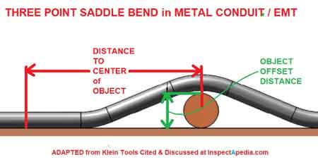
Saddle Bend: A three-point bend that goes up and over pipes or beams
-
Back-to-Back Bend: Two 90° bends in opposite directions to form a U- or Z-shape
-
Kick Bend: A single angled bend to slightly lift or lower the conduit at one end
Mastering these shapes expands your flexibility on the job site and ensures clean, functional installations.
Bend Radius: The Geometry of Conduit Shaping
This is the distance from the center of the curve to the inner edge of the pipe, is crucial for preventing kinks and maintaining structural integrity. This value is carefully calculated based on the pipe's size and type. Refer to the manufacturer's instructions or a bending chart for specific guidelines. For instance, a common radius for 1-inch EMT is 4 inches. By adhering to these guidelines, you ensure smooth, flowing curves that preserve the pipe's strength.
Preventing Kinks and Flattening
Even with the right tools and calculations, the pipe can be unforgiving. Kinks and flattening can weaken it, compromising the electrical system. Avoid these pitfalls by applying steady pressure throughout the process. Use the correct bender, and exercise restraint, remembering that overdoing can weaken the pipe. For longer bends, support the pipe to prevent sagging. With practice, you'll develop a feel for its limits.
Conduit Bend Types: Navigating the Electrical Landscape
To navigate obstacles and create functional wiring systems, electricians employ a variety of types. Offset bends shift the run horizontally or vertically. Saddle bends clear obstacles, maintaining proper spacing. Kick bends change the direction of the run at an angle. Back-to-back bends create Z-shaped offsets. Mastering these types empowers you to tackle complex installations with confidence.
Safety First: Protecting Yourself and Your Craft
In electrical work, safety is paramount. Working with conduit involves inherent risks that demand respect. Always wear safety glasses and gloves. De-energize circuits before working on any pipes. Be mindful of your surroundings. By adhering to safety protocols, you not only protect yourself but also demonstrate professionalism.
Shaping conduit is more than a mechanical process; it's a testament to the electrician's skill. By understanding the principles, mastering the techniques, and utilizing the right tools, you can elevate your expertise. Consult the manufacturer's instructions and adhere to all relevant electrical codes. With dedication and practice, you can transform ordinary pipes into functional works of art.
Related Articles
Sign Up for Electricity Forum’s Wiring Devices Newsletter
Stay informed with our FREE Wiring Devices Newsletter — get the latest news, breakthrough technologies, and expert insights, delivered straight to your inbox.
General Condition Assessment of XLPE and PILC Cables
Assessment of XLPE and PILC Cables covers diagnostics, condition monitoring, insulation testing, partial discharge analysis, tan delta, VLF, sheath integrity checks, and lifecycle asset management to enhance reliability, safety, and fault prevention.
What Is the Assessment of XLPE and PILC Cables?
A systematic evaluation using diagnostics to determine cable condition, risks, and maintenance needs.
✅ Conduct PD, VLF, and tan delta tests to gauge insulation health.
✅ Analyze sheath integrity, TDR traces, and thermography for defects.
✅ Score asset condition to plan maintenance, refurbishment, or replacement.
GE Energy uses non-destructive diagnostic technology to measure the overall health of a power cable, to reveal existing cable defects through partial discharge testing, and to predict the future life expectancy of the cable. Cable testing helps our customers to be proactive in preventing costly forced service outages while optimizing their capital budgeting for replacement programs. This offering applies to medium- and high-voltage shielded power cable (5-25 kV XLPE cables and 5-500 kV PILC cables) with a maximum length of 1.5 to two miles. The cables to be tested can be overhead, in cable trays, in duct bank, or buried. The GE Energy solution includes both general condition assessment and partial-discharge technologies. This paper will address only the general condition assessment technology. For a broader overview of techniques for asset condition assessment, see the Electricity Forum's power cable diagnostics guide for context on PD detection and lifecycle modeling.
DIAGNOSTICS OF XLPE (CROSS-LINKED POLYETHYLENE) CABLES
One of the major causes of failures in XLPE insulated cables is water-treeing. Water-tree deterioration process is very slow (5-50 years) and can vary from cable to cable, among different designs, and also among individual cables of same design. Earlier studies have shown that the dielectric response, obtained by dielectric spectroscopy measurements performed at high voltage levels, is correlated to water-tree content and breakdown voltage. Higher losses and increasing non-linearity of frequency response are associated with lower breakdown voltage. Understanding the relationship between dielectric losses and the principles in insulation resistance explained can help interpret slope changes and voltage dependence more confidently.
Water-tree measurement on XLPE cable requires an IDA 200* insulation diagnostics unit with the IDA HVU (High Voltage Unit) option. The diagnostic approach is based on extent of non-linearity of XLPE cable insulation. In performing a general condition assessment on XLPE cable, the dielectric spectroscopy technology shows the severity of water-trees in the insulation. The water-tree aging process is very slow, but it is important to understanding the degree of damage to the insulation. A heavily aged cable can fail catastrophically if the insulation stress is increased quickly (i.e. lightning impulses or faults). The HVU is used with the IDA 200 system to increase the output voltage up to 30 kV (21 kVrms). The main application for this combination is for diagnosis of water-tree deteriorated extruded power cables. The system works equally well when other types of non-linear materials are to be characterized. Field crews should follow established cable handling and testing procedures to ensure safe setup of the IDA 200 and HVU in energized environments.
DIAGNOSTICS OF PAPER INSULATED (PILC) CABLES
The three most commonly seen problems in PILC cables are partial discharge (cable itself and joints), moisture ingress, and thermal aging and resulting increase of moisture content (not dangerous by itself). In performing a general condition assessment on paper-insulated cable, the dielectric spectroscopy technology allows for estimation of average moistening of the insulation. Moreover, the presence of other defects, such as developing short-circuit due to carbonizing of paper, may be identified. Measurements on PILC cables are normally performed with the IDA 200 system only. Test voltage is by default 140 Vrms and frequency range 0.01-1000 Hz. Frequency response of a paper insulated cable can reveal worsening of insulation condition which is caused, for example, by an increase of moisture content. For locating and characterizing PD sources in substations and vaults, modern FLIR PD acoustic imaging can provide rapid screening before detailed dielectric assessment.
TECHNICAL DESCRIPTION OF IDA 200
The system (IDA 200) measures the impedance of a specimen at a variable voltage and frequency. A Digital Signal Processing (DSP) unit generates a test signal with the desired frequency. This signal is amplified with an internal amplifier and then applied to the specimen. The voltage over and the current through the specimen are measured with high accuracy using a voltage divider and an electrometer (ampere meter). The diagnostic measurement is performed by applying a relatively low voltage (up to 140 Vrms). The IDA 200 system measures the capacitance and dielectric losses at discrete frequencies both above and below the main frequency (output signals with frequencies from 0.1 mHz to 1 kHz are available). By avoiding the main frequency and its harmonics, an efficient filtering of their corruptive effects is enabled. These measurement strategies align with best-practice power cable test methods used across utilities for benchmarking insulation performance.
The diagnostic measurement is performed by applying a relatively low voltage (up to 140 Vrms). The IDA 200 system measures the capacitance and dielectric losses at discrete frequencies both above and below the main frequency (output signals with frequencies from 0.1 mHz to 1 kHz are available). By avoiding the main frequency and its harmonics, an efficient filtering of their corruptive effects is enabled.
DATA INTERPRETATION XLPE CABLES
The IDA 200 system helps to identify water-treeing in an extruded power cable. There are four different responses that will help to determine the health of the cable: low losses and no voltage dependence, VDP response, TLC response and LC response. LOW LOSSES AND NO VOLTAGE DEPENDENCE Graph 1 is an example showing capacitance changes in a cable having good overall health (dry cable). The cable was frequency swept from 0.1 Hz to 1 Hz at 3kV and 6kV. When the voltage is varied from 3kV to 6kV, the capacitance remains relatively the same, thus indicating a good condition of the cable. Moreover, when the 3kV and 6kV tests were performed, the frequency response was repeatable showing that the cable behaves consistently when voltage is varied. Similar condition-monitoring principles are applied in transformer oil testing to trend dielectric strength and contaminants across a fleet.
VDP RESPONSE
A voltage dependent increase of capacitance and loss. Graph 2 displays the capacitance changes that show a dry cable vs. a moist cable. Both cables were frequency swept from 0.1 Hz to 1 Hz at 3kV and 6kV. When looking at the dry cable, the voltage is varied from 3kV to 6kV and the capacitance stays relatively the same, thus indicating a good condition of the cable. If we look at the moist cable, when the voltage is varied from 3kV to 6kV, the capacitance increases with voltage. Looking at the moist cable, when the 3kV, 4.5kV and 6kV tests were performed, the frequency response is also not repeatable indicating water-treeing is present in this cable.
CONCLUSION
The IDA 200 test set can be used to help identify watertreeing in XLPE as well as moistening of the PILC cables. By identifying water-treeing in XLPE cables, increased moisture content in PILC cables and other defects in both types of cables, customers will have the ability to create a cost effective maintenance program for their cables and thus increase the reliability of their network. Informed by these diagnostics, utilities can integrate power transformer health checks into broader maintenance strategies for substations and feeders.
From: Wire and Cable and Wiring Methods Handbook, Vol 3, The Electricity Forum
Related Articles
EMT Electrical Conduit
EMT electrical conduit, also called thin-wall conduit, is a lightweight metal tubing used to protect and route electrical wiring. Made from galvanized steel or aluminum, EMT conduit offers durability, easy bending, and cost-effective installation for residential, commercial, and industrial applications.
What is EMT Electrical Conduit?
EMT electrical conduit, also known as electrical metallic tubing, is a popular choice for protecting and routing wiring in residential, commercial, and industrial wiring projects. It is:
✅ Lightweight, thin-wall metal tubing made from steel or aluminum
✅ Protects and routes electrical wiring in buildings
✅ Easy to bend, cut, and install for versatile applications
Known for its lightweight, cost-effective design, EMT is often referred to as thin-wall tubing due to its slimmer structure compared to rigid alternatives. Its galvanized steel construction provides corrosion-resistant properties, making it suitable for a variety of environments, including both indoor and outdoor wiring installations. The lightweight design makes it easier to handle during installation, while the galvanized steel helps protect the wiring inside. While commonly used in dry locations, it can also be applied in wet locations with the appropriate fittings, such as compression couplings, to ensure a watertight seal. EMT’s ability to be installed in both exposed and concealed locations adds to its versatility. This article will explore its advantages, compare it to other tubing options, and discuss when it’s best to use.
Frequently Asked Questions
What are the advantages and disadvantages of using EMT electrical conduit?
One of the major advantages of EMT is its easy installation and versatility. Being lightweight, it’s easier to handle and can be bent with standard tools, making it suitable for a range of applications, from residential to industrial wiring. Additionally, EMT is cost-effective, fire-resistant, and non-magnetic, making it a safe and durable choice for many environments. However, it is not as strong as rigid alternatives, which makes it more prone to damage in environments where physical impact is likely. Therefore, it’s not recommended for hazardous locations or areas where heavy wear and tear are expected.
How does EMT compare to other types of EMT conduit?
Compared to rigid metal options, EMT is much more flexible and easier to install. While rigid types offer more durability, they require specialized tools and techniques, making installation more labour-intensive. EMT, on the other hand, is more cost-effective, as it requires fewer specialized tools, which helps reduce overall project costs. While rigid tubing might be preferred for heavy-duty applications, EMT works well for general-purpose commercial and residential wiring. In wet locations, PVC conduits are often preferred, but EMT can be used with the proper watertight fittings.
Is EMT electrical conduit suitable for outdoor use?
Yes, EMT can be used for outdoor wiring if installed with appropriate weatherproof fittings that ensure a watertight seal. While primarily used for indoor wiring, its corrosion-resistant properties allow it to be safely used outdoors in exposed locations. To ensure long-term performance in wet locations, it’s important to install EMT with weatherproof connectors, clamps, and straps. Always follow NEC guidelines for compliant installation.
How do I bend EMT conduit, and what tools are needed?
Bending EMT is relatively simple due to its flexibility. A standard bender can be used to create precise angles, allowing the tubing to navigate around obstacles or fit into tight spaces. When bending EMT, it’s important to ensure the bend doesn’t deform the tubing, as this can damage the wiring inside. Once the bends are made, set-screw or compression couplings are used to securely connect the sections.
EMT is a versatile, cost-effective, and corrosion-resistant option for a variety of installations, from residential to industrial wiring projects. Its lightweight and easy-to-bend properties make it ideal for both exposed and concealed locations. While it may not be as strong as rigid tubing, the balance of advantages makes it a suitable option for many indoor and outdoor wiring applications. By following proper installation techniques and using the right fittings, EMT can provide a durable, long-lasting solution that meets safety standards.
Related Articles
Examples of Load Devices Include: Key Electrical Components
Examples of load devices include resistive heaters and lamps, inductive motors and transformers, and capacitive power supplies, drawing AC/DC power in electrical circuits and affecting power factor, efficiency, and voltage regulation.
What Are Examples of Load Devices?
Typical loads include resistive heaters and lamps, inductive motors, and capacitive supplies in AC/DC systems.
✅ Resistive: heaters, incandescent lamps, toasters
✅ Inductive: AC motors, compressors, solenoids
✅ Capacitive: capacitor banks, switch-mode PSUs
Examples of Load Devices Include: Load devices play a crucial role in electrical systems by consuming power and converting it into other forms of energy, such as heat, light, or mechanical motion. Understanding examples of load devices is essential for both engineers and electricians working with various types of circuits. These devices range from simple light bulbs to complex electric motors, and they impact the overall performance and efficiency of an electrical system. By exploring different types of load devices and their applications, you can gain a deeper understanding of how power is distributed and utilized in residential, commercial, and industrial settings. For foundational definitions and context, the concept of an electric load is explained in the what is electric load resource, which clarifies how loads relate to sources and circuits.
What Are Load Devices in an Electrical System?
A load device is any electrical component or appliance that consumes power from a power source to perform work. These devices are the endpoint in a circuit where the flow of electric current is converted into some form of output, such as heat, light, motion, or sound. The behavior and performance of these devices are critical in both residential and industrial applications, as they directly affect the overall operation of power systems. Standard terminology used to describe loads and power quality is outlined in the electricity terms glossary, aiding consistent interpretation across projects.
Electrical loads are categorized based on how they use power. The three primary categories of electrical loads are resistive loads, inductive loads, and capacitive loads. Understanding these categories helps in assessing how different devices function and their impact on an electrical circuit.
What Are Some Common Examples of Load Devices?
Resistive loads are devices that primarily convert electrical energy into heat. The resistance in these loads limits the flow of current, causing energy to dissipate in the form of heat. Resistive loads include devices such as incandescent light bulbs, electric heaters, and ovens. These devices are simple in their operation, with no moving parts and no creation of magnetic fields. For a deeper look at characteristics and examples, see this overview of resistive load behavior and its implications for power quality.
Inductive loads operate by using electromagnetic fields to perform mechanical work. Devices that fall into this category include electric motors, fans, and transformers. These devices have coils or windings that create magnetic fields when current passes through them, enabling them to perform tasks like moving or transforming electrical energy. Inductive loads are common in industrial settings where machines with moving parts are in operation. Practical distinctions among motors, transformers, and solenoids are summarized in the inductive load guide with notes on starting currents and power factor.
Capacitive loads store electrical energy in an electric field and release it as needed. Capacitors, which are often used in power correction applications, are common examples of capacitive loads. These loads do not typically consume electrical energy in the same way that resistive and inductive loads do, but they play an essential role in maintaining balance in power systems applications. Design considerations for power factor correction are outlined in the capacitive load reference for typical facility applications.
How Do Load Devices Impact Electrical Systems?
The impact of different devices on an electrical system depends largely on their type. Resistive loads tend to have a steady and predictable effect on a system, with minimal interference with the flow of electric current. These loads are relatively straightforward to manage and usually have little impact on system stability.
However, inductive loads can present challenges due to their reliance on magnetic fields. When inductive loads are in operation, they create a lag between voltage and current, which can reduce overall efficiency in the system. For example, an electric motor requires more current to start than to run, and the fluctuating demands can strain an electrical system, especially if multiple inductive loads are used simultaneously. Where motors run for three hours or more, classification as a continuous load informs conductor sizing and protective device settings.
Capacitive loads also affect system performance, though their impact is typically seen in how they interact with other loads, particularly inductive ones. Capacitors are often used to offset the lag created by inductive loads, thereby improving the power factor of a system. In essence, capacitive and inductive loads work together to stabilize electrical systems by balancing the timing of voltage and current.
How Do Load Devices Influence Power Quality and Electrical Performance?
The performance and efficiency of an electrical system depend heavily on the balance of types of electrical loads within it. Resistive loads, with their stable and linear energy consumption, tend to have minimal effect on power quality. On the other hand, inductive loads, such as electric motors, can introduce issues like voltage drops, power factor degradation, and harmonic distortion, which can negatively impact the overall performance of a system. Evaluating utilization over time with the load factor metric helps identify demand peaks and efficiency opportunities.
When inductive loads are in operation, the relationship between current and voltage becomes misaligned, often leading to reduced efficiency. In large-scale power systems applications, this can lead to increased energy losses and potential overheating of equipment. To mitigate these effects, power systems often employ capacitive loads for power factor correction, which helps realign the current and voltage, reducing energy waste and improving overall system stability.
The distribution of resistive, inductive, and capacitive loads in a system also plays a role in electrical performance. In a well-designed system, the right balance of these loads ensures smooth operation, with minimal losses and disturbances. However, if the loads are improperly balanced, issues like voltage sags, surges, or even equipment failure can occur. Maintaining proper load management is key to avoiding these problems and ensuring efficient operation across all devices.
In summary, load devices, including resistive loads, inductive loads, and capacitive loads, play crucial roles in electrical systems by converting electrical power into functional output. Each type of device has a different effect on system performance. Resistive loads include simple, heat-generating devices that have minimal impact on system efficiency, while inductive loads like electric motors can create challenges by introducing inefficiencies and power quality issues. Capacitive loads, on the other hand, are vital for stabilizing systems, particularly in power systems applications that involve a significant number of inductive devices.
Understanding these fundamental principles of load behavior is essential for ensuring the reliable operation of electrical systems. Whether in residential, commercial, or industrial settings, proper management of load devices contributes to the overall efficiency and safety of electrical circuits.
Related Articles
Cable Handling and Testing Procedures
Cable handling and testing procedures ensure safe installation, correct bend radius, proper termination, and compliance via insulation resistance, continuity, and hipot tests, TDR fault locating, grounding checks, and IEC/IEEE standards adherence.
What Are Cable Handling and Testing Procedures?
Standard methods for safe cable installation and verification using insulation resistance, continuity, and hipot tests.
✅ Control bend radius, pulling tension, and strain relief per datasheets.
✅ Run IR, continuity, and hipot tests using calibrated meters and VLF.
✅ Document results to IEC 60502, IEEE 400.2, and site QA/QC.
PRE-INSTALLATION
To ensure safety during cable installation and reliability once the cable is installed, you should confirm the following prior to installation: • The cable selected is proper for your application • The cable has not been damaged in transit or storage Review all applicable state and national codes to verify that the cable chosen is appropriate for the job. Also, consult your local building authority. Next, you must identify any existing cable damage and prevent any further damage from occurring. This is done through proper cable inspection, handling and storage. Consulting resources such as a guide to electrical cable classifications can help verify selections before work begins.
CABLE INSPECTION
Inspect every cable reel for damage before accepting the shipment. Be particularly alert for cable damage if:
- A reel is laying flat on its side
- Several reels are stacked
- Other freight is stacked on a reel
- Nails have been driven into reel flanges to secure shipping blocks
- A reel flange is damaged • A cable covering is removed, stained or damaged
- A cable end seal is removed or damaged
- A reel has been dropped (hidden damage likely)
For older distribution systems, an assessment overview of XLPE and PILC cables outlines common defect modes to consider during receipt inspection.
CABLING HANDLING
Remove all nails and staples from the reel flanges before moving a reel, and avoid all objects that could crush, gouge or impact the cable when moving. NEVER use the cable as a means to move a reel. When unreeling, observe recommended bending radii, use swivels to prevent twisting and avoid overruns.
If the route includes tray systems, follow best practices for installing cable in cable trays to minimize damage during pulling and dressing.
CABLE INSTALLATION
A survey of customer complaints revealed that 92% of the cables in question failed due to mechanical damage. When does mechanical damage usually occur? During installation. In fact, most cables are subjected to more mechanical stress during installation than they ever experience in actual operation. Needless to say, handling and pulling your cable according to manufacturer’s recommendations is extremely important. There are five main considerations in any cable installation:
- Ambient temperature
- Equipment
- Conduit fill
- Mechanical fit in raceway
- Physical limitations
For detailed field methods and safety precautions, refer to installation guidance for conductors and cables to plan equipment, pulling tensions and lubricant use.
AMBIENT TEMPERATURE
Low temperatures are a cause for concern when installing cable. The following are temperatures below which cable should not be installed.
PHYSICAL LIMITATIONS TRAINING AND BENDING
Training is the positioning of cable which is not under tension. Bending is the positioning of cable which is under tension. When installing cable, the object is to limit these forces so that the cable’s physical and electrical characteristics are maintained for the expected service life. The recommended limits are:
- Tables per National Electric Code (see tables at right)
- Tables per ICEA/NEMA (see pg 100)
- A non-shielded cable can tolerate a sharper bend than a shielded cable can. This is especially true for cables having helical metal tapes which, when bent too sharply, can separate, buckle and cut into the insulation.
Beyond bend limits, using properly rated cable cleats helps restrain short-circuit forces and protect insulation integrity in tray and ladder runs.
The problem is compounded by the fact that most tapes are under jackets which conceal such damage. The shielding bedding tapes or extruded polymers have sufficient conductivity and coverage initially to pass acceptance testing, then fail prematurely due to corona at the shield/insulation interface. Remember that offsets are bends.
CABLE TESTING
Prior to performing the “Hi-Pot” tests, it is recommended that all insulated conductors should be meggered (insulation resistance tests) – See the formula below. The test voltage should be increased in steps of 10kV, or minimum of 5 steps. The duration at each step should be long enough for the current to reach a steady value (1 minute suggested).
For context on acceptance and maintenance test choices, see an overview of power cable testing that compares DC, VLF and tan delta applications.
The test current will momentarily increase for each voltage increment due to charging of the capacitance and the dielectric absorption characteristics of the insulation. Stabilized current should be recorded at each step. The maximum test voltage should be maintained for 15 minutes (new cable, shielded)/5 minutes (non-shielded). Leakage current should be recorded each minute after the maximum test voltage has been reached. Increase of leakage current at any step point may be an indication of a cable insulation problem.
To trend condition over time and pinpoint localized issues, power cable diagnostics techniques integrate partial discharge, VLF and oscillating-wave tests for actionable insights.
Failure of the cable or cable accessories may result unless the voltage is rapidly reduced. Otherwise, the leakage current should stabilize after about 5 minutes. Leakage current is essentially a function of the construction and length of cable but it can be influenced by the test conditions (wind and humidity) as well as the test apparatus (leads).
Typical leakage currents in the order of 100 – 150 microamperes are not unusual. A defective installation is identified by high or fluctuating leakage current with time, at a fixed DC voltage. All testing should be performed by qualified personnel taking all appropriate safety precautions.
From: Wire and Cable and Wiring Methods Handbook, Vol 3, The Electricity Forum
Related Articles
Cable Tray Explained
Cable tray systems enable organized cable management and power distribution, supporting ladder and perforated trays, wire mesh raceways, grounding, NEC compliance, load ratings, and spans in industrial facilities, commercial buildings, and data centers.
What Is a Cable Tray?
A cable tray is a structural support that routes and protects power and data cables for safe, compliant installation.
✅ Types: ladder, perforated, wire mesh, solid-bottom, trough
✅ Design: load class, span, support spacing, corrosion protection
✅ Compliance: NEC 392, grounding/bonding, firestops, cable fill
A cable tray is an essential component of modern electrical systems, designed to support and organize electrical cables effectively. It provides a structured approach to cable management, ensuring that wiring is neatly arranged, easy to access, and well-protected from external damage. The importance of using a high-quality tray cannot be overstated, as it helps reduce clutter, enhances safety, and allows for future scalability in electrical installations. Easy to install and maintain, trays offer a reliable solution for routing cables in industrial, commercial, and utility environments. Understanding the various types, materials, and maintenance requirements is crucial for ensuring long-term performance and efficiency in cable management systems.
Before specifying a tray system, it helps to review the fundamentals of conductor types and insulation, and the overview of electrical cable classifications clarifies how cable construction influences pathway design.
Types of Cable Tray
Different types of cable trays are available to accommodate various cable types and installation requirements:
- Trough Trays: These are the most common type, consisting of a U-shaped channel that can be open or covered.
- Ladder Trays: Ladder trays feature rungs that support cables from below, allowing for easy cable installation and removal.
- Wire Mesh Trays: These trays provide ventilation and heat dissipation for cables, making them suitable for high-density installations.
- Gutter Trays: Gutter trays are designed to support cables along walls or ceilings, often used for smaller cable bundles.
Where a cable run must transition to outdoor spans or utility interfaces, aerial cable best practices can inform selection of hardware and tension controls beyond the tray.
What are the installation guidelines for cable trays in electrical systems?
Proper installation is crucial for the effectiveness of a cable tray system. They should be installed with sufficient spacing between support points to ensure they can handle the cable load without sagging. It is also important to ensure that trays are grounded correctly to prevent electrical faults. Cables must be secured within the tray, avoiding excessive tension or bending that could damage the wiring. Additionally, trays should be easy to access for future maintenance, making them a practical solution for long-term cable management. For step-by-step practices, the installation of cable in cable trays guide outlines spacing, loading, and routing criteria.
Effective bonding and earthing of metallic trays should align with the facility's ground grid design principles to maintain low-impedance fault current paths.
To control mechanical forces during fault conditions and vertical drops, appropriate cable cleats and spacing methodologies ensure secure containment within the tray system.
What materials are commonly used for cable trays, and how do you select the right one?
Cable trays are typically made from materials such as steel, aluminum, and fiberglass. Steel is known for its durability and strength, making it suitable for heavy-duty installations. Aluminum offers a lightweight, corrosion-resistant option, ideal for environments prone to moisture. Fiberglass trays provide excellent resistance to corrosive chemicals and extreme temperatures, making them ideal for harsh industrial conditions. When selecting the right material, it is important to consider the installation environment, load requirements, and the type of cables being supported. High-quality materials ensure that the tray will perform effectively for years to come. When coordinating with underground feeders, insights from copper underground transmission practices can guide corrosion mitigation and separation from tray-borne circuits.
How do you maintain and inspect a cable tray to ensure long-term performance?
Regular maintenance and inspection are key to ensuring the long-term performance of a system. Periodic checks should be conducted to ensure that cables are properly secured and that no damage has occurred to the tray or wiring. Cleaning the tray to remove dust, debris, and other contaminants will help maintain the integrity of the system. Additionally, any signs of corrosion or wear should be addressed immediately to prevent further deterioration. High-quality trays that are easy to install and maintain will ensure reliable cable management and reduce the need for costly repairs. In rigorous operating environments, the cable handling and testing procedures help standardize inspections and post-install checks.
A cable tray is an essential part of any well-organized electrical system. By providing structured cable management, ensuring safety, and offering scalability for future expansions, these trays are a valuable investment. Selecting the right type and material, following installation guidelines, and performing regular maintenance will ensure the system’s effectiveness for years to come.
Related Articles
Installation of Conductors and Cables
Installation of conductors and cables ensures compliant wiring, routing, and terminations with proper ampacity, insulation, grounding, shielding, and bend radius control per NEC/IEC standards, using conduit, cable trays, pull tension limits, and labeling.
What Is Installation of Conductors and Cables?
Engineering process of routing, securing, and terminating electrical wiring to code with proper protection and testing.
✅ Size conductors for ampacity, voltage drop, and derating.
✅ Maintain bend radius, pull tension, and tray/conduit fill limits.
✅ Ensure grounding, bonding, labeling, and NEC/IEC compliance.
1. SINGLE- VS MULTI-CONDUCTOR CONSTRUCTIONS
It is generally accepted that armoured cable installations are more economical than pipe and wire installations, as wire pulling and conduit installation are not required. Armoured cables are readily available in single- and multi-conductor constructions. Various aspects should be considered when selecting either type. While single conductor cables might initially seem more economical, a summary analysis will reveal technical constraints such as voltage drop and installed costs that can substantially reduce any real cost advantages. Some of these technical concerns are outlined below. For a broader overview of cable types and selection factors, see the guidance in Know Your Electrical Cables for context on materials, ratings, and applications.
COST OF MATERIAL
Cost analyses show multi-conductors to be more cost effective than single-conductors for many installations. Although single-conductors have higher ampacities, they require proportionally more insulation, armored and jacketing material than a comparable multi-conductor installation. Good procurement should be paired with proper cable handling and testing procedures to avoid damage that can erase anticipated savings.
COST OF LABOUR
With single-conductors each phase must be installed separately, whereas all phases are installed at once when using multi-conductor cables. Using appropriately spaced cable cleats can also speed installation in trays while improving safety and phase grouping control.
VOLTAGE DROP
In multi-conductor cables, phase conductors (and neutral conductor, where present) are twisted together, for the minimum possible spacing. This geometry leads to the lowest inductive reactance and voltage drop. In single-conductor circuits, phase conductors are laid out in parallel. The extra thickness of the jacket and armour (where present), and the separation required to obtain more favourable free air ratings, lead to greater inductive reactance and voltage drop. These impedance effects become especially critical in long runs typical of copper underground transmission where cumulative reactance, loss, and voltage regulation must be tightly controlled.
MAGNETIC FIELDS AND HARMONICS
Magnetic fields in harmonic frequencies of ascending order can cause unpredictable effects with sensitive electronic equipment such as computers and instrumentation. Expensive techniques such as shielding and filtering of power supplies often represent the only corrective solution. The mutual cancellation effect on magnetic fields of the fundamental (usually 60 hz) frequency is not necessarily extended to fields created by harmonic currents. The magnetic fields having frequencies of the third harmonic, or multiples of the third harmonic, reinforce rather than cancel, and this typically leads to higher magnetic field magnitude in the region surrounding single conductor cables.
This effect is greatly diminished in four-conductor constructions where the fields generated by the neutral conductors cancel the fields of the phase conductors. Harmonics are multiples of the original frequency (60 Hz) and can result from chopping of the waveforms of solid-state devices. Examples of such types of equipment include fluorescent lighting ballasts, dimmers, motor controls, and various other types of industrial control equipment. Odd harmonics (3rd, 5th, 7th, etc.) may cause damaging over-voltages spikes. Care should also be taken when selecting clamps and connectors. These should be made of non-ferrous materials to avoid overheating from magnetic hysteresis and eddy current losses produced by circulating magnetic fields. Given that third harmonics will amplify these effects, it is especially important to properly balance currents between parallel conductors of the same phase. Balancing third harmonic currents is almost impossible with single conductors. Special consideration should thus be given to multi-conductors, and especially to 4-conductor cable assemblies that can inherently balance harmonic currents. Understanding the role of the neutral conductor is central to managing triplen harmonics, return currents, and thermal loading in multi-conductor systems.
2. INSTALLATION OF SINGLE-CONDUCTOR
AC90, ACWU90 AND TECK90 CABLES
In circuits rated 425 amps and larger, it is necessary to isolate the armour from the grounded metal of the enclosure and the armour of the other circuit conductors. Similarly, the armour must be adequately and continuously insulated from grounded metal such as tray or struts. The most satisfactory way to accomplish this is by means of an outer jacket over the armour. At the remote end of the cable, closest to the point of utilization, armour and bonding conductor will carry a significant potential difference to ground whenever current flows in the central conductor. A spark could be generated if the armour is grounded through accidental contact with grounded metal. The opening of a sheath circuit that has been accidentally grounded in this manner can produce a spark with considerable energy loss – an unexpected hazard for maintenance crews or non-electrical trades people working in the area. Single-conductor circuits in hazardous location are not recommended due to the risk of sparking initiated by standing voltages on the armour. When these circuits are supported in trays, refer to installation of cable in cable trays to verify support spacing, bonding practices, and separation from grounded metallic elements.
CIRCUITS RATED UP TO 425 AMPS INCLUSIVE
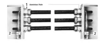
On any AC system, currents flowing in the centre conductor will induce small currents in the concentrically applied bonding wires and in the interlocked armour. For circuit ampacities up to and including 425 amps, these induced currents do not affect the cable ampacity and may be neglected. We recommend terminating the cables as follows: the bonding wires of all cables entering the equipment enclosure should be bunched and connected to the bonding screw of the terminal (2), the armour of each cable should be attached to the entry plate by means of an approved connector, and the entry plate should be aluminum or some other non-magnetic conducting material. Coordination with the facility’s grounding electrode conductor will further support fault clearing performance and reduce stray sheath currents.
From: Wire and Cable and Wiring Methods Handbook, Vol 3, The Electricity Forum


