


Industrial Electrical Power

Arc Flash Protection Explained
Arc flash protection mitigates electrical hazards through NFPA 70E compliance, IEEE 1584 arc flash studies, PPE selection, incident energy analysis, boundaries, and safe work practices for switchgear, MCCs, and energized maintenance.
What Is Arc Flash Protection?
Arc flash protection uses standards, PPE, and engineering controls to limit incident energy and protect workers.
✅ Perform IEEE 1584 arc flash study and incident energy calculations
✅ Apply NFPA 70E boundaries, PPE categories, and safe work practices
✅ Implement engineering controls: current limiting and arc-resistant gear
Arc flash protection is a critical safety measure designed to protect workers from the hazards of uncontrolled electrical explosions. An arc flash (AF) occurs when an electric arc creates a high-temperature explosion, releasing significant energy, which can cause severe injuries, including third-degree burns, electric shocks, and even death. Arc blast, a related phenomenon, involves the intense pressure wave from the explosion, which can cause additional injuries. The primary goal is to minimize the risk of arc flash occurring and ensure the safety of personnel working on or near electrical equipment. For additional context, resources explaining the circumstances that trigger an arc flash can help teams tailor hazard controls effectively.
Request a Free Training Quotation
Protecting Workers from Electrical Hazards: Key Strategies for Safety
Electrical hazards are a significant concern in any workplace that involves energized equipment. Among these, the risk of high-energy incidents from an electric arc presents serious dangers, including severe burns, electric shock, and physical injuries caused by the intense heat and pressure of an arc blast. To mitigate these risks, employers must develop comprehensive safety strategies, following industry standards like the NFPA 70E Standard for Electrical Safety in the Workplace. For a concise overview, see guidance on NFPA 70E arc flash principles to align training, procedures, and documentation.
Key Steps for Worker Protection from Electrical Hazards
To protect workers from potential incidents, the first step is a thorough risk assessment of the electrical system. This involves identifying potential dangers, such as unintentional contact with energized circuit parts, and determining the likelihood of an electric arc incident. The assessment must include a review of electrical equipment, ensuring that protective devices are functioning properly and the system is adequately maintained. Reviewing the fundamentals of the arc flash hazard supports accurate system studies, labeling, and mitigation planning.
A critical part of the assessment is determining the approach boundaries, which are zones of varying risk levels. The limited approach boundary restricts how close unqualified personnel can get to energized parts, while the restricted approach boundary limits access to qualified workers wearing appropriate personal protective equipment (PPE). Beyond these boundaries, proper signage and training are essential for maintaining a safe distance from the hazard. Additional clarification on NFPA 70E approach boundaries helps supervisors brief both qualified and unqualified personnel effectively.
In addition to PPE, workers must follow established safe work practices, including lockout/tagout procedures, to avoid exposure to energized systems. Organizations should verify that procedures meet NFPA 70E arc flash requirements for establishing and maintaining an electrically safe work condition.
What Personal Protective Equipment (PPE) is Required?
Selecting the right PPE is vital for minimizing the risk of injury from electrical incidents. The NFPA 70E standard outlines various levels of PPE based on the incident energy levels workers may face. For lower risk situations, basic flame-resistant clothing, safety gloves, and face shields may suffice. However, higher-risk environments, particularly those where an arc blast is possible, require more advanced PPE, such as insulated gloves, arc-rated suits, and helmets with protective shields. Reference materials describing arc flash levels of protection can aid in selecting garments and face protection appropriate to incident energy.
The type of PPE selected depends on the specific working distance from the energized parts and the calculated energy exposure. Proper PPE is crucial for keeping workers safe, particularly within the AF boundary, where the risk of severe injury is highest. A catalog of arc flash safety equipment can also assist in specifying accessories such as hoods, balaclavas, and voltage-rated tools.
How Do You Determine the Arc Flash Boundary and Incident Energy Levels?
The AF boundary defines the distance from an energized part where the heat energy is high enough to cause a second-degree burn. This boundary is determined through calculations based on factors such as the system's voltage, available fault current, and the protective device's clearing time. Tools like IEEE 1584 are used to calculate these boundaries accurately.
Additionally, the working distance — the space between the worker and the equipment during operation — plays a significant role in minimizing risk. The further the worker is from the energized part, the lower the energy they are exposed to, reducing the likelihood of severe injury.
A well-documented risk assessment is essential for establishing these boundaries and determining which controls, both administrative and engineering-based, are needed to protect workers.
NFPA 70E Standards for Electrical Safety
The National Fire Protection Association (NFPA) developed the NFPA 70E Standard for Electrical Safety in the Workplace to provide guidelines for minimizing the dangers associated with energized work. This standard requires employers to identify potential hazards, establish approach boundaries, and ensure the proper selection and use of PPE.
Training is a major component of compliance with NFPA 70E. Workers must be educated on recognizing electrical hazards, understanding approach boundaries, and knowing how to safely interact with electrical equipment. The standard also mandates regular audits of electrical safety programs to ensure they are current and effective.
The NFPA 70E emphasizes that no one should work within the restricted approach boundary without the appropriate qualifications and protections, underscoring the importance of maintaining proper distance from energized parts.
How Do Engineering Controls Impact Worker Safety?
While PPE and administrative controls play a critical role, engineering controls offer another layer of protection. One effective method is designing an electrical system to minimize the risk of high-energy incidents. For example, circuit breakers, fuses, and protective relays can be installed to detect faults and interrupt the flow of electricity, reducing the likelihood of dangerous events.
Additional measures include installing barriers and insulation around live electrical parts to prevent accidental contact and using remote racking devices to allow operators to work at a safer distance. These engineering controls are critical for reducing the need for workers to come into close proximity with energized equipment.
Proper maintenance of the electrical system is also crucial to ensuring that protective devices operate as intended. Faulty or poorly maintained equipment increases the chance of an electric arc incident, which can have catastrophic consequences for workers.
Worker safety in environments involving energized electrical equipment requires a combination of risk assessment, PPE, and engineering controls. Following the NFPA 70E Standard for Electrical Safety in the Workplace, organizations can create a safe work environment by establishing approach boundaries, providing the correct PPE, and implementing engineering solutions to limit the danger of electrical incidents.
By remaining vigilant and adhering to safety standards, employers can significantly reduce the risk of injury or death from electric arc events and ensure that workers are protected in hazardous conditions.
Related Articles
Test Your Knowledge About Electrical Protection!
Think you know Electrical Protection? Take our quick, interactive quiz and test your knowledge in minutes.
- Instantly see your results and score
- Identify strengths and areas for improvement
- Challenge yourself on real-world electrical topics
Latest IEP Content
What is Three Phase Electricity? Explained
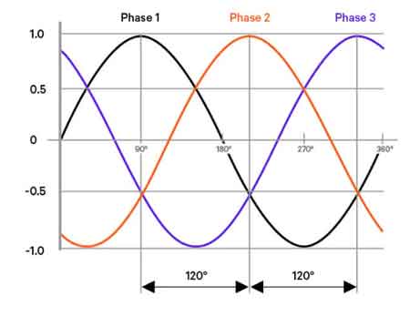
What is three phase electricity? A polyphase AC power system delivering three sinusoidal waveforms 120° apart, enabling balanced loads, efficient power distribution, higher power density, smoother torque in industrial motors, and reliable transmission via transformers.
What Is Three Phase Electricity?
A polyphase AC system with three 120° shifted waves for efficient, balanced power and motor performance.
✅ Three 120° phases reduce neutral current and voltage ripple
✅ Smaller conductors, lower losses, efficient transmission
✅ Constant torque in three-phase induction and synchronous motors
What is Three Phase Electricity? It is a method of delivering electrical power using three alternating currents that are each offset by 120 degrees. In a 3-phase power system, each current reaches its peak at different times within a cycle, ensuring that the power supply remains continuous and stable. This configuration allows for a more efficient and constant flow of power compared to single-phase power, where the current fluctuates between peak and zero. In three-phase systems, the power never drops to zero, resulting in constant power delivery to equipment and appliances. For foundational context on how transformers support three-phase distribution, this overview of electrical power transformers explains core functions and typical applications.
Electrical Transformer Maintenance Training
Substation Maintenance Training
Request a Free Training Quotation
In three-phase electrical systems, phase AC power plays a crucial role in maintaining efficient energy distribution across multiple circuits. Unlike single-phase systems, where only one phase circuit is used, three-phase systems have three separate alternating currents, each offset by 120 degrees, ensuring continuous power delivery. This structure allows phase power supplies to be more stable and effective in providing energy to large-scale industrial equipment. Each phase in the system contributes to a more balanced load, reducing the risk of power surges or failures, and ensures smoother operation of motors and machinery by distributing the electrical load more evenly. When facilities must supply single-phase loads from a three-phase feeder, a properly selected 3-phase to single-phase transformer helps maintain balance and minimize voltage drop.
What are the Advantages of Using Three Phase Electricity Over Single Phase Electricity?
The primary advantage of using 3-phase power over single-phase systems is its ability to transmit three times as much power using the same amount of current. In other words, it is far more efficient for delivering power over long distances and to larger loads. Additionally, three-phase systems provide smoother power delivery, which is essential for running motors and other industrial equipment. Unlike single-phase, where voltage dips can affect performance, three-phase provides a steady, constant power flow, making it ideal for heavy machinery. Moreover, because of its efficiency, three-phase systems reduce energy losses during transmission and distribution. Selecting among the different types of transformers ensures the distribution system meets efficiency and reliability goals for the intended load profile.
Where is Three Phase Electricity Commonly Used?
Three phase electricity is most commonly used in industrial and commercial settings where large amounts of power are required to operate equipment. In these environments, machinery often demands higher power levels than can be supplied by single-phase power. Three-phase is also commonly used in power systems for transmission and distribution, as it is more efficient for delivering power over long distances. Large office buildings, factories, and commercial complexes rely on three-phase power to operate elevators, HVAC systems, and industrial machinery. In contrast, most residential areas use single-phase systems since typical household appliances do not require the same high power levels. In residential neighborhoods, the last step-down is often a single-phase power transformer that feeds typical household circuits with safe, usable voltage.
How Does Three Phase Electricity Improve the Performance of Motors and Other Industrial Equipment?
Three-phase power improves the performance of motors and other industrial equipment by providing a more consistent flow of electrical energy. The alternating current (AC) in three-phase systems delivers power in such a way that it minimizes fluctuations in voltage, which can be problematic in single-phase systems. This results in smoother operation for motors and ensures that they run more efficiently. Additionally, the use of three-phase power allows for smaller, more cost-effective motor designs because they require less material to handle the same workload compared to motors designed for single-phase operation. For installations that must match motor voltage and grounding needs, a delta–wye transformer can provide isolation and appropriate line-to-neutral service without compromising efficiency.
What is the Difference Between Delta and Wye Configurations?
In 3-phase power supplies, the two most common configurations are delta and wye. In a delta configuration, the three conductors are connected in a closed loop, forming a triangle (or delta shape), and there is no neutral wire. This configuration is often used in transmission networks because it can handle higher voltages. In contrast, the wye (or star) configuration connects each phase to a central neutral wire, which allows for the provision of both 120 volts for lower-power applications and higher voltage for more significant loads. The wye configuration is commonly used in distribution networks and is preferred when both 120 volts and higher voltages are needed for different applications within the same power system. For a concise comparison of performance, grounding, and fault behavior, review this delta versus wye guide for practical design trade-offs.
Three phase electricity is a highly efficient and effective way to deliver power, especially in industrial and commercial applications. Its ability to provide constant power, support high loads, and deliver more energy with less loss makes it the preferred choice for many large-scale operations. Understanding the difference between single-phase systems and three-phase, along with configurations like delta and wye, is essential for optimizing power delivery in any AC power system. Where legacy equipment or grid constraints require a topology change, planned delta to wye conversion can enhance safety, fault detection, and service flexibility.
Related Articles
Hierarchy of Hazard Controls OSHA Explained
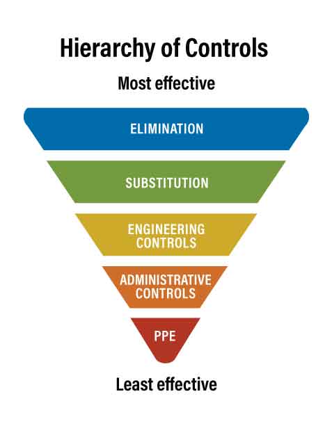
The hierarchy of hazard controls (OSHA) is a system that ranks safety measures to reduce workplace risks. It prioritizes elimination, substitution, engineering controls, administrative controls, and PPE to protect workers from hazards. This method improves compliance and injury prevention.
What is the Hierarchy of Hazard Controls (OSHA)?
The OSHA hierarchy of hazard controls is a ranked system used to minimize or eliminate workplace hazards. It follows a top-down approach:
✅ Eliminates or substitutes hazards at the source when possible
✅ Uses engineering and administrative controls to reduce exposure
✅ Relies on PPE only when other methods aren't feasible
Request a Free Training Quotation
The hierarchy of hazard controls, as outlined by OSHA, is a foundational concept in occupational safety, guiding employers and safety professionals in minimizing or eliminating workplace hazards. Developed by the National Institute for Occupational Safety and Health (NIOSH) and adopted by OSHA, this hierarchy ranks safety controls from the most effective to least effective, providing a structured approach to hazard management, including a combination of control methods, including administrative controls and personal protective equipment. For a practical guide to implementation, see our 7 Steps to Arc Flash Analysis, which integrates risk assessment and hazard mitigation strategies.
What are the Five Levels?
The hierarchy of hazard controls consists of five levels, each representing a different strategy for controlling hazards:
-
Elimination: Removing the hazard entirely from the workplace.
-
Substitution: Replacing a hazardous substance or process with a less hazardous one.
-
Engineering Controls: Isolating people from the hazard using physical changes to the workplace.
-
Administrative Controls: Changing work practices and procedures to reduce exposure to hazards.
-
Personal Protective Equipment (PPE): Using equipment to protect workers from exposure.
What is the Most Effective Hazard Mitigation Strategy?
The most effective level in the hierarchy of hazard controls is elimination. By completely removing the hazard, there is no risk of exposure to workers. For instance, automating a process to eliminate human interaction with hazardous machinery is a prime example of elimination. Learn how PPE fits into the hierarchy by browsing our Arc Flash PPE Category, including ratings and selection standards.
What are the Four Control Techniques that Comprise the Hierarchy of Controls?
The four primary control techniques within the hierarchy of controls are:
-
Elimination or Substitution: Removing the hazard or replacing it with something less harmful.
-
Engineering Controls: Implementing physical changes such as machine guarding or ventilation systems.
-
Administrative Controls: Modifying work practices, schedules, and procedures to limit exposure.
-
Personal Protective Equipment (PPE): Providing equipment like gloves, masks, and helmets to protect workers.
OSHA’s guidelines for hazard control are directly linked to 29 CFR 1910.147, which outlines lockout/tagout requirements for hazardous energy control.
How Does Elimination Differ from Substitution?
Elimination and substitution are the top two levels. Elimination involves completely removing the hazard from the workplace, ensuring no potential for exposure. Substitution, on the other hand, involves replacing a hazardous substance or process with one that poses a lower risk. For example, using water-based paints instead of solvent-based paints is a form of substitution. While both methods aim to reduce risk, elimination is more effective as it entirely removes the hazard. Explore the importance of engineering controls in arc flash scenarios by reviewing our Arc Flash Assessment Software page.
How Can Employers Implement the Hierarchy of Hazard Controls in Their Workplace?
Employers can implement the hierarchy through a systematic approach:
-
Conduct Hazard Assessments: Identify and evaluate hazards in the workplace.
-
Prioritize Controls: Apply the hierarchy, starting with elimination and substitution where possible.
-
Implement Engineering Controls: Install safety features such as machine guarding, ventilation, and noise control systems.
-
Develop Administrative Controls: Establish safe work practices, training programs, and preventive maintenance schedules.
-
Provide PPE: Ensure workers have access to and use the necessary personal protective equipment.
Employers should also foster a safety culture by involving employees in safety planning and continuously monitoring the effectiveness of implemented safeguards. To align with OSHA enforcement on control methods, check out our article on Is Arc Flash Analysis Required by OSHA.
Why is PPE Considered Least Effective in the Hierarchy?
PPE is considered the least effective control because it does not eliminate or reduce the hazard itself. Instead, it relies on the worker's consistent and correct use of the equipment to prevent exposure. PPE is often seen as a last line of defence, used when other measures are not feasible or sufficient. Additionally, PPE can be uncomfortable, impair job performance, and require regular maintenance and replacement.
How Does OSHA Enforce the Implementation?
OSHA enforces the implementation of the hierarchy through regulations, inspections, and citations. OSHA standards often mandate specific safety measures for hazardous chemicals, machinery, and work environments. During inspections, it evaluates whether employers are using the most effective measures to protect workers. Employers failing to comply with these standards may face citations and penalties. Additionally, it provides guidance, resources, and training to help employers understand and apply the safety measures.
The hierarchy of hazard controls, as outlined by OSHA, is a vital framework for ensuring workplace safety, guiding employers to protect workers from hazards effectively. By prioritizing measures from elimination to PPE, employers can create safer work environments and promote long-term health and safety. Understanding and implementing this hierarchy is essential for mitigating risks and safeguarding employees. For a broader understanding of regulatory alignment, see our section on NFPA 70E Arc Flash Training, which emphasizes compliance and safety best practices.
Contact us to learn more about our courses or request a free quotation.
Related Articles:
Battery Backup Explained
Battery backup delivers uninterruptible power to critical loads using UPS topology, inverter systems, and energy storage, providing voltage regulation, surge protection, and runtime during outages for sensitive equipment and industrial control circuits.
What Is Battery Backup?
A battery backup is an energy storage system that supplies temporary power to loads during outages, stabilizing voltage.
✅ Maintains critical load power during grid interruptions
✅ Provides surge protection, power conditioning, and voltage regulation
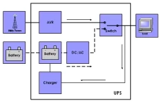
✅ Supports UPS topology: standby, line-interactive, or online
Battery backup is crucial in providing uninterrupted power for our devices and equipment during power outages. By understanding the different types of backup systems, battery capacity, and maintenance, you can make a well-informed decision to protect your home or business from unexpected power interruptions. So embrace the benefits of modern battery backup solutions and never be left in the dark again. For critical facilities, understanding how an emergency power supply integrates with battery backup can inform resilience planning.
We often take the constant supply of electricity for granted. However, power outages are unavoidable and can leave us scrambling for alternative energy sources. This is where battery backup solutions come into play, providing an essential lifeline in times of need. Many organizations adopt an uninterruptible power supply to ensure seamless continuity during brief outages.
Battery backup systems, or Uninterruptible Power Supply (UPS) systems, provide emergency power when the primary electrical supply fails. These systems can range from small portable power banks to larger installations that support businesses during power outages. A well-designed battery backup ensures that your essential devices and equipment stay up and running, minimizing downtime and preventing data loss. If you're new to the technology, this overview of what a UPS system is clarifies core components and typical use cases.
To choose the right UPS for your needs, consider factors such as the power requirements of your devices, the desired backup time, and your budget. An essential distinction to understand when selecting a backup solution is the difference between a UPS and a standard battery backup system. While both provide emergency power, a UPS offers a seamless transition without interruption to the connected devices. This feature is especially crucial for sensitive equipment like computers and servers. For a structured checklist, consult these tips for selecting a UPS system before finalizing your purchase.
Battery backup capacity plays a significant role in determining the duration of backup time during a power outage. Capacity is measured in ampere-hours (Ah) or watt-hours (Wh), which defines how much energy a battery can store. The larger the capacity, the longer it will last during a power outage. However, remember that larger-capacity batteries may require more space and come at a higher cost. To estimate runtime, review guidance on how long battery backups last under varying loads and conditions.
One of the most popular types of rechargeable batteries used in backup systems is the lithium-ion battery. These batteries boast a high energy density, allowing them to store more power in a smaller form factor. They also have a longer lifespan than traditional lead-acid batteries, making them an ideal choice for backup systems. Compatibility between lithium-ion modules and your UPS power supply should be verified for charging profiles and safety features.
Maintaining and prolonging the life of your battery backup involves a few essential steps. Please make sure that you store the batteries in a cool, dry place, away from direct sunlight and extreme temperatures. Regularly check the battery connections for any signs of corrosion and clean them if needed. Replacing your batteries according to the manufacturer's guidelines is crucial, as their efficiency decreases over time.
Solar power systems are increasingly integrated with battery backups as renewable energy sources become more prevalent. A solar battery backup stores energy generated by solar panels during the day, allowing you to tap into that stored power during a power outage or when energy demand is high. You can create a sustainable and eco-friendly power management system by combining solar power and battery storage. In hybrid systems, choosing an appropriate UPS uninterruptible power supply topology helps balance efficiency, transfer time, and protection.
Now that you understand battery backup solutions better, you can make an informed decision when selecting a system to safeguard your essential devices and equipment during power outages. You can ensure continuous power supply and minimize downtime by considering factors like UPS versus standard backup procedures, battery capacity, and type, and integrating solar power when possible.
Related Articles

Arc Flash PPE Requirements for NFPA 70E Compliance
Arc flash PPE requirements ensure workers wear appropriate protective gear, like arc-rated clothing and face shields, based on incident energy levels, minimizing injury risks.
What are Arc Flash PPE Requirements?
Arc flash PPE requirements are safety standards mandating specific protective equipment, such as arc-rated clothing, gloves, and face shields, based on the calculated incident energy exposure during electrical tasks, ensuring worker safety from arc flash hazards.
-
✅ Four PPE Categories: Classified by incident energy levels (4 to 40+ cal/cm²), each category dictates specific protective gear requirements.
-
✅ Determination Methods: PPE needs are identified through either detailed incident energy analysis or standardized task-based tables.
-
✅ Compliance Standards: Following NFPA 70E and CSA Z462 ensures proper PPE selection and enhances electrical safety.
Arc flash PPE requirements define the essential safety measures electrical workers must follow when performing energized tasks. From identifying hazard levels to selecting properly arc-rated (AR) gear, compliance with NFPA 70E guidelines ensures that the right protective clothing is worn for every situation. These standards help prevent serious injuries by aligning personal protective equipment (PPE) with the specific risks present in industrial and commercial electrical systems.
Request a Free Training Quotation
Selecting the right arc flash protection starts with understanding and following electrical PPE guidelines based on a thorough incident energy assessment of the work environment. This assessment helps determine the potential thermal energy a worker may be exposed to during an arc flash event. Based on this, employers must align task-based protection levels with the appropriate PPE hazard classification, ensuring that each job matches the correct safety equipment level. Organizations can minimize risk by identifying the required protective gear by task while meeting compliance requirements and safeguarding workers from preventable injuries. Use this arc flash PPE requirements chart to match clothing and gear with incident energy levels.
Understanding Hazards and PPE Levels
An arc flash is a dangerous electrical event that can release a violent burst of heat and pressure, causing severe injuries, burns, or even fatalities. To protect against this, NFPA 70E outlines four PPE levels based on incident energy, measured in cal/cm². Each level requires AR clothing and accessories designed to withstand a certain degree of thermal exposure.
PPE categories are based on the incident energy levels likely to be encountered during a task:
-
Category 1 (4 cal/cm²): Requires AR shirt and pants or coverall, face shield with wrap-around protection, hard hat, and voltage-rated gloves.
-
Category 2 (8 cal/cm²): This category adds an AR balaclava or flash hood and may require a heavier fabric weight.
-
Category 3 (25 cal/cm²): Requires a full suit, AR hood, gloves, and hearing protection.
-
Category 4 (40 cal/cm²): This category involves multi-layered suits designed for the highest exposure levels. For severe hazard scenarios, read about high-calorie suits on our 100 Cal Arc Flash Suit page.
Understanding the standards for minimum ratings ensures that protection is properly aligned with the electrical hazard classification for the task at hand. To better understand the different protection levels, explore our Arc Flash PPE Category page, which breaks down hazard levels and required gear. The NFPA 70E PPE requirements help define the proper protective equipment for various electrical tasks.
How Arc Flash PPE Requirements Are Determined
There are two acceptable methods under NFPA compliance for determining what PPE is required:
-
Incident Energy Analysis: A detailed engineering assessment calculates thermal energy at working distance. This method provides exact values for incident energy exposure levels and drives specific PPE requirements.
-
PPE Category Tables: Table 130.7(C)(15) and related charts define the PPE required for various tasks and equipment types, providing a simplified way to assess risk when a full engineering analysis is not performed.
Both approaches are valid and should be used according to the system's complexity and the precision needed for task-specific PPE.Selecting the right arc flash clothing is essential for compliance with NFPA 70E and CSA Z462 standards.
Key Electrical Safety Requirements
In addition to wearing the correct PPE, electrical workers must follow these requirements to ensure safety and legal compliance:
-
PPE must be AR and tested to meet or exceed the task's energy exposure.
-
Garments must be inspected and maintained regularly for damage, contamination, or wear that could reduce protection.
-
PPE must provide full body coverage, leaving no skin exposed during the task.
-
PPE should be clearly labeled with ratings in cal/cm².
-
Training must be provided to workers on the correct use and limitations of their PPE.
Employers are also responsible for maintaining a documented PPE selection process to ensure workers are properly outfitted based on the risk and job type. Explore the full range of arc flash safety gear required to minimize injuries from electrical incidents.
Best Practices for PPE Implementation
To meet and exceed requirements, companies should:
-
Integrate PPE selection into job safety planning.
-
Use risk-based PPE assessment tools when possible.
-
Maintain and audit PPE inventories to ensure availability and compliance.
-
Train staff regularly on PPE care, storage, and donning procedures.
In high-risk environments, incident energy suits and thermal-resistant garments offer additional protection, especially for workers operating close to energized components. Learn what goes into a fully compliant suit by checking out our in-depth page on the Arc Flash Suit, including face shields, gloves, and head protection. Learn how PPE performance is evaluated and rated for arc flash protection to ensure worker safety in high-risk environments.
Arc flash PPE requirements are not static checklists—they are living standards that evolve with each update of NFPA 70E. Organizations create a safer and more compliant electrical work environment by following proper PPE selection guidelines, understanding electrical hazard levels, and enforcing correct usage policies. Proper application of these rules not only satisfies compliance—it saves lives. Arc Flash Category 1 PPE includes basic protective clothing for tasks with low incident energy exposure.
Related Articles:
Explore our Arc Flash Training Programs or contact us to Request a Free Training Quotation for group safety sessions and PPE consultation.

Arc Flash PPE Clothing Explained
Arc flash PPE clothing provides workers with protective garments that shield them against electrical arc hazards. Arc-rated fabrics, insulated gear, and NFPA 70E compliance ensure safety, reduce burn risk, and meet the highest standards for workplace electrical safety.
What is Arc Flash PPE Clothing?
Arc flash PPE clothing refers to flame-resistant garments and protective gear designed to safeguard workers from arc flash (AF) events and electrical hazards.
✅ Provides flame-resistant protection against burns and heat energy
✅ Meets NFPA 70E, CSA Z462, and OSHA electrical safety standards
✅ Includes arc-rated shirts, pants, coveralls, gloves, and face shields
Request a Free Training Quotation
Arc flash PPE clothing is worn by electrical workers to protect them from injury and death. Electrical systems power industry, utilities, and critical infrastructure—but they also harbor the danger of electrical explosions. An AF is a violent electrical explosion caused when a low-impedance path allows high current to flow uncontrollably between conductors. These events release extreme heat, blinding light, and a blast pressure wave that can cause severe burns, shock, or fatalities. Workers who rely on arc flash PPE clothing must understand how it connects to the broader hazard, which is explained in detail in our arc flash overview.
Electrical workers rely on a multi-pronged safety approach that includes AF analysis, risk assessment, and the proper use of PPE clothing. This article examines the critical role of PPE, the various types of available clothing, and key factors to consider when selecting the right gear. When selecting protective garments, safety managers often reference NFPA 70E PPE requirements to ensure compliance and proper category selection.
Understanding the Threat: AF Hazards and Burn Injuries
The severity of an accident is shaped by several factors:
-
Available Fault Current: Higher current creates a more intense release of energy.
-
Arc Fault Current: The actual current during the arc, influenced by fault type and protective device clearing time.
-
Bolted Fault Clearing Time: Faster clearing reduces arc duration and incident energy.
-
Electrode Configuration: Phase-to-phase vs. phase-to-ground arrangements alter intensity.
-
Enclosure Type: Closed enclosures trap heat and pressure, making events more severe.
These factors determine incident energy, measured in calories per square centimetre (cal/cm²), which is used to specify PPE requirements. Engineers should use arc flash analysis and arc flash assessment resources to match PPE ratings with workplace hazards.
Electrical burns are unlike typical burns; they occur at extremely high temperatures over very short durations, often causing deep tissue injury even with minimal surface damage. Blast waves can also cause blunt trauma and flying shrapnel injuries.
The Role of Arc Flash PPE Clothing: A Shield Against the Blast
Arc flash PPE forms the last line of defense between the worker and the hazard. Constructed from FR materials tested to standards such as ASTM F1506 and ASTM F1959, garments resist ignition, self-extinguish, and provide protection against thermal energy. While no PPE eliminates all risk, properly selected and maintained personal protective equipment (PPE) greatly reduces the severity of injuries. For high-risk tasks, a 40 cal arc flash suit offers maximum protection against intense incident energy.
Types of Arc Flash PPE Clothing
Arc flash PPE clothing comes in various configurations to suit different risk levels and work environments. Here's a breakdown of the typical components:
-
Coveralls: These one-piece garments offer comprehensive protection for the torso, arms, and legs. They are available in varying protective ratings and are often the primary form of protection.
-
Jackets and Pants: Two-piece jackets and pants combinations offer flexibility and can be used in conjunction with other FR clothing for targeted protection.
-
Hoodies: These hooded garments offer additional protection for the head and neck, particularly important in tasks where overhead hazards are present.
-
Balaclavas: These balaclavas protect the head, face, and neck, leaving only the eyes exposed. They are often used in conjunction with other PPE, like helmets, for maximum facial protection.
-
Gloves: Specially designed gloves provide hand protection from the intense heat of an explosion. Selection is based on dexterity needs and rating.
-
Face Shields: These shields protect the face and eyes from the intense light and potential flying debris associated with an explosion.
Selecting the Right Arc Flash PPE: A Closer Look at Ratings
PPE is rated in cal/cm². Ratings must exceed the calculated incident energy, with a safety margin for error. NFPA 70E allows PPE selection by incident energy analysis or the PPE Category tables—both require consistent application.
Common ratings include:
-
4 cal/cm² – Basic protection for low-risk tasks
-
8 cal/cm² – General maintenance protection
-
12 cal/cm² – Medium-risk environments
-
25 cal/cm² – High-risk tasks with higher fault currents
-
40 cal/cm²+ – Highest protection, extreme hazard zones
It's crucial to select PPE with a rating exceeding the anticipated incident energy at the work location. A safety factor is often incorporated, meaning the chosen PPE rating should be higher than the calculated incident energy to account for potential inaccuracies in the AF analysis or unforeseen circumstances.
What to Wear Under Arc Flash Clothing?
When working in environments where arc flash PPE clothing is required, what you wear underneath is just as important as the outer protective layers. Here are key considerations:
-
Non-Melting Fabrics: Always wear natural fibres such as cotton, wool, or silk under arc flash PPE clothing. Synthetic fabrics, such as polyester or nylon, can melt under high temperatures, causing severe burns.
-
Avoid Multiple Layers of PPE: While layering can increase protection, it's crucial to ensure that underlayers are also flame resistant (FR). Adding non-FR layers can compromise safety.
-
Fit and Comfort: Ensure that the undergarments fit comfortably without restricting movement. This helps maintain focus and efficiency in the work environment.
How to Verify Arc-Rated Clothing?
Verifying arc-rated clothing is critical to ensure it provides the necessary protection in an AF event. Follow these steps to verify arc-rated clothing:
-
Check Labels: Arc-rated clothing must have a label indicating its arc rating, typically measured in calories per square centimetre (cal/cm²). Common ratings include 8 cal/cm², 25 cal/cm², and up to 40 cal/cm² for higher protection.
-
Look for Standards Compliance: Ensure the clothing meets standards such as ASTM F1506 and NFPA. These standards guarantee that the clothing has been tested and certified for AF protection.
-
Inspect the Condition: Regularly inspect arc-rated clothing for signs of wear and tear, including holes, fraying, or fading. Damaged clothing may not provide adequate protection and should be replaced.
What are the Rules for Arc Flash Clothing?
Compliance with rules and best practices for arc flash PPE clothing ensures maximum safety in the work environment. Here are some essential rules:
-
Wear Appropriate PPE: Select PPE clothing with the appropriate arc rating for the task at hand. Higher-risk environments may require clothing with ratings up to 40 cal/cm².
-
Follow Layering Guidelines: When layering clothing, ensure each layer is arc-rated. This increases overall protection without compromising safety.
-
Proper Fit: Clothing should fit well to provide full coverage and mobility. Loose or tight clothing can reduce protection and increase the risk of injury.
-
Regular Maintenance: Follow manufacturer guidelines for laundering and maintenance. Improper care can degrade the flame-resistant properties of the clothing.
How Should Clothing be Stored?
Proper storage of clothing extends its life and ensures it remains effective. Here are guidelines for storing PPE clothing:
-
Clean and Dry: Always store clothing clean and dry. Moisture and contaminants can degrade the fabric, reducing its protective capabilities.
-
Avoid UV Exposure: Prolonged exposure to sunlight or UV light can weaken the fabric. Store clothing in a cool, dark place to maintain its integrity.
-
Dedicated Storage Area: Use a dedicated storage area, such as lockers or sealed containers, to protect clothing from physical damage and contamination.
-
Inspect Before Storage: Check for any damage or wear before storing your item. Repair or replace damaged items to ensure they provide adequate protection when needed.
Why is Arc Flash PPE Clothing Important?
The right clothing is crucial for protecting workers from the severe consequences of incidents. Events can produce temperatures hotter than the sun's surface, causing severe burns, injuries, or even fatalities. Properly rated and maintained arc flash PPE clothing provides a critical barrier against these extreme conditions.
Beyond Ratings: Additional Considerations for PPE Selection
While ratings are a primary factor, several other considerations influence PPE selection:
-
Work Environment: The specific work environment and tasks can significantly influence the choice of PPE. For instance, activities involving potential contact with water may necessitate moisture-resistant clothing.
-
Dexterity and Comfort: Clothing should offer a balance between protection and worker comfort. Tasks requiring dexterity may necessitate lighter-weight or more flexible garments.
-
Kit Assembly: Many workers utilize kits containing a combination of coveralls, gloves, balaclavas, face shields, and safety glasses. Kits ensure all necessary PPE components are readily available for a specific rating.
-
Compatibility with Other PPE: PPE should be compatible with other required safety gear, such as hard hats, respirators, or safety harnesses, to ensure a complete and unobstructed layer of protection.
Maintaining Arc Flash PPE for Optimal Performance
The effectiveness of PPE hinges on proper maintenance and inspection. Here are some key practices:
-
Regular Visual Inspection: Before each use, workers should visually inspect their PPE for any signs of damage, melting, or contamination. Damaged PPE should be removed from service and replaced.
-
Cleaning: Follow manufacturer's instructions for cleaning garments to maintain their flame-resistant properties. Improper cleaning methods can compromise the effectiveness of the PPE.
-
Storage: Store PPE in a cool, dry, and clean location away from direct sunlight, heat sources, and chemicals that could degrade the material.
-
Replacement: Arc flash PPE clothing has a limited lifespan.
-
Follow manufacturer's recommendations for replacement based on wear and tear, exposure to heat or chemicals, or after an electrical explosion.
Shielding Workers for a Safer Tomorrow
Arc flash PPE clothing remains essential for worker safety, but it must be integrated into a comprehensive safety program that encompasses all aspects of the workplace. NFPA 70E training, analysis, and safe work practices complement the use of PPE to build a culture of electrical safety. Workers unsure about categories should review arc flash clothing for guidance.
Related Articles:
Transformer Sizing Explained
Transformer sizing ensures electrical transformers are properly matched to load demand, primary voltage, and secondary voltage. Correct sizing enhances efficiency, prevents overload, and ensures reliable operation in industrial power distribution.
What is Transformer Sizing?
Transformer sizing is the process of selecting the correct capacity and voltage ratings to meet electrical load requirements while ensuring safe, efficient, and reliable power delivery.
✅ Matches transformer kVA to load demand
✅ Ensures proper primary and secondary voltage
✅ Prevents overloads and efficiency losses
Electrical Transformer Maintenance Training
Substation Maintenance Training
Request a Free Training Quotation
Understanding transformer sizing is crucial for achieving optimal electrical system performance, ensuring safety, and maximizing efficiency. By considering factors such as capacity, kVA rating, load calculation, voltage ratio, primary and secondary windings, impedance matching, efficiency, temperature rise, and short-circuit current, it is possible to select the ideal size for a specific application. Working with an experienced electrical contractor or using a reliable calculator can help streamline the sizing process and ensure the most accurate results. When selecting typical transformer sizes, it is helpful to review the typical sizes used in various applications to ensure the proper selection of kVA.
Selecting the right-sized transformer for your electrical system is critical to ensuring efficiency, safety, and reliability. Proper sizing requires careful consideration of several factors, including capacity, kVA rating, load calculation, and voltage ratio. This article will examine these elements in detail and address some of the most frequently asked questions about selecting the correct unit size for various applications. For distribution-level applications, accurate sizing often involves selecting the appropriate distribution transformer to strike a balance between efficiency, safety, and system reliability.
One crucial aspect of selecting the right unit is understanding its capacity. This refers to the amount of power a unit can safely handle without overheating or causing system disruptions. Knowing the transformer's kilovolt-ampere (kVA) rating is crucial for determining the appropriate capacity. The kVA rating measures the transformer's apparent power, which combines both active and reactive power. This rating indicates the maximum power that a transformer can handle. Industrial load demands may require a properly sized three-phase transformer to handle balanced and unbalanced loads effectively.
The next step in the sizing process is a load calculation. It involves determining the total electrical load that the system or equipment requires to be powered by the unit. This can be calculated using a kVA calculator or by consulting an experienced electrical contractor. Load calculation is crucial to ensure the device can supply sufficient power without overloading, which could lead to equipment failure and even hazardous situations.
Voltage ratio, another essential factor, refers to the ratio of the input voltage (primary voltage) to the output voltage (secondary voltage) in the unit. The voltage ratio is directly related to the number of turns in the primary and secondary windings, which affects performance. Therefore, selecting the appropriate voltage ratio based on the equipment's power requirements is essential to avoid over- or under-voltages. Utility engineers often reference substation transformers when determining appropriate sizing for high-voltage to medium-voltage conversions.
The primary and secondary windings play a vital role in transformer sizing. This is because primary windings are connected to the power source, while secondary windings supply power to the load. Therefore, ensuring the correct number of turns in each winding based on the voltage ratio is crucial for optimal performance and efficiency.
Impedance matching is a vital factor when sizing transformers. It involves ensuring that the impedance of the primary winding matches the impedance of the secondary winding to avoid power losses and ensure efficient power transfer between the input and output circuits.
Efficiency is another critical aspect to consider when selecting a unit size. Efficiency is determined by the ratio of its output power to its input power. A higher efficiency indicates less power is lost in heat, resulting in better performance and reduced operating costs.
The temperature rises and the short-circuit current also influence the sizing process. The temperature rise increases due to the handling load. Excessive temperature rise can cause insulation degradation and reduce lifespan. On the other hand, short-circuit current refers to the maximum current that flows through the unit when a short circuit occurs. Proper sizing helps to ensure that the device can withstand the effects of short-circuit currents without damage.
Frequently Asked Questions
How do you calculate the correct size of a transformer?
Calculating the correct size of a unit involves determining the load voltage, the load required, the kVA rating, and the voltage ratio. An electrical contractor or kVA calculator can help you with these calculations. Understanding construction is vital to proper sizing, and our guide on transformer components explains the role of cores, coils, and windings.
What factors should be considered when selecting a size?
When selecting a transformer size, several factors must be considered, including capacity, kVA rating, load calculation, voltage ratio, primary and secondary windings, impedance matching, efficiency, temperature rise, and short-circuit current.
What are the consequences of choosing an incorrectly size?
Consequences of choosing an incorrectly sized transformer include reduced efficiency, increased energy costs, potential damage to equipment, and safety hazards. In power distribution networks, selecting the correct medium-voltage transformer size ensures both operational safety and cost efficiency.
How do primary and secondary winding voltages affect sizing?
Primary and secondary winding voltages affect sizing by influencing the voltage ratio, which determines the number of turns in the windings.
How does impedance matching impact sizing?
Impedance matching impacts sizing by ensuring efficient power transfer between the input and output circuits, thus preventing power losses and enhancing overall performance.
How does efficiency influence size selection?
Efficiency influences size selection as higher-efficiency units can handle more power with less energy loss, resulting in better performance and reduced operating costs.
How does the temperature rise and short-circuit current affect sizing?
Temperature rise and short-circuit current affect sizing because excessive temperature rise can cause insulation degradation, reducing the lifespan. In contrast, proper sizing ensures the device can withstand short-circuit currents without damage.
Please pay close attention to the abovementioned factors to ensure the correct unit size is chosen. Also, consulting with an experienced electrical contractor or using a transformer sizing calculator is highly recommended to make the most informed decision.

Green Energy
Green energy integrates renewable electricity from solar, wind, and hydro into smart grids using power electronics, advanced inverters, energy storage, and grid automation to enhance reliability, power quality, and low-carbon transmission.
What Is Green Energy?
Green energy is renewable electricity from solar, wind, and hydro, using power electronics, smart grids, and storage.
✅ Power electronics and inverters convert PV DC to grid-synchronous AC.
✅ Smart grids manage variable renewables with SCADA, EMS, and demand response.
✅ Energy storage and microgrids enhance reliability, power quality, and resilience
Green energy, often synonymous with renewable energy, has gained significant attention in recent years as the world seeks to reduce its reliance on fossil fuels, minimize environmental damage, and promote a more sustainable future. This shift towards clean energy resources helps reduce greenhouse gases and air pollutants and plays a vital role in conserving non-renewable resources and promoting efficiency.
There are several green energy sources, each with unique benefits and challenges. Solar energy, one of the most popular renewable sources, harnesses the sun's energy to generate electricity. Solar panels, commonly installed on rooftops or in solar farms, convert sunlight into electricity for homes and businesses. As solar technology advances, solar system installation costs have dropped significantly, making it more accessible to individuals and communities alike. For homeowners, adopting comprehensive strategies is easier when using resources like energy management frameworks that track consumption and optimize production.
Wind energy, another widely recognized green energy source, is generated by converting the kinetic energy of wind into electricity using wind turbines. Large wind farms can produce significant energy, often enough to power entire communities or cities. However, wind power's effectiveness depends on the location and weather conditions, as wind speeds must be sufficient to generate electricity consistently. To mitigate variability, utilities often integrate energy management systems to balance wind output with demand forecasts.
Hydropower, one of the oldest renewable green energy sources, utilizes the movement of water to generate electricity. Dams and hydroelectric power stations convert the potential energy of water stored at a height into electricity, providing a stable and reliable source of energy. However, the construction of dams can lead to environmental concerns, such as habitat disruption and changes to local ecosystems. In facilities adjacent to dams, building energy management systems can tune loads to align with scheduled releases for greater efficiency.
Biomass energy is derived from organic materials, such as plants and animal waste, which can be burned directly for heat or converted into biofuels, such as ethanol and biodiesel. This form of green energy can help reduce waste and greenhouse gas emissions. However, the large-scale production of biomass crops can compete with food production and lead to deforestation. Modern plants deploy energy management controls to maintain combustion efficiency and emissions performance across feedstock variations.
Geothermal green energy taps into the Earth's natural heat by capturing steam or hot water from underground reservoirs to generate electricity. This clean energy source has a minimal environmental impact, but its availability is limited to areas with specific geological conditions. In buildings served by district geothermal, integrating building automation enables coordinated HVAC setpoints and thermal storage strategies.
Green energy offers numerous environmental benefits, such as reducing greenhouse gas emissions, air pollution, and dependence on finite energy resources like coal, oil, and natural gas. By transitioning to renewable green energy sources, we can significantly reduce our carbon footprint and mitigate the effects of climate change. Additionally, green energy technologies can create new job opportunities and stimulate economic growth.
However, there are also some drawbacks to green energy sources. For example, intermittency issues can arise with solar and wind power, depending on weather conditions. Moreover, the initial investment for installing renewable energy systems can be high, although costs have decreased recently.
Individuals can contribute to the growth of green energy by installing solar panels in their homes, using energy-efficient appliances, and supporting policies that encourage the adoption of renewable energy sources. The cost of switching to green energy varies depending on the technology, location, and government incentives available.
Emerging trends in green energy technology include advancements in energy storage solutions, such as batteries and hydrogen storage, which can help address intermittency issues. Furthermore, innovations in smart grids and microgrids allow for better integration and management of renewable sources. These improvements are complemented by advanced energy management analytics that forecast loads and orchestrate distributed assets.
Government policies play a critical role in supporting the adoption of green energy. For example, incentive programs, tax credits, and subsidies can help lower the cost of renewable power installations, making them more accessible to consumers. Additionally, regulations and targets for reducing greenhouse gas emissions and increasing the use of renewable sources can drive further investment in green energy technologies. Organizations can accelerate adoption by instituting a formal energy management program that aligns incentives, metering, and continuous commissioning efforts.
Embracing green energy sources is crucial for building a sustainable and cleaner future. By understanding the different types of green energy and their environmental benefits, individuals and governments can make informed decisions to promote adopting green energy solutions.
As the United States and other countries worldwide continue to invest in renewable technologies, the production landscape is rapidly changing. This transition to green energy sources is essential to reducing our reliance on fossil fuels, minimizing the environmental impacts of energy production, and ensuring a sustainable future for generations to come.
Increasing public awareness and education is one way to promote green energy further. By informing citizens of the benefits and potential drawbacks of different renewable sources, we can foster a more informed and engaged public, encouraging individuals to make greener choices in their daily lives.
Community-based green energy renewable projects can also help facilitate the widespread adoption of green energy. These projects, such as community solar gardens or small-scale wind farms, allow individuals who may need more resources or space to install their renewable systems to benefit from clean energy production. In addition, by pooling resources and sharing the benefits, communities can work together to create a more sustainable future.
Advancements in green energy technologies will also play a significant role in increasing the adoption of renewable sources. As researchers and engineers continue to develop more efficient and affordable technologies, the barriers to entry for green energy will continue to decrease. In addition, innovations in materials science, such as the development of more efficient solar cells or improvements in wind turbine design, can lead to significant gains in the performance of renewable systems.
Finally, international cooperation and collaboration will be essential in advancing green energy on a global scale. Climate change and environmental degradation do not respect national borders; thus, a united effort is necessary to combat these challenges. By sharing knowledge, resources, and technology, countries can work together to promote the adoption of green energy and build a more sustainable future for all.
Green energy is an essential component of a sustainable, environmentally responsible future. Investing in renewable technologies, supporting government policies, and engaging in individual and community-based efforts can help drive the adoption of green energy sources and ensure a cleaner, healthier world for future generations. With continued innovation, increased public awareness, and international collaboration, the promise of a green energy revolution becomes more attainable each day.
Related Articles
IEP News
IEP Media


IEP Articles From ET Magazine

Compatibility Issues with Generator-Backed Power Systems
While both UPS systems and generators serve as safeguards against power disruptions, their integration isn't always seamless. Understanding these compatibility concerns is crucial for ensuring reliable backup power and avoiding damage to sensitive equipment.
Visit Our UPS Systems Study Course
Voltage and Frequency Stability
Generators, particularly smaller portable models, may not provide the same level of voltage and frequency stability as utility power. Line-interactive UPS units are designed to operate within a specific input voltage and frequency range. Wide fluctuations outside these tolerances can trigger the UPS to switch to battery frequently, draining reserves and potentially causing premature battery wear.
Synchronization Issues
When power from a generator is restored, there may be a phase shift or momentary mismatch in frequency compared to the UPS output. This lack of synchronization can lead to a disruptive transfer process, potentially causing a brief outage for the connected equipment.
Harmonic Distortion
Generators, especially lower-quality models or those under non-linear loads, can introduce harmonic distortion into the electrical waveform. This 'noise' in the power supply can affect the operation of sensitive electronics connected to the UPS and degrade overall power quality.
Strategies for Improved Compatibility
UPS Selection: Look for line-interactive UPS models with wider input voltage and frequency tolerance ranges. Some may offer a 'generator mode' that accommodates greater fluctuations.
Generator Quality: Whenever possible, opt for generators with better voltage regulation and lower harmonic distortion. Inverter-based generators generally provide cleaner output than conventional models.
Generator Sizing: Overloading a generator can lead to unstable output. Ensure the generator's capacity comfortably exceeds the anticipated load demand.
Isolation Transformers: In specific cases, an isolation transformer between the generator and UPS can improve compatibility by filtering out some harmonic distortion and stabilizing the voltage.
Double-Conversion UPS: A More Forgiving Solution
While the steps outlined above can improve compatibility, double-conversion online UPS systems are inherently better suited for use with generators. Here's why:
Complete Isolation: Double-conversion UPS units continuously convert incoming AC to DC and back to AC, creating a clean and regulated output regardless of generator power quality.
Wider Tolerance: These UPS systems often have wider acceptable input voltage and frequency windows, handling generator fluctuations without issue.
Considerations When Connecting a Line-Interactive UPS to a Generator
UPS Runtime: If frequent generator power deviations cause the UPS to switch to battery often, runtime will be reduced for longer outages. Assess the stability of your generator to gauge this risk.
Load Sensitivity: Less critical equipment can often tolerate generator-powered line-interactive UPS output. Highly sensitive systems might warrant a double-conversion UPS for cleaner backup power.
Neutral Bonding: Proper grounding practices are vital, especially in a generator-UPS setup. Improper neutral bonding can lead to dangerous stray currents and equipment damage.
Additional Tips
Consult Manufacturer Recommendations: Always refer to the instructions for your specific UPS and generator for guidance on compatibility and best practices.
Regular Testing: Periodically test the switchover between the generator and UPS power under load. This helps identify potential issues and ensures backup systems work as intended when needed.
Integrating line-interactive UPS systems with generators requires attention to power quality and synchronization. While choosing suitable equipment and implementing mitigation strategies improves compatibility, double-conversion UPS systems offer superior inherent resilience against generator power fluctuations. Organizations can design robust power protection schemes that ensure uninterrupted operation even during extended outages by carefully considering backup power needs and equipment sensitivity.

Line-Interactive UPS in Scalable IT Infrastructure
In the evolving landscape of IT infrastructure, reliable and flexible power solutions are paramount. Scalable line-interactive Uninterruptible Power Supply (UPS) systems provide an essential service to growing IT networks by adapting to increasing power demands without the need for complete system overhauls. This adaptability ensures that businesses can expand their IT capabilities while maintaining protection against power interruptions and fluctuations.
Visit Our UPS Systems Study Course
Scalability and Its Importance
Scalability in a UPS context refers to the ability to increase the UPS capacity to handle higher loads as demand grows. This is particularly crucial for businesses experiencing rapid growth or those planning for future expansion. The scalable nature of certain UPS systems allows for the addition of more power modules within the same infrastructure, thereby accommodating growth without significant downtime or large-scale replacements.
Advantages of Scalable UPS Systems
Cost Efficiency: Implementing a scalable UPS system is cost-effective over time. Businesses can invest in what they need today, knowing that the system can grow with their requirements. This staged investment helps manage cash flow better compared to investing in a large system upfront.
Reduced Downtime: The modular design of scalable UPS systems allows for expansions and upgrades to be performed with minimal impact on ongoing operations. This is vital for maintaining high availability and reducing the risk of downtime during upgrades.
Enhanced Flexibility: With scalable systems, IT managers can customize the UPS to meet the exact needs of their network, adjusting for power load, redundancy requirements, and runtime. This flexibility also extends to maintenance and servicing, as individual modules can be serviced or replaced without shutting down the entire system.
Long-term Reliability: Scalable UPS systems are designed to accommodate future technology changes and increases in demand. This foresight ensures that the UPS system remains reliable and effective over a longer period, thereby protecting the IT investment as the business landscape evolves.
Implementation Considerations
When planning to implement a scalable UPS system, several factors need to be considered:
Initial Assessment: Accurately assessing current power needs and future growth projections is crucial to selecting a UPS with appropriate scalability options.
Space Planning: Scalable UPS systems require strategic placement as expansions will necessitate additional space. Planning for this during the initial setup phase is essential.
Budget Allocation: While the initial cost of a scalable UPS may be higher than that of a fixed-capacity system, the long-term savings and benefits often justify the investment.
In the dynamic landscape of IT infrastructure growth, the scalability of line-interactive UPS systems presents a significant advantage. By enabling organizations to match power protection to current needs while retaining expansion capabilities for the future, scalable UPS solutions ensure reliable power, optimized investment, and minimal disruptions during inevitable periods of growth.
Scalable line-interactive UPS systems represent a smart choice for growing IT networks, offering a flexible, reliable, and cost-effective solution that grows alongside business needs. As IT infrastructure becomes increasingly critical, investing in a UPS system that can adapt to changing demands is an essential strategy for future-proofing IT operations and ensuring continuous power protection. This approach not only supports operational continuity but also aligns with the strategic growth objectives of modern businesses.

Securing Critical Infrastructure: The Role of Line-Interactive UPS
UPS (uninterruptible power supply) systems are essential for protecting critical infrastructure in healthcare and finance. They provide backup power in the event of a power outage, ensuring that sensitive equipment and data are protected. Line-interactive UPS systems are a popular choice for these applications, offering a number of advantages over other types of UPS systems.
Visit Our UPS Systems Study Course
Benefits of Line-Interactive UPS Systems
Line-interactive UPS systems offer a number of benefits over other types of UPS systems, including:
Lower cost: Line-interactive UPS systems are typically less expensive than other types of UPS systems, making them a more cost-effective option for businesses on a budget.
Smaller size: Line-interactive UPS systems are also smaller than other types of UPS systems, making them ideal for applications where space is limited.
Lower maintenance: Line-interactive UPS systems require less maintenance than other types of UPS systems, making them a more hassle-free option for businesses.
Types of Line-Interactive UPS Systems
There are two main types of line-interactive UPS systems: standby and online. Standby UPS systems only provide power when the primary power source fails, while online UPS systems provide continuous power, even during power outages.
Standby UPS systems are typically less expensive than online UPS systems, but they also offer less protection. They are a good choice for applications where the risk of a power outage is low.
Online UPS systems are more expensive than standby UPS systems, but they offer more protection. They are a good choice for applications where the risk of a power outage is high, such as hospitals and data centers.
Performance of Line-Interactive UPS Systems
The performance of a line-interactive UPS system is determined by a number of factors, including:
Power output: The power output of a UPS system is measured in VA (volt-amps). It must be sufficient to power the equipment it is protecting.
Runtime: The runtime of a UPS system is the amount of time that it can provide power during a power outage. The runtime of a UPS system is determined by the size of its battery.
Efficiency: The efficiency of a UPS system measures how much power it loses during conversion. A more efficient UPS system will lose less power and be more cost-effective to operate.
Technical Considerations
There are a number of technical considerations that must be taken into account when selecting a line-interactive UPS system, including:
Input voltage: The input voltage of a UPS system is the voltage of the power source that it is connected to. The input voltage of a UPS system must be compatible with the voltage of the power source.
Output voltage: A UPS system's output voltage is the power it supplies to its connected equipment. It must be compatible with the voltage of the equipment it is protecting.
Frequency: The frequency of a UPS system is the rate at which it converts power. The frequency of a UPS system must be compatible with the frequency of the power source.
Across the healthcare and financial sectors, where the consequences of downtime range from inconvenient to life-threatening or financially devastating, line-interactive UPS systems play a silent but vital role. Their ability to provide clean power, instant backup, and facilitate safe shutdown procedures acts as an indispensable insurance policy for critical infrastructure. As power grids evolve and technologies advance, the integration of UPS protection will remain deeply intertwined with maintaining resilience and reliable service delivery in these vital sectors.
Battery Advancements and the Impact on Line-Interactive UPS
Advancements in Battery Technology and Their Impact on Line-Interactive UPS
Line-interactive uninterruptible power supply (UPS) systems play a crucial role in ensuring power continuity for sensitive electronic equipment. Serving as a safeguard against power disruptions, these systems seamlessly switch to battery backup during outages, preventing data loss, equipment damage, and downtime. Recent advancements in battery technology, particularly lithium-ion batteries, have significantly influenced the capabilities and performance of line-interactive UPS systems.
Visit Our UPS Systems Study Course
Lithium-ion: The Emerging Choice
Lithium-ion (Li-ion) batteries, widely known for their use in laptops and electric vehicles, are increasingly finding their way into UPS systems. Here's how they stand out:
Higher Energy Density: Li-ion batteries pack more energy into a smaller and lighter form factor compared to lead-acid counterparts. This translates to space-saving UPS units or more runtime within the same footprint.
Longer Lifespan: Li-ion batteries boast more charge/discharge cycles than lead-acid batteries. This could mean less frequent battery replacements over the lifetime of the UPS system, reducing maintenance costs.
Faster Recharge Times: Li-ion batteries generally recharge faster, contributing to quicker recovery times between outages.
Efficient Operation: Reduced internal resistance leads to greater efficiency in charging and discharging, thus minimizing energy losses.
Considerations and Trade-offs
Cost: Currently, Li-ion-based UPS systems typically carry a higher initial price tag compared to those using lead-acid batteries. However, the total cost of ownership over time may be comparable or even favorable due to their longevity and lower maintenance.
Management Complexity: Li-ion batteries sometimes require more sophisticated battery management systems (BMS) for safe and optimal operation.
Safety: Certain Li-ion chemistries, if mishandled, have greater potential for thermal runaway than traditional lead-acid batteries. Reputable manufacturers prioritize robust design and safety measures in their Li-ion UPS units.
Other Battery Advancements
Enhanced Lead-Acid Batteries: Developments like Thin Plate Pure Lead (TPPL) and Absorbed Glass Mat (AGM) technologies have improved lead-acid battery performance in areas like cycle life, recharge times, and tolerance to temperature fluctuations.
Alternative Chemistries: Flow batteries, sodium-ion batteries, and more offer unique characteristics potentially relevant to specific UPS use cases.
The Impact on Line-Interactive UPS
The integration of advanced battery technologies into line-interactive UPS designs brings about notable implications:
Compact Designs: Smaller batteries open up possibilities for more streamlined and space-efficient line-interactive units, particularly valuable in edge computing and cramped network closets.
Increased Reliability: Longer battery lifespan and resilience towards environmental conditions enhance UPS system reliability overall.
Extended Runtimes: Depending on the application, advanced batteries may unlock longer backup times on smaller line-interactive units.
Eco-Friendliness: Li-ion batteries have the potential for greater recyclability than lead-acid options, minimizing environmental impact at end-of-life.
Choosing the Right Battery Technology
The optimal battery choice for your line-interactive UPS depends on several factors:
Criticality of the Load: For highly critical applications, the added longevity and performance of Li-ion batteries often justify the cost.
Space Constraints: Where installation space is extremely limited, the compactness of Li-ion solutions becomes a major advantage.
Environmental Conditions: If the UPS is in a less temperature-controlled environment, the robustness of newer lead-acid technologies or some advanced options might be preferable.
Budget: If the initial purchase cost is the primary driver, a traditional lead-acid line-interactive UPS may still be the most practical solution.
The advancements in battery technology are transforming the landscape of line-interactive UPS systems, enhancing their efficiency, reliability, and sustainability. As lithium-ion batteries continue to evolve and decrease in cost, they are expected to become the standard choice for new UPS installations, offering significant advantages over traditional battery technologies. Organizations looking to upgrade or install new UPS systems should consider the long-term benefits of lithium-ion batteries, despite the initial higher investment, to ensure reliable and efficient power backup solutions.
FREE EF Electrical Training Catalog
Download our FREE Electrical Training Catalog and explore a full range of expert-led electrical training courses.

- Live online and in-person courses available
- Real-time instruction with Q&A from industry experts
- Flexible scheduling for your convenience
Sign Up for Electricity Forum’s Electrical Protection Newsletter
Stay informed with our FREE Electrical Protection Newsletter — get the latest news, breakthrough technologies, and expert insights, delivered straight to your inbox.