Faraday's Law Explained

By R.W. Hurst, Editor


Faraday’s Law describes electromagnetic induction, where changing magnetic fields generate electricity. Discovered in 1831 by Michael Faraday, it revealed how magnetism produces electric current and became the foundation of modern electrical science.


What is Faraday’s Law?

Faraday's Law is a fundamental principle of electromagnetism describing how a changing magnetic field induces an electromotive force (emf) in a conductor. The law: 

✅ Explains electromagnetic induction and induced current

✅ Is essential for transformers, generators, and electric motors

✅ Is the foundation of modern physics and electrical engineering

For a deeper look at the mathematics, mechanisms, and engineering uses, see our detailed guide on Faraday’s Law of Induction."


Michael Faraday, the Inventor of Faraday’s Law

In 1831, Michael Faraday performed experiments with coils of wire, magnets, and galvanometers. He observed that when a magnet was moved through a coil, or when the magnetic field around the coil was changed, a current was generated.

Faraday’s Law proved that electricity could be produced directly from magnetism — a revolutionary concept at the time. Faraday’s experiments were deceptively simple but profoundly important, showing that energy could be converted from one form (mechanical motion of the magnet) into another (electric current). 


Theoretical Context

Faraday’s Law provided one of the first clear demonstrations that electricity and magnetism are not separate forces but part of the same phenomenon. This insight was later formalized by James Clerk Maxwell, whose Maxwell’s equations mathematically unified electromagnetism.

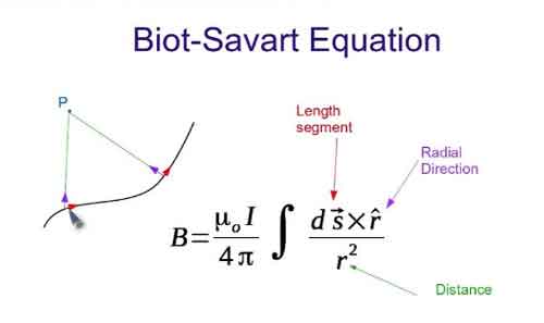
Alongside Ampère’s Law and the Biot–Savart Law, Faraday’s Law gave scientists a new framework to describe the invisible forces of nature. It also introduced the idea of fields, regions of influence surrounding magnets and electrical charges, which became central to modern physics. Read our article titled: Who Invented Electricity for more information about the foundation of electricity.


Understanding Electromagnetic Induction

Faraday’s Law showed that induction can occur in several ways:

  • By moving a conductor through a magnetic field

  • By changing the strength of a magnetic field

  • By altering the orientation or size of the conductor’s loop in the field

In each case, the result is the same: a changing magnetic flux produces an EMF. The direction of the induced current is explained by Lenz’s Law, which states that the induced current always opposes the change that created it, ensuring energy conservation.

The principle of electromagnetic induction is the basis for the operation of various electrical devices, including:

  • Generators: These devices convert mechanical energy into electrical energy by rotating a coil within a magnetic field, causing the magnetic flux to change and inducing an EMF in the coil.

  • Transformers: Transformers work on the principle of mutual induction, where a changing current in the primary coil produces a varying magnetic field, which in turn induces an EMF in the secondary coil.

  • Induction motors: In these motors, a changing magnetic field is created by the stator, inducing an EMF in the rotor conductors, which generates a current that interacts with the magnetic field to produce torque and drive the motor.


Coils, Flux, and Electrodynamics

Faraday’s induction experiments showed that the induced voltage in a coil is equal to the rate of change of magnetic flux through it. This relationship depends on several factors, including the magnetic field strength, the loop area, and the number of turns in the coil. In fact, the induced EMF is proportional to the rate at which a coil of wire cuts across magnetic field lines, meaning that more turns in the coil increase the overall flux linkage.

From the perspective of electrodynamics, this effect illustrates how charges respond to forces within a conductor. The Lorentz force explains why electrons move when exposed to a changing field, while a time-varying field generates a non-conservative electric field that sustains induction. These principles are embedded in the Maxwell–Faraday equation, which extends Faraday’s insight into the framework of Maxwell’s equations.

Faraday also noted that induction is not limited to mutual coupling between separate coils. The principle of self-induction arises when a coil’s own changing current produces an induced EMF opposing the original change. This phenomenon became central to the design of inductors and transformers.

Ultimately, the legacy of Faraday’s Law extends to our understanding of electromagnetic waves. By linking induction with Maxwell’s field theory, Faraday’s Law explains how time-varying fields generate waves that propagate through space — a concept that underpins modern communications and physics.


Why Faraday’s Law Mattered

At the time of its discovery, electricity was known mainly from batteries and static experiments. Faraday’s Law proved that electricity could be generated in continuous and controlled ways. This breakthrough opened the door to inventions that would transform society, from power generation to communication technologies.


Everyday Applications of Faraday’s Law

The importance of Faraday’s Law extends far beyond the laboratory. It forms the basis of countless technologies, including:

  • Electric generators – converting mechanical energy into electrical power.

  • Transformers – enabling efficient power transmission over long distances.

  • Induction motors – powering everything from industrial machines to household appliances.

  • Wireless charging systems – transferring energy without physical connections.

  • Magnetic storage and security – used in swipe cards and sensors.

  • Induction heating and cooktops – converting magnetic energy into heat for practical use.

  • Eddy current braking – providing non-contact braking in trains, amusement rides, and industrial systems by inducing currents that resist motion.

  • Inductors in circuits – storing energy in magnetic fields and controlling current in electrical systems.

  • Wireless energy transfer in EVs – enabling electric vehicles to charge without plugs using electromagnetic induction.

These applications show how Faraday’s 19th-century experiments continue to power the 21st-century world.


Faraday’s Legacy

Faraday’s Law was not just a scientific milestone but also a turning point for technology and industry. Without his insights, there would be no electric power grids, no telecommunications as we know them, and no modern electronics.

The law also highlighted an important principle: that simple experiments can lead to world-changing insights. With little formal education, Faraday reshaped science and technology, showing that careful observation and curiosity could unlock nature’s secrets.

Faraday’s Law remains one of the most important discoveries in physics. By revealing that changing magnetic fields could create electricity, it provided the foundation for modern electrical engineering, industrial power systems, and everyday devices.

Faraday’s Law stands as a reminder that the forces of nature — magnetism, electricity, and motion — are deeply interconnected. Faraday’s insight into electromagnetic induction continues to shape the modern world, demonstrating that a discovery made nearly two centuries ago remains a vital force in our lives today.


Frequently Asked Questions


What did Faraday’s Law prove?

Faraday’s experiments with coils and magnets in 1831 proved that a changing magnetic field can induce an electromotive force (EMF) in a conductor. This showed that electricity can be generated from magnetism, a discovery that revolutionized science and technology.


Why is Faraday’s Law important today?

Faraday’s Law is the foundation of electrical power generation and transmission. It explains how generators, transformers, and induction motors work, making it essential to modern energy systems, communication technologies, and countless everyday devices.


How does Faraday’s Law relate to Maxwell’s equations?

Faraday’s Law was later formalized in Maxwell’s equations as the Maxwell–Faraday equation, which shows that a changing magnetic field produces an electric field. This unification confirmed that electricity and magnetism are two aspects of the same force.

Related News

Nominal Voltage and AC and DC Standards

Nominal voltage is the standard voltage level assigned to electrical equipment or systems for identification. It helps ensure compatibility, performance, and safety across devices without indicating actual operating voltage, which may vary slightly.


What is Nominal Voltage?

Nominal voltage refers to the labelled voltage value of an electrical system or device.

✅ Represents standard system voltage, not an  exact measurement

✅ Helps match equipment compatibility and safety standards

✅ Common in power distribution, residential, and industrial systems


Nominal voltage (NV) is a vital aspect of electrical systems, serving as a reference point for designing, manufacturing, and testing equipment. Additionally, it affects the performance, efficiency, and safety of electrical systems, with voltage regulation ensuring that voltage levels (V) remain within acceptable tolerances. Understanding the differences between nominal voltage, operating voltage (OV), and rated voltage (RV) is crucial for professionals and enthusiasts to ensure the effective operation and maintenance of electrical systems. To better understand how nominal voltage fits within broader system design, see our comprehensive overview on voltage.

It is vital to understand the definition and importance of nominal voltage in electrical systems. NV refers to the standard voltage value assigned to an electrical system, typically the voltage that electrical equipment is designed to operate under normal conditions. This value is crucial because it serves as a reference point for designing, manufacturing, and testing electrical equipment to ensure satisfactory performance. Maintaining voltage stability is essential—learn how voltage drop impacts performance and how to accurately calculate it.

Determining nominal voltage for electrical systems involves considering factors such as the type of equipment being used, the overall power requirements, and the voltage standards set by industry organizations. In some cases, the NV is set by the equipment manufacturer, while in others, it depends on the power grid's Voltage levels. Standard nominal voltages have been established to streamline equipment design and manufacturing processes. Use our voltage drop calculator to determine how wiring distance and load affect nominal voltage in real applications.

The terms NV, OV, and RV often appear in discussions about electrical systems. While they may seem interchangeable, each has a distinct meaning. As previously mentioned, nominal voltage is the standard voltage value designated for an electrical system. On the other hand, OV is the actual voltage at which equipment functions during operation. Similar to nominal voltage, RV refers to the maximum voltage at which equipment can operate continuously without sustaining damage. See how voltage regulators are used to maintain nominal levels and protect sensitive equipment.

Nominal voltage has a direct impact on the performance of electrical systems. Equipment designed for specific NVs operates safely within a particular voltage range. Operating outside this range can result in equipment damage, decreased efficiency, and even electrical fires. Therefore, it is essential to maintain the voltage levels as close as possible to the NV. Our guide to what is voltage explains the differences between nominal, operating, and actual voltage in power systems.

Electrical systems worldwide adhere to common national voltage (NV) standards for alternating (AC) and direct (DC) systems. For AC systems, NV  ranges include 110V, 220V, and 380V, while DC systems typically have NVs of 12V, 24V, or 48V. These standardized voltage levels enable the compatibility and interoperability of electrical equipment across various regions and industries. Learn how wattmeters and voltmeter tools help monitor nominal and real-time voltage values in field diagnostics.

Voltage regulation plays a critical role in controlling an electrical system's output voltage to ensure it remains within the acceptable voltage tolerance. Voltage regulation can be achieved through various means, including transformers, voltage regulators, and software algorithms in modern power systems. By maintaining NV, the electrical system The voltages more efficiently and safely, ensuring the longevity of the equipment.

The voltage tolerance is the range of voltage deviation from the nominal voltage value within which equipment can still operate effectively and safely. Different electrical systems have different voltage tolerances depending on the nature of the equipment and its intended use. For instance, a residential electrical system may have a voltage tolerance of +/- 5%, while an industrial system might tolerate a deviation of +/- 10%. Maintaining the acceptable V tolerance is crucial for the satisfactory operation of electrical equipment.


Nominal Voltage (NV) vs Operating Voltage (OV)

Nominal voltage and OV are two related yet distinct concepts in electrical engineering systems. Understanding the different essentials to ensure electrical systems' safe and efficient operation.

Nominal voltage refers to the standard or reference voltage level assigned to an electrical system, circuit, or device. It is the ideal voltage at which the equipment is designed to operate under normal conditions. NV is a baseline value that allows manufacturers, engineers, and technicians to design, test, and rate electrical equipment consistently.

Conversely, OV is the actual voltage level at which a particular electrical system, circuit, or device is functioning during real-time operation. Unlike nominal voltage, OV can fluctuate due to factors such as load changes, temperature variations, and power supply issues. Although electrical equipment is designed to operate optimally within a specified voltage range around the nominal voltage, slight variations in the operating V are often unavoidable.

In essence, NV serves as the benchmark or target voltage level, while OV reflects the real-world voltage conditions experienced by the electrical equipment. To ensure the efficient and safe operation of electrical systems, it is crucial to maintain the OV as close as possible to the NV. When the operating voltage falls within the acceptable voltage tolerance range, electrical equipment can function efficiently and safely without the risk of damage or performance degradation. Discover how alternating current systems rely on standardized nominal voltages like 120V or 240V for safe and consistent operation.


Nominal Voltage (NV) vs Rated Voltage (RV)

Nominal voltage and RV are related terms in electrical engineering but have distinct meanings and implications. Understanding the difference between the two is crucial for designing, operating, and maintaining electrical systems and devices properly. Differences between high voltage, medium voltage, and low voltage categories are based on standardized nominal values used in system classification.

It refers to the standard or reference voltage level assigned to an electrical system, circuit, or device. It is the ideal voltage at which the equipment is designed to operate under normal conditions. NV serves as a baseline value that enables manufacturers, engineers, and technicians to design, test, and rate electrical equipment consistently across various industries and applications.

On the other hand, RV is the maximum voltage at which an electrical device or component can operate continuously without incurring damage or experiencing a significant reduction in performance. RV is a critical parameter to ensure electrical equipment's safe and efficient functioning. Operating an electrical device within its RV range prevents excessive stress on the device, thereby reducing the risk of failure or shortened lifespan. Understanding the concept of electrical resistance is key to managing voltage drop and maintaining nominal voltage across circuits.

Nominal voltage is the target or reference Voltage level for the design and operation of electrical systems. In contrast, RV defines the maximum allowable Voltage for the continuous operation of electrical equipment. To ensure the efficient and safe performance of electrical systems, it is essential to maintain the operating voltage within the acceptable voltage tolerance range around the nominal voltage and not exceed the RV.  The relationship between power factor and nominal voltage affects system efficiency, especially in industrial electrical networks.


Related Articles


View more

Resistance Formula Explained

The resistance formula, R = V/I, shows how voltage and current determine opposition in a circuit. Central to Ohm’s Law, it is widely applied in electronics, power distribution, and engineering to calculate resistance, ensure efficiency, and design reliable electrical systems.


What is a Resistance Formula?

The resistance formula is a vital tool in understanding and optimizing electrical circuits. By analyzing the interplay between Ohm's law, conductor material, wire length, cross-sectional area, and temperature, we can manipulate Resistance to improve circuit performance. Balancing these factors ensures the efficient flow of electrons, minimizes energy loss, and maximizes the effectiveness of our electrical devices.

✅ R = V/I links voltage, current, and resistance

✅ Essential for circuit analysis and design

✅ Applied in electronics, power systems, and physics


Electrical circuits are essential for powering our daily lives, and understanding the factors that influence their performance is key to optimizing their efficiency. A critical aspect of electrical circuits is the Resistance they encounter, which directly affects the flow of electrons. Based on Ohm's law, the formula helps us analyze and manipulate various elements within a circuit. Topics like electrical resistance and the unit of electrical resistance expand on how opposition to current flow is measured and applied in engineering.

The flow of charge in any conductor depends on material properties and circuit design, where individual resistances combine differently depending on series or parallel circuit arrangements. According to law resistance principles, the total parallel resistance is always less than the smallest branch, and values are measured as resistance in ohms. Materials with the smallest resistivities like copper conduct efficiently, though their performance is affected by the temperature coefficient of resistivity, which alters conduction as heat rises. For visual examples and diagrams, resources such as Wikimedia Commons provide helpful illustrations.


Ohm's Law

Ohm's law is fundamental to understanding electrical circuits. It states that the Voltage across a conductor is directly proportional to the electric Current passing through it, and the constant of proportionality is the electrical Resistance. In mathematical terms, Ohm's law can be expressed as V = IR, where V is the Voltage, I is the electric Current, and R is the Resistance. Related principles, including Ampere’s Law and the Biot-Savart Law, further explain how current and magnetic fields interact with resistance in circuits.

The formula R = ρ(L/A) is derived from Ohm's law and describes how R depends on the conductor's material, length (L), and cross-sectional area (A). The resistivity (ρ) is a property unique to the conductor material and represents its ability to impede the flow of electrons. Different materials, such as copper or aluminum, have different resistivities, affecting the overall electrical R.

Wire length and cross-sectional area play a significant role in determining a conductor's R. As the wire length increases, so does the R, as electrons face more obstacles. Conversely, increasing the cross-sectional area reduces R, allowing more electrons to flow through the conductor simultaneously. This inverse relationship between R and cross-sectional area is vital in designing circuits to minimize energy loss and optimize efficiency.


Various factors influence the resistivity of conductor material. For instance, impurities in the material can hinder electron flow, thereby increasing resistivity. Additionally, the arrangement of atoms within the material's lattice structure affects the ease with which electrons can pass. Finally, the temperature coefficient is crucial, as fluctuations can alter resistivity. Generally, R increases with higher temperatures as atoms vibrate more and impede electron flow.

Resistance and conductance differ in their relationship to the flow of electrons. While R quantifies the opposition a conductor presents to the flow of electrons, conductance represents the ease with which electrons can pass. Mathematically, conductance (G) is the reciprocal of Resistance (R), and is measured in Siemens (S):

G = 1/R

The formula can be used to calculate power dissipation in a circuit. Power (P) is the product of Voltage (V) and current (I): P = VI. Using Ohm's law, we can substitute V = IR into the power formula to obtain P = I^2R. This equation demonstrates that higher R results in greater power dissipation, manifesting as heat. Hence, managing R is essential in preventing energy loss and maintaining circuit efficiency.

Ohm's law defines a mathematical relationship involving V, R, and current (I) within an electrical component. Ohm, denoted by the Greek letter omega (Ω), is the unit of measurement for R. Furthermore, Ohm's law can derive a power equation by computing electrical power, quantified in watts. Subsequently, Gustav Kirchhoff built upon Ohm's foundational work and introduced Kirchhoff's rules, two equalities addressing current and Voltage in an electric circuit model.

Ohm's law outlines the fundamental principles of electrical circuits, highlighting the interdependence between voltage, current, and resistance. This relationship can be expressed in three different formulas:

V = I × R (Voltage equals Current multiplied by Resistance)
R = V / I (Resistance equals Voltage divided by Current)
I = V / R (Current equals Voltage divided by Resistance)

These formulas illustrate the interconnection of voltage, current, and resistance in electrical circuits. By manipulating these relationships, we can analyze the behaviour of circuits, troubleshoot issues, and optimize efficiency.

The significance of Ohm's law extends beyond its mathematical representation. It forms the basis for understanding various electrical phenomena, including power dissipation, energy consumption, and the impact of R on the performance of electrical components. The role of resistance is closely tied to capacitance and inductance, which determine energy storage and reactance in alternating current systems.

As we explore the vast applications of electrical circuits, understanding the formula allows us to make informed decisions in choosing conductor materials, adjusting wire length and cross-sectional area, and considering temperature fluctuations. With an understanding of how these factors interact, we can continue to innovate, create, and harness the power of electricity to achieve a brighter future.


Related Articles


View more

Ohm's Law Formula

The Ohm's Law formula is a cornerstone of electrical engineering, serving as a basis for analyzing and designing electric circuits. Its applications range from determining the appropriate values of electrical components to predicting the behaviour of complex systems. By exploring the relationship between voltage, current, and resistance and their connections with other fundamental laws in electromagnetism, we can gain a deeper understanding of the principles that govern the flow of electricity and its conversion into other forms of energy.

Ohm's Law states that the relationship between voltage, current, and resistance. This law, named after its discoverer Georg Simon Ohm, has wide-ranging applications in various fields, from the design of simple electrical circuits to complex electronic systems.

Ohm's Law, denoted as V=IR, dictates that the voltage (V) across a conductor between two points is directly proportional to the current (I) flowing through it, as long as the resistance (R) of the material remains constant. This equation lays the foundation for understanding electric circuits, and its relevance extends to both alternating current (AC) and direct current (DC) systems.

Let's consider a simple scenario to implement Ohm's Law. In an electrical circuit, a battery supplies voltage (also called electric potential or electromotive force), which causes electrons to flow, generating an electric current. The flow of these electrons encounters resistance due to the physical properties of the materials used in the circuit. The higher the resistance, the more the material opposes the flow of electrons, leading to a decrease in the electric current.

A practical application of Ohm's Law calculator can be found in determining a resistor's suitable value for a circuit. Using the formula V=IR, you can calculate the required resistance by rearranging the equation as R=V/I, where you substitute the known voltage and current values to find the unknown resistance.

When it comes to units, voltage is measured in volts (V), current in amperes (A), and resistance in ohms (Ω). It is essential to be mindful of these units when working with electrical components, as they determine the overall performance and safety of the system.

While Ohm's Law plays a critical role in understanding electric circuits, it is also interconnected with the concept of conductivity. Conductivity, a measure of a material's ability to conduct electrical energy, is the reciprocal of resistance. The more conductive a material is, the less resistance it exhibits, and vice versa. Conductivity helps engineers and designers select the right materials for specific applications, ensuring the efficiency and reliability of electrical systems.

However, Ohm's Law has its limitations. In real-world scenarios, resistance may not remain constant for all materials and under all conditions. Factors such as temperature, pressure, and the material's non-linear behaviour can cause deviations from the ideal behaviour predicted by Ohm's Law. As a result, this law is considered an ideal approximation for most practical purposes but may not be universally applicable.

Ohm's Law is also related to other fundamental laws in electromagnetism, such as Faraday's, Lenz's, and Biot-Savart's law. Faraday's Law describes the induction of voltage in a conductor moving through a magnetic field, while Lenz's Law explains the direction of the induced current due to this magnetic field. The Biot-Savart Law, on the other hand, calculates the magnetic field generated by an electric current. Understanding these laws is vital for grasping more complex concepts and phenomena in electromagnetism and their practical applications.


How to use Ohm's Law Equation

Let's consider an example of how to use Ohm's Law in a practical situation.

Suppose you have a 12-volt (V) battery connected to a simple electrical circuit with a single resistor. The current flowing through the resistor is measured to be 2 amperes (A). You can use Ohm's Law to calculate the resistance of the resistor in the circuit.

Recall the Ohm's Law formula: V = IR, where V is voltage, I is current, and R is resistance.

In this example, we know the voltage (V = 12 V) and the current (I = 2 A), and we want to find the resistance (R).

Rearrange the formula to solve for resistance: R = V / I

Now, substitute the known values into the formula:

R = 12 V / 2 A

R = 6 ohms (Ω)

So, the resistance of the resistor in this circuit is 6 ohms. By using Ohm's Law, you can determine unknown values in a circuit, such as resistance, as long as you have the other two known values (voltage and current).

View more

Electrical Resistance Explained

Electrical resistance is the opposition to the flow of electric current in a material. It is measured in ohms (Ω) and depends on the conductor’s length, thickness, material, and temperature.


What is Electrical Resistance?

Electrical resistance is a fundamental concept in engineering that defines how much a material opposes the flow of electric current. Measured in ohms (Ω), resistance (Ω) plays a crucial role in circuit design, power distribution, and electronic applications.

✅ Measured in ohms (Ω) and calculated using Ohm’s Law

✅ Influenced by material, length, area, and temperature

✅ Key factor in circuit safety, design, and energy loss


Think of electricity moving like water through a pipe. If the pipe is narrow or obstructed, less water flows through it. Similarly, in a wire or conductor, certain materials make it harder for electrons to move freely. This obstruction results in energy loss, often seen as heat.

The ease or difficulty of electric charge movement depends on the conductivity of a material. Metals like copper allow current to flow easily, while rubber or glass inhibit it entirely. This behavior plays a key role in how systems are designed and protected. Discover how resistors are used in circuits to manage voltage and protect components by providing controlled resistance.


Electrical Resistance – Example Values by Material/Component

Material/Component Approx. Resistance Notes
Copper wire (1 meter, 1mm²) ~0.017 ohms Very low resistance, ideal for conductors
Aluminum wire (1m, 1mm²) ~0.028 ohms Higher resistance than copper
Iron wire (1m, 1mm²) ~0.10 ohms Often used in heating elements
Nichrome wire (1m, 1mm²) ~1.10 ohms High-resistance alloy used in toasters and heaters
Human body (dry skin) 1,000–100,000 ohms Varies greatly with moisture and contact
Incandescent light bulb ~240 ohms (cold) Resistance increases when hot
Resistor (carbon film) Fixed (e.g., 220 ohms) Used to control current in circuits
Air (dry) ~1 trillion ohms (insulator) Excellent natural insulator unless ionized
Superconductor 0 ohms Only at extremely low temperatures (near absolute zero)


Electrical Resistance Definition

Several factors affecting electrical resistance include the type of material, temperature, and the dimensions of the conductor. When an electric charge moves through a material, its ease of flow depends on the material’s conductivity. A high-conductivity material allows charges to move more freely, resulting in lower resistance. The resistance of a conductor increases with its length and decreases with its cross-sectional area. Therefore, the resistance of a wire is directly related to both its physical properties and the material from which it is made. The resistance of a conductor depends heavily on its length and cross-sectional area, as outlined in our resistance formula breakdown.

This opposing property is quantified using Ohm’s Law:

R = V / I

Where:

  • R is the resistive value in ohms

  • V is voltage (volts)

  • I is current (amperes)

Another useful expression involves material properties:

R = ρ × (L / A)

Where:

  • ρ is resistivity (material-specific)

  • L is length

  • A is cross-sectional area

These formulas show that the longer or thinner the conductor, the harder it is for current to move through it.


Unit of Electrical Resistance – The Ohm (Ω)

The ohm is the SI unit of resistance, named after German physicist Georg Ohm. One ohm is defined as the resistance between two points of a conductor when a potential difference of one volt causes a current of one ampere to flow.

Common multiples:

  • kΩ (kilo-ohm) = 1,000 ohms

  • MΩ (mega-ohm) = 1,000,000 ohms

Resistance can be measured using a multimeter, and is especially important in designing and troubleshooting power  and electronic circuits. To understand how voltage and resistance interact in a circuit, see our guide on Ohm’s Law.


Ohm’s Law and Circuit Function

Ohm’s Law helps us understand how voltage, current, and resistance relate. For example:

  • Increase the resistive load, and current drops.

  • Increase voltage with fixed resistance, and current rises.

These principles help control energy flow, prevent overloads, and design efficient systems.


Measuring and Expressing Opposition

The ohm (Ω) is the standard unit used to quantify this phenomenon. One ohm means that a current of one ampere flows when one volt is applied. Components with fixed values, like resistors, are labelled accordingly—e.g., 100 Ω, 1 kΩ, or 1 MΩ.

To measure the current-limiting capacity of a material, a digital multimeter is used. It applies a small voltage and calculates the resulting current flow to determine the opposition level. If you're working with different wire types, explore the unit of electrical resistance for conversion insights and resistance ranges.


Real-World Examples of Resistance

  • Heating Elements: Toasters, ovens, and electric heaters utilize high-resistance materials, such as nichrome wire.

  • Power Transmission: Long-distance wires are designed with low resistance to reduce energy loss as heat.

  • Electronic Components: Resistors regulate current in circuits, protecting components from overload.

For real-world scenarios involving current flow, our article on voltage drop explains how resistance affects electrical efficiency over distance.


Factors Affecting Electrical Resistance

  • The resistance of a conductor depends on:

    • Material – copper vs. aluminum vs. nichrome

    • Length – longer wires restrict current more

    • Thickness – wider wires allow easier flow

    • Temperature – many materials resist current more when heated

    Thus, the resistance of a wire can vary dramatically depending on where and how it’s used. Materials with high conductivity (like silver or copper) allow electrons to move with minimal restriction, whereas poor conductors like rubber greatly hinder charge movement.


Superconductors – Zero Resistance?

In some materials, when cooled to extremely low temperatures, resistance drops to zero. These superconductors enable electricity to flow without energy loss, but their use is limited to specialized fields, such as MRI machines or experimental power lines, due to cost and cooling requirements.


Frequently Asked Questions


What causes electrical resistance?

It results from collisions between electrons and atoms in a conductor, which convert energy into heat.


What is the formula for calculating it?

 R = V/I or R = ρ × (L / A)


How is it measured?

With a multimeter in ohms (Ω), using a small test voltage and measuring current. Learn how instruments like a digital multimeter are used to measure opposition to current flow in electrical systems.


Why is this concept important?

It controls current flow, prevents damage, and enables functions like heating or dimming.


Can resistance ever be zero?

Yes—in superconductors under specific extreme conditions.

Electrical resistance is a foundational concept in understanding how electricity behaves in materials and systems. From household wiring to high-voltage power lines and sensitive electronics, it plays a crucial role in determining safety, efficiency, and performance. For a broader view on electric flow and material response, read about electrical conductivity and current electricity.


Related Articles


View more

Active Power

Active power is the actual energy consumed by electrical equipment to perform useful work, such as lighting or running motors. It is measured in kilowatts (kW) and is essential for efficient power system design, load management, and energy billing accuracy.


What is "active power"?

Active power is the real power consumed in an AC circuit to perform useful work.

✅ Measured in kilowatts (kW)

✅ Powers resistive loads like heaters, lights, and motors

✅ Crucial for calculating energy usage and efficiency


In AC circuits, active power (P) refers to the component of electrical power that results in energy transfer to a load. It is the energy that performs work—such as producing motion, light, or heat—and is distinct from reactive power, which oscillates between source and load without being consumed.

Active Power Formula

The general formula for active power is:

P = VIcosθ

Where:

  • P = Active Power (watts)

  • V = RMS Voltage

  • I = RMS Current

  • θ = Phase angle between voltage and current

In real-world power systems, only the portion of the current in phase with the voltage contributes to active power. The portion out of phase results in reactive power and does not produce usable energy.


Equation 1


The above active power equation is valid for both sinusoidal and nonsinusoidal conditions. For sinusoidal condition, '1rn, resolves to the familiar form,


Equation 2


Sinusoidal and Non-Sinusoidal Conditions

The calculation of active power can differ slightly depending on waveform distortion:

  • For sinusoidal conditions, Equation 1 simplifies to the standard P = VIcosθ form.

  • For non-sinusoidal waveforms, the total active power includes the sum of contributions from all harmonic components. However, since voltage distortion is typically below 5% in most power systems, the simplified equation is usually accurate enough for practical purposes.


Real-World Example

A standard incandescent light bulb converts electrical power into visible light and heat. This is a classic case of active power at work—where the current and voltage are in phase, and virtually all supplied power is consumed usefully.


Active vs Reactive vs Apparent Power

It’s important to distinguish active power from related concepts:

  • Reactive Power (Q): Energy exchanged but not consumed, measured in kVAR.

  • Apparent Power (S): The vector sum of active and reactive power, measured in kVA.

  • Power Factor: The ratio of active power to apparent power (PF = P/S).

While active power does the real work, apparent power impacts system loading and reactive power affects voltage stability. See our power factor training for more.


Measurement and Application

Active power is typically measured using true RMS meters that calculate the average of the instantaneous product of voltage and current. Advanced power analyzers now offer direct measurement of real power in both clean and distorted systems.

Engineers use active power data for:

  • Energy consumption analysis

  • Load management and optimization

  • System efficiency evaluation

  • Compliance with energy standards


Related Reading


Frequently Asked Questions


What is active power used for?

Active power is used to perform real work in electrical systems, such as lighting, heating, and running motors.


Is active power the same as real power?

Yes. Active power, real power, and true power are interchangeable terms that refer to the same concept.


How is active power calculated?

It is calculated using the formula P = VIcosθ, where V and I are RMS voltage and current, and θ is the phase angle between them.

In summary, understanding active power is essential for designing efficient electrical systems and ensuring energy accountability. By distinguishing it from reactive and apparent power, professionals can improve system performance and reduce energy losses.


Related Articles


View more

Electricity Meter

An electricity meter measures electrical energy consumption in homes, businesses, and industries. Also called a power meter or energy meter, it records kilowatt-hours, supports billing, monitors usage patterns, and ensures accurate tracking of electrical load.


What is an Electricity Meter?

An electricity meter is a vital device that utility companies use to measure the amount of electric power consumed by a household or business.

✅ Tracks consumption in kilowatt-hours (kWh) for accurate billing

✅ Monitors load, efficiency, and usage trends over time

✅ Essential for power distribution, energy management, and safety


It provides valuable data that helps both consumers and utility companies monitor power consumption, leading to improved energy management and more accurate billing.


How does an electricity meter work?

It measures the amount of power a household or business consumes, typically in kilowatt-hours (kWh). It records usage over time, allowing utility companies to bill customers accordingly.

Various types exist to suit different applications. The most common include:

  • Electromechanical meters (kWh) with a rotating aluminum disc that measures energy flow.

  • Digital meters that display consumption on an electronic screen.

  • Smart meters are advanced digital devices that automatically transmit usage data to the utility.

Smart meters are central to the smart grid, a modernized system designed to improve the efficiency and reliability of power distribution. With a smart device, consumers can access real-time information about their usage while utilities can implement time-of-use billing to encourage energy conservation during peak hours.


Net Metering & Solar Export Meters

For households with solar panels or other distributed energy sources, net recorders facilitate two-way power flow. They measure both the electrical energy consumed from the grid and the power exported back to it. This enables net metering programs, allowing consumers to earn credits or payments for surplus energy, making the adoption of renewable energy more cost-effective.


Communication & Technology Behind Smart Meters

Smart meters are part of the Advanced Metering Infrastructure (AMI), which utilizes communication networks, including RF mesh, cellular, and power line communication (PLC), to securely transmit usage data to the utility. This connectivity enables demand response programs, remote disconnections, and predictive maintenance, while providing consumers with detailed insights via apps and dashboards.


How do I read my Electricity Meter?

Reading your device may seem complicated, but it’s straightforward:

  • Electromechanical types use dials. Read each from left to right, taking the lower number if the pointer is between two digits.

  • Digital types display readings directly on an LCD screen, often cycling through consumption, demand, and tariff data.
    Some utilities also offer web portals or mobile apps that allow consumers to track their daily or hourly usage.


How can I check if my Electricity Meter is accurate?

To test accuracy, turn off all appliances and observe whether the recorder continues to record consumption. If it does, contact your utility for a professional inspection. Most utilities are required by regulation to maintain meter accuracy within specific tolerances defined by ANSI or IEC standards.

One innovation is the prepaid electricity meter, where consumers pay in advance for power. Once the credit is exhausted, the supply is disconnected until it is recharged. This approach enables households to budget more effectively and promotes conscious energy use.


Security & Privacy in Modern Meters

Electricity meter tampering is a significant concern for utilities. Attempts to reduce recorded consumption can lead to safety hazards and financial losses. Modern recorders include anti-tamper seals, encrypted communication, and intrusion detection to protect data integrity and ensure accurate billing. Utilities also conduct regular inspections to detect and prevent fraud.


What is a Smart Electricity Meter, and how does it differ?

It is a digital device that provides real-time usage data, supports two-way communication, and integrates with the smart grid. Unlike traditional recorders, it enables:

  • Automated reading

  • Dynamic tariffs and demand response

  • Access to consumer dashboards, apps, and alerts

These capabilities enhance billing accuracy, empower consumers to lower their energy costs, and facilitate a more flexible and sustainable grid.


Market Adoption & Trends

Smart meter adoption is growing worldwide. According to industry reports, over 1 billion smart meters have been deployed globally, with continued growth expected in North America, Europe, and Asia. In Canada, utilities like BC Hydro have rolled out smart meters to millions of customers, aiming for more reliable service and reduced outages.


Pros, Cons, and Challenges

Electricity meters offer several clear benefits, including accurate billing, improved energy management, integration with renewable energy sources, and reduced costs associated with manual meter reading. However, challenges include upfront costs, connectivity issues, consumer privacy concerns, and potential inaccuracies if meters drift out of calibration. Addressing these ensures the technology continues to deliver long-term benefits.


The Role of Electricity Meters in Energy Management

Understanding how they work, how to read them, and the different types available helps consumers make informed decisions about their energy usage. By verifying accuracy, adopting advanced technologies such as smart and prepaid meters, and utilizing apps and dashboards, households and businesses can gain greater control over their energy costs.

Ultimately, electricity meters are not just billing devices—they are gateways to improved efficiency, consumer empowerment, and a sustainable energy future.


Frequently Asked Questions


Can I read my smart meter remotely?

Yes. Most enable consumers to view their data via apps or online dashboards provided by their utilities.


How accurate are they?

They must comply with standards like ANSI C12 or IEC 62053, ensuring accuracy within strict tolerances.


What happens if it fails?

If it malfunctions, utilities are legally required to replace it and may use historical usage patterns for interim billing.


Related Articles


View more

Sign Up for Electricity Forum’s Newsletter

Stay informed with our FREE Newsletter — get the latest news, breakthrough technologies, and expert insights, delivered straight to your inbox.

Electricity Today T&D Magazine Subscribe for FREE

Stay informed with the latest T&D policies and technologies.
  • Timely insights from industry experts
  • Practical solutions T&D engineers
  • Free access to every issue

Download the 2025 Electrical Training Catalog

Explore 50+ live, expert-led electrical training courses –

  • Interactive
  • Flexible
  • CEU-cerified