Latest Electrical Transformers Articles
Different Types of Transformers
Different types of transformers include power, distribution, isolation, and instrument transformers. Each type serves unique roles in voltage regulation, electrical isolation, and energy transmission within power systems for industrial, commercial, and residential applications.
Understanding Different Types of Transformers: Principles and Applications
Understanding the different types of transformers is vital for professionals responsible for designing, operating, and maintaining electrical infrastructure. Each type of transformer is engineered to perform specific functions, such as stepping up or stepping down voltage, isolating circuits, or providing accurate measurement and protection in substations. Mastering the differences between them enables electrical engineers and maintenance teams to…
View more
Sign Up for Electricity Forum’s Electrical Transformers Newsletter
Stay informed with our FREE Electrical Transformers Newsletter — get the latest news, breakthrough technologies, and expert insights, delivered straight to your inbox.
What Do Transformers Do
What Do Transformers Do? They power deep learning via self-attention, enabling NLP, sequence modeling, vision tasks, token embeddings, encoder-decoder architectures, parallel processing, and robust handling of long-range dependencies.
What Do Transformers Do?
Transformers are vital components in electrical systems, playing a crucial role in the transmission and distribution of power. But what exactly do converters do, and why are they so important? At their core, converters are devices designed to transfer electrical energy between circuits, efficiently modifying voltage levels to meet specific needs. From stepping up voltage for long-distance power transmission to stepping it down for safe residential use,…
View more
A Transformer Is A Device That Increases Or Decreases Voltage
A transformer is a device that increases or decreases voltage. Using electromagnetic induction, it enables step-up and step-down AC power distribution, isolation, and regulation across grids, industry, and electronics.
Quick Reference: A Transformer Is a Device That Increases or Decreases Voltage
A transformer is an essentially electrical device that increases or decreases voltage levels to ensure efficient power transmission and distribution. By using electromagnetic induction, transformers step up voltage for long-distance transmission, reducing energy losses, and step it down for safe use in homes, industries, and commercial applications. These devices play a critical role in the electrical grid, ensuring…
View more
Single Phase Power Transformer
A single phase power transformer changes alternating current voltage for reliable use in homes, offices, businesses, and the light industry. It delivers safe operation, equipment protection, energy efficiency, and dependable performance in industrial and utility distribution systems.
Single-Phase Power Transformer Explained
Electrical Transformer Maintenance Training
Substation Maintenance Training
Request a Free Training Quotation
KVA Rating and Power Factor in Transformer Selection
One of the key parameters to consider when selecting a Single Phase Power Transformer is its KVA rating. This rating represents the apparent power that the unit can handle and is crucial for ensuring it meets the load’s demands. For…
View more
What is Three Phase Electricity? Explained
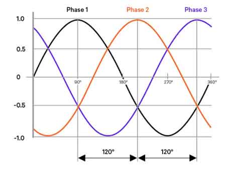
What is three phase electricity? A polyphase AC power system delivering three sinusoidal waveforms 120° apart, enabling balanced loads, efficient power distribution, higher power density, smoother torque in industrial motors, and reliable transmission via transformers.
What Is Three Phase Electricity?
What is Three Phase Electricity? It is a method of delivering electrical power using three alternating currents that are each offset by 120 degrees. In a 3-phase power system, each current reaches its peak at different times within a cycle, ensuring that the power supply remains continuous and stable. This configuration allows for a more efficient and constant flow of…
View more
Delta Wye Transformer Behavior in Real Distribution Systems
A delta wye transformer converts three phase power from a delta primary to a wye secondary to produce a grounded neutral for systems such as 208Y/120V. The connection introduces a 30 degree phase shift and helps contain triplen harmonics while stabilizing line to neutral voltages.
A delta wye transformer is chosen less for theory than for practicality. It creates a usable four-wire secondary with a stable neutral while keeping upstream systems insulated from downstream imbalance, harmonics, and grounding behavior. What matters is not that it steps down the voltage, but that it defines a boundary where real-world loads begin to…
View more
What Is The Function Of Torus Isolation Transformer
What Is the Function of Torus Isolation Transformer? It delivers galvanic isolation, power conditioning, EMI/RFI noise filtering, surge protection, and ground-loop breakup for cleaner audio, safer equipment, and stable home theater and pro AV systems.
What Is the Function of Torus Isolation Transformer?
A torus isolation transformer is a crucial component in electrical systems, providing safety and efficiency by isolating different sections of a circuit. Its unique design, characterized by a toroidal (doughnut-shaped) core, enables it to handle high power loads while minimizing energy loss. By offering galvanic isolation, this transformer protects sensitive equipment from electrical surges and noise,…
View more