Three Phase Electricity Explained


Three Phase Electricity

Three phase electricity delivers power using three alternating currents that are offset in phase. It provides consistent and efficient energy for industrial, commercial, and high-load applications, improving stability and reducing conductor size.


What is Three Phase Electricity?

Three phase electricity is a power system that uses three alternating currents, each offset by 120 degrees, to deliver constant power flow.

✅ Delivers more efficient and stable power than single-phase systems

✅ Ideal for large motors, commercial buildings, and industrial equipment

✅ Reduces conductor material and energy loss over long distances


Three phase voltage, frequency and number of wires

Three phase electricity is the dominant method of electrical power generation, transmission, and distribution across the industrialized world. Unlike single-phase systems, which rely on a single alternating current, three-phase systems use three separate currents, each 120 degrees out of phase with the others. This setup provides a consistent and balanced power flow, making it significantly more efficient for high-demand applications, such as motors, transformers, and large-scale infrastructure. Understanding the difference between alternating current and direct current is essential to grasp how three-phase systems deliver constant power using offset waveforms.


Understanding the Concept

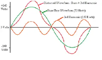
At the heart of a three-phase system are three sinusoidal waveforms, evenly spaced to maintain a continuous flow of energy. When one phase reaches its peak, the others are in different parts of their cycle, ensuring that at any given moment, some power is being delivered. This creates what is known as constant power transfer, a major advantage over single-phase systems that experience power dips between cycles. Since three-phase systems rely heavily on accurate current flow measurement, it’s important to know what ammeters measure and how they help monitor system balance.

For industrial and commercial operations, this stability translates to increased energy efficiency, extended equipment lifespan, and reduced operating costs. Large electric motors, for example, run more smoothly on three-phase power, which avoids the surging and vibration commonly associated with single-phase inputs.


A Brief History

Three phase electricity wasn’t invented by a single person but emerged through the contributions of several pioneers in the late 19th century. Galileo Ferraris in Italy, Nikola Tesla in the United States, and Mikhail Dolivo-Dobrovolsky in Europe all played crucial roles in developing and refining the idea of three-phase alternating current. Tesla’s patents and Dolivo-Dobrovolsky’s practical systems laid the groundwork for what is now a global standard. Engineers use wattmeters to accurately measure real power in three-phase systems, while Watts Law helps calculate the relationships between voltage, current, and power.


Wye and Delta Configurations

Three-phase systems are typically wired in one of two configurations: the Wye (Y) or Delta (Δ) configuration. Each has specific advantages depending on the application:

  • In a Wye connection, each phase is tied to a central neutral point, allowing for multiple voltage levels within the same system. This is common in both commercial and residential applications, where both high and low voltages are required.

  • A Delta connection utilizes a closed loop with no neutral, a configuration commonly found in industrial setups. It delivers the same voltage between all phases and is ideal for running large motors without needing a neutral return path.

One of the most important relationships in these configurations is the √3 ratio between line voltage and phase voltage, a fundamental aspect that engineers use in calculating load, cable sizing, and protective device coordination.


Technical Benefits

Three-phase systems have built-in advantages that go beyond stability. Because the sum of the three phase currents is zero in a balanced load, a neutral wire is often unnecessary. This reduces the amount of conductor material needed, lowering costs and simplifying design. Additionally, three-phase motors naturally create a rotating magnetic field, eliminating the need for external circuitry to start or maintain rotation.

Another major benefit is that power output remains consistent. In single-phase systems, power drops to zero twice per cycle, but three-phase systems deliver non-pulsating power, which is especially important in sensitive or precision equipment. The function of a busbar is especially important in three-phase distribution panels, helping to manage multiple circuit connections efficiently.


Where and Why It’s Used

While most homes use single-phase electricity, three-phase is the standard in virtually all commercial and industrial environments. Factories, data centers, hospitals, and office buildings rely on it to power everything from HVAC systems and elevators to conveyor belts and industrial machines.

Three-phase is also common in electric vehicle (EV) charging stations and renewable energy systems, where efficient, high-capacity delivery is essential. If you're working with three-phase motors or transformers, knowing the role of a conductor and how electrical resistance affects current flow is fundamental to efficient design.

For sites that only have access to single-phase power, phase converters—whether rotary or digital—can simulate three-phase conditions, enabling them to operate three-phase equipment. This flexibility has made three-phase solutions accessible even in remote or rural areas. Three-phase systems often operate at medium voltage, especially in commercial settings, and their stability can reduce the risks of ground faults.


Voltage Levels and Color Codes

Depending on the region, the standard line and phase voltages vary. In North America, typical voltage values include 120/208 volts and 277/480 volts, whereas in Europe and much of Asia, 230/400 volts is more common. Wiring color codes also differ: red/yellow/blue in Europe, black/red/blue in North America, and other variations depending on the country's electrical code. These standards ensure safety, compatibility, and ease of troubleshooting.


The Global Standard for Power

Three-phase electricity is not just a technical solution; it is the foundation of modern electrical infrastructure. Its ability to deliver large amounts of power efficiently, safely, and reliably has made it the system of choice for more than a century. From powering the machines that build our world to the systems that keep us connected, three-phase electricity remains indispensable.


Related Articles


Related News

Understanding Current

Current is the flow of electric charge in circuits, defined by amperage, driven by voltage, limited by resistance, described by Ohm’s law, and fundamental to AC/DC power systems, loads, conductors, and electronic components.


What Is Current?

Current is charge flow in a circuit, measured in amperes and governed by voltage and resistance.

✅ Measured in amperes; sensed with ammeters and shunts

✅ Defined by Ohm’s law: I = V/R in linear resistive circuits

✅ AC alternates; DC is steady; sets power transfer P = V*I


Current is best described as a flow of charge or that the charge is moving. Electrons in motion make up an electric current. This electric current is usually referred to as “current” or “current flow,” no matter how many electrons are moving. Current is a measurement of a rate at which a charge flows through some region of space or a conductor. The moving charges are the free electrons found in conductors, such as copper, silver, aluminum, and gold. The term “free electron” describes a condition in some atoms where the outer electrons are loosely bound to their parent atom. These loosely bound electrons can be easily motivated to move in a given direction when an external source, such as a battery, is applied to the circuit. These electrons are attracted to the positive terminal of the battery, while the negative terminal is the source of the electrons. The greater amount of charge moving through the conductor in a given amount of time translates into a current. For a concise overview of how moving charges create practical circuits, see this guide to current electricity for additional context.


The System International unit for current is the Ampere (A), where


That is, 1 ampere (A) of current is equivalent to 1 coulomb (C) of charge passing through a conductor in 1 second(s). One coulomb of charge equals 6.28 billion billion electrons. The symbol used to indicate current in formulas or on schematics is the capital letter “I.” To explore the formal definition, standards, and measurement practices, consult this explanation of the ampere for deeper detail.

When current flow is one direction, it is called direct current (DC). Later in the text, we will discuss the form of current that periodically oscillates back and forth within the circuit. The present discussion will only be concerned with the use of direct current. If you are working with batteries or electronic devices, you will encounter direct current (DC) in most basic circuits.

The velocity of the charge is actually an average velocity and is called drift velocity. To understand the idea of drift velocity, think of a conductor in which the charge carriers are free electrons. These electrons are always in a state of random motion similar to that of gas molecules. When a voltage is applied across the conductor, an electromotive force creates an electric field within the conductor and a current is established. The electrons do not move in a straight direction but undergo repeated collisions with other nearby atoms. These collisions usually knock other free electrons from their atoms, and these electrons move on toward the positive end of the conductor with an average velocity called the drift velocity, which is relatively a slow speed. To understand the nearly instantaneous speed of the effect of the current, it is helpful to visualize a long tube filled with steel balls as shown in Figure 10-37. It can be seen that a ball introduced in one end of the tube, which represents the conductor, will immediately cause a ball to be emitted at the opposite end of the tube. Thus, electric current can be viewed as instantaneous, even though it is the result of a relatively slow drift of electrons. For foundational concepts that connect drift velocity with circuit behavior, review this basic electricity primer to reinforce the fundamentals.

Current is also a physical quantity that can be measured and expressed numerically in amperes. Electric current can be compared to the flow of water in a pipe. It is measureda at the rate in which a charge flows past a certain point on a circuit. Current in a circuit can be measured if the quantity of charge "Q" passing through a cross section of a wire in a time "t" (time) can be measured. The current is simply the ratio of the quantity of charge and time. Understanding current and charge flow also clarifies how circuits deliver electrical energy to perform useful work.


Electrical current is essentially an electric charge in motion. It can take either the form of a sudden discharge of static electricity, such as a lightning bolt or a spark between your finger and a ground light switch plate. More commonly, though, when we speak of current, we mean the more controlled form of electricity from generators, batteries, solar cells or fuel cells.  A helpful overview of static, current, and related phenomena is available in this summary of electricity types for quick reference.

We can think of the flow of electrons in a wire as the flow of water in a pipe, except in this case, the pipe of water is always full. If the valve on the pipe is opened at one end to let water into the pipe, one doesn't have to wait for that water to make its way all the way to the other end of the pipe. We get water out the other end almost instantaneously because the incoming water pushes the water that's already in the pipe toward the end. This is what happens in the case of electrical current in a wire. The conduction electrons are already present in the wire; we just need to start pushing electrons in one end, and they start flowing at the other end instantly. In household power systems, that push on conduction electrons alternates in direction as alternating current (AC) drives the flow with a time-varying voltage.


Current Formula

Current is rate of flow of negatively-charged particles, called electrons, through a predetermined cross-sectional area in a conductor.

 Essentially, flow of electrons in an electric circuit leads to the establishment of current.

q = relatively charged electrons (C)

t = Time

Amp = C/sec

Often measured in milliamps, mA


Related Articles

View more

Prospective Fault Current Meaning Explained

Prospective fault current (PFC) is the highest electric current that can flow in a system during a short circuit. It helps determine equipment ratings, breaker capacity, and safety measures in electrical installations to prevent overheating, fire, or component failure.


What is the Meaning of Prospective Fault Current?

Prospective fault current refers to the maximum current expected during a short circuit at any point in an electrical system.

✅ Helps size circuit breakers and fuses for safe disconnection

✅ Ensures compliance with installation and safety codes

✅ Prevents equipment damage from excessive short-circuit current

Prospective fault current (PFC) is a key factor in the safety and design of electrical systems. It represents the maximum current that could flow in the event of a fault, such as a short circuit. Understanding PFC is essential for selecting protective devices that can handle fault conditions safely. This article explores what PFC is, how it is measured, and its importance for electrical installations, while addressing key questions. Understanding electrical short circuits is key to calculating prospective fault current and ensuring system safety.

When measuring prospective short circuit current in an electrical system, it’s essential to perform tests between L1 N CPC and L2 N CPC to assess the fault current across different phases and protective conductors. These measurements help identify the maximum prospective fault current present in the system, especially at points involving live conductors. Whether taking note of a single-phase supply or between line conductors on a three-phase supply, proper testing protocols must be followed. Technicians should always use insulated test leads rated for the expected voltage and current levels, and please refer to the test meter manufacturer’s instruction for safe and accurate operation. Reliable results ensure that the protective devices can safely interrupt fault conditions, preventing system damage and ensuring compliance with fault current protection standards.


Frequently Asked Questions

Why is it Important?

Prospective fault current refers to the maximum current that could pass through a system during a fault. The PFC helps determine the breaking capacity of fuses and circuit breakers, ensuring these protective devices can handle high currents safely. This is vital for protecting the electrical installation and those working near it.

Understanding PFC is critical for ensuring increased safety for employees and third parties. Protective devices must be selected to handle PFC; otherwise, they may fail to operate correctly, leading to severe consequences, such as fires or injuries. To fully grasp how PFC affects energy flow, it’s useful to review the concept of electrical resistance in a circuit.


How is Prospective Fault Current Measured or Calculated?

PFC can be measured or calculated using tools such as a multifunction tester, often during fault current testing. The instrument uses a single-phase supply or between line conductors on a three-phase supply to measure the maximum potential current at various points in the installation. Testing often involves checking currents between L1 N CPC, L2 N CPC, and L3 N CPC, which measure current between the lines to neutral in a three-phase system.

When performing these tests, technicians should follow regulation 612.11 of a single-phase supply or between line conductors on a three-phase supply, ensuring that simple and circuit protective conductors are all connected correctly. Accurate testing must also account for maximum current flow. Live testing requires extreme caution, and it is important to refer to the test meter manufacturer’s instructions to ensure proper usage and safety. In three-phase systems, 3-phase electricity significantly impacts how fault current behaves during a short circuit.


What is the difference between PFC and Short-Circuit Current?

Though often confused, prospective fault current and short-circuit current are distinct. Prospective fault current is the theoretical maximum current that could flow in a fault, used to predict the worst-case scenario for selecting protective devices. Short-circuit current refers to the actual current that flows during a fault, which depends on real-time conditions such as circuit impedance. Prospective fault current is one of the many concepts that form the foundation of electricity fundamentals.


How Does Prospective Fault Current Impact the Selection of Protective Devices?

The calculation of PFC plays a critical role in selecting the correct protective devices. Circuit breakers and fuses must have a breaking capacity that matches or exceeds the prospective fault current in the system. If the PFC exceeds the breaking capacity, the protective device may fail, leading to dangerous electrical hazards.

For instance, fault current testing using a multifunction tester between phases and neutral (L1, L2, L3) ensures that protective devices are rated to handle the highest potential fault current in the system. Proper circuit protection ensures that the system can interrupt faults safely, minimizing the risks to workers and equipment.


What Standards and Regulations Govern Prospective Fault Current Calculations?

Various standards, such as IEC 60909, govern how PFC is calculated and how protective devices are selected. These regulations ensure that electrical systems are designed to handle maximum fault conditions safely. Regulation 612.11 further specifies how live testing should be conducted using proper equipment and safety protocols.

It is essential to test PFC at relevant points in the system and follow testing standards to ensure compliance and safety. Devices selected based on PFC calculations help ensure that electrical systems can withstand faults and maintain reliable operation.

Prospective fault current is a crucial element in the safety and reliability of electrical installations. By calculating PFC, engineers can select protective devices that ensure safe operation in the event of a fault. Testing for fault currents at different points in the system and adhering to regulations are essential steps in preventing hazardous conditions.

By choosing protective devices with the appropriate breaking capacity and following safe testing practices, electrical installations can handle fault conditions and protect both workers and equipment from harm. Selecting protective devices that match the PFC is essential for reliable electric power systems design.


Related Articles


View more

Electromagnetic Induction

Electromagnetic induction is the process of generating electric current by changing a magnetic field, forming the basis for transformers, generators, and electric motors in power generation and energy conversion systems.


What is Electromagnetic Induction?

Electromagnetic induction is a fascinating and vital concept shaping how we generate, transfer, and utilize electricity.

✅ Process where a changing magnetic field induces an electric current in a conductor

✅ Fundamental principle behind transformers, generators, and electric motors

✅ Essential for modern power generation, transmission, and energy conversion


Its underlying principles, Faraday's Law and Lenz's Law, explain the phenomena occurring when magnetic fields interact with conductors. At the same time, its various applications, such as electric generators, transformers, induction heating, and wireless charging, have revolutionized our daily lives. As we continue to explore and understand this intricacy, we can look forward to even more innovations and advancements in electricity and magnetism. Understanding Faraday's Law is essential to grasp how changing magnetic fields generate electricity through electromagnetic induction.


Fundamental Laws of Electromagnetic Induction

Faraday's Law of electromagnetic induction, invented by Michael Faraday, is a key principle that states that the induced EMF in a coil is proportional to the rate of change of the magnetic flux (dφ/dt) passing through the coil. The more rapidly the magnetic field changes, the higher the amount of voltage induced will be. This relationship between electricity and magnetism laid the foundation for the development of various electrical devices and systems. The relationship between electricity and magnetism forms the foundation of generators, transformers, and other key electrical systems.

Lenz's Law, another crucial principle, explains the direction of the induced current. It states that the induced current will always flow in a direction that opposes the change in magnetic flux, acting as a stabilizing electromotive force. By combining Faraday's and Lenz's Law, we can better understand how it operates in real-world applications. For a deeper understanding of how voltage is produced in coils, explore the principles of Lenz's Law.


Core Applications: Generators and Transformers

One notable application is the electrical generator, which converts mechanical energy into electrical energy. In a typical generator, a coil of wire rotates within a magnetic field, creating a changing magnetic flux. This change induces a voltage and current in the coil, generating electricity. Generators are commonly used in power plants, automobiles, and other devices requiring a continuous electrical supply. A three-phase transformer uses electromagnetic induction to efficiently transfer power between circuits at different voltages.

Another critical application is the transformer, which transfers electrical energy between circuits with different voltages. Transformers consist of two induction coils wrapped around a shared magnetic core. When an alternating current flows through the primary coil, it creates a magnetic field that induces a voltage in the secondary coil. By adjusting the number of turns in the coils, transformers can step up or down the voltage as needed for specific electrical systems.


Special Phenomena: Eddy Currents, Mutual Inductance, and Self-Inductance

Eddy currents are an intriguing aspect of electromagnetic induction. These currents form when a magnetic field changes, causing swirling, closed loops of electric current within a conductor. Eddy currents generate heat and can lead to energy losses in electrical systems, but they also have practical applications, such as in metal detectors and induction heating. Devices that use electromagnetic induction, such as electric motors, rely on core principles of inductance to regulate energy transfer.

Two critical aspects of electromagnetic induction are mutual inductance and self-inductance. Mutual inductance occurs when the current in one coil induces a voltage in a nearby coil due to their shared magnetic field. Self-inductance refers to a coil's ability to induce a voltage within itself when the current flowing through it changes. Understanding these concepts is crucial for designing and analyzing complex electrical circuits and systems.


Demonstrating the Principle: Coil and Magnet Interaction

In many cases, it involves the interaction of a coil and a magnet, either a permanent magnet or an electromagnet. A bar magnet, for example, may be moved near a coil, or the coil may be moved about the magnet. This motion changes the magnetic field and induces a voltage in the coil, demonstrating the dynamic relationship between electricity and magnetism. Learning the basics of electrical resistance helps explain how eddy currents generate heat in conductive materials.


Modern Impact and Emerging Technologies

It has an immense impact on modern life, from generating electricity in power plants to operating devices like transformers, electric motors, and wireless chargers. The principles of Faraday's Law and Lenz's Law help explain the complex phenomena that occur when magnetic fields interact with conductors. By harnessing these principles, scientists and engineers have created various practical applications that have revolutionized our daily lives.

Electromagnetic induction demonstrates the fundamental relationship between electricity and magnetism and is integral to many aspects of our modern world. Faraday's Law and Lenz's Law underpin this phenomenon, governing the induced voltage and current when magnetic fields change. The applications of electromagnetic induction range from electric generators and transformers to the study of eddy currents, mutual in influence and self-inductance. By understanding these principles, we can continue to innovate and develop new technologies to improve our daily lives and advance our understanding of the world.


Induction Heating

Electromagnetic induction heating is another practical application that relies on electromagnetic induction. This technology utilizes eddy currents to heat conductive materials, such as metals. By placing a conductive material within a rapidly changing magnetic field, eddy currents are generated within the material, producing heat due to their resistance. This heating method has been employed in various industrial processes, including metal hardening, welding, and cooking.

Wireless charging is an emerging technology that utilizes electromagnetic induction to transfer energy between two coils. When an electric current flows through the primary coil, it generates a magnetic field, which induces a voltage in the secondary coil, providing power to the device. This technology has seen increasing adoption in recent years, particularly for charging electric vehicles and smartphones, offering convenience and reduced dependence on cords and cables.


Related Articles


View more

Voltage Drop Formula

The voltage drop formula is V = I × R, where V represents the voltage drop, I represents the current in amperes, and R represents the resistance in ohms. It calculates the amount of voltage lost through a conductor and is essential for designing safe and efficient electrical systems.


What is Voltage Drop Formula?

A voltage drop formula can help you manually calculate the voltage drop in cables under full load in branch circuits. It does not matter if you are working with copper or aluminum conductors. To accurately calculate the voltage drop for a given cable size, length, and current, you need to know the resistance of the type of cable you’re using. 

✅ V = I × R for DC circuits

✅ Accounts for impedance in AC circuits

✅ Helps ensure safe, efficient electrical design

Use our voltage drop calculator to quickly determine wire size, conductor efficiency, and line loss for safer, more reliable electrical installations.


Power Quality Analysis Training

Power Factor Training

Request a Free Power Quality Training Quotation

To determine voltage drop in an electrical system, engineers and electricians use a standard formula that accounts for conductor resistance, current, and circuit length. The National Electrical Code (NEC) provides guidelines for the maximum voltage drop allowed in various installations to ensure efficiency and safety. For both single-phase and three-phase circuits, excessive voltage drop can lead to poor equipment performance and energy loss. To simplify calculations, a voltage drop calculator can quickly assess whether a circuit meets NEC recommendations and optimize conductor sizing accordingly. You can learn more about how electrical resistance affects circuits in our detailed voltage drop guide, which explains causes, calculations, and solutions for safe, efficient power distribution.


DC / single phase calculation

The voltage drop V in volts (V) is equal to the wire current I in amps (A) times 2 times one way wire size length L in feet (ft) times the wire resistance per 1000 feet R in ohms (Ω/kft) divided by 1000:


Vdrop (V) = Iwire (A) × Rwire(Ω)

Iwire (A) × (2 × L(ft) × Rwire(Ω/kft) / 1000(ft/kft))


The voltage drop V in volts (V) is equal to the wire current I in amps (A) times 2 times one way wire length L in meters (m) times the wire resistance per 1000 meters R in ohms (Ω/km) divided by 1000:


Vdrop (V) = Iwire (A) × Rwire(Ω)

Iwire (A) × (2 × L(m) × Rwire (Ω/km) / 1000(m/km))


3 phase calculation

The line-to-line voltage drop V in volts (V) is equal to the square root of 3 times the wire current I in amps (A) times one-way wire length L in feet (ft) times the wire resistance per 1000 feet R in ohms (Ω/kft) divided by 1000:


Vdrop (V) = √3 × Iwire (A) × Rwire (Ω)

= 1.732 × Iwire (A) × (L(ft) × Rwire (Ω/kft) / 1000(ft/kft))


The line-to-line voltage drop V in volts (V) is equal to the square root of 3 times the wire current I in amps (A) times one-way wire length L in meters (m) times the wire resistance per 1000 meters R in ohms (Ω/km) divided by 1000:


Vdrop (V) = √3 × Iwire (A) × Rwire (Ω)

= 1.732 × Iwire (A) × (L(m) × Rwire (Ω/km) / 1000(m/km))


Wire diameter calculations

The n gauge wire diameter, dn in inches (in), is equal to 0.005in times 92 raised to the power of 36 minus gauge number n, divided by 39:


dn (in) = 0.005 in × 92(36-n)/39


The n gauge wire diameter dn in millimetres (mm) is equal to 0.127mm times 92 raised to the power of 36 minus gauge number n, divided by 39:


dn (mm) = 0.127 mm × 92(36-n)/39


Wire cross-sectional area calculations

The n gauge wire's cross-sectional area An in kilo-circular mils (kcmil) is equal to 1000 times the square wire diameter d in inches (in):


An (kcmil) = 1000×dn2 = 0.025 in2 × 92(36-n)/19.5


The n gauge wire's cross-sectional area An in square inches (in2), is equal to pi divided by 4 times the square wire diameter d in inches (in):


An (in2) = (π/4)×dn2 = 0.000019635 in2 × 92(36-n)/19.5


The n gauge wire's cross-sectional area, An, in square millimetres (mm2), is equal to pi divided by 4 times the square wire diameter d in millimetres (mm):


An (mm2) = (π/4)×dn2 = 0.012668 mm2 × 92(36-n)/19.5


Wire resistance calculations

The n gauge wire resistance R in ohms per kilofeet (Ω/kft) is equal to 0.3048×1000000000 times the wire's resistivity ρ in ohm-meters (Ω·m) divided by 25.42 times the cross-sectional area An in square inches (in2):


R(Ω/kft) = 0.3048 × 10⁹ × ρ(Ω·m) / (25.42 × An (in2))


The n gauge wire resistance R in ohms per kilometre (Ω/km) is equal to 1000000000 times the wire's resistivity ρ in ohm-meters (Ω·m) divided by the cross-sectional area An in square millimetres (mm2):


R(Ω/km) = 109 × ρ(Ω·m) / An (mm2)


Related Pages


View more

Electricity Generation Power Production

Electricity generation is the process of producing electric power from various energy sources, including fossil fuels, solar, wind, hydro, and nuclear. It uses turbines and generators to convert mechanical or thermal energy into electrical energy for residential, commercial, and industrial use.


What is Electricity Generation?

Electricity generation is a process that involves producing electrical power from various sources.

✅ Converts mechanical, thermal, or chemical energy into electrical power

✅ Uses generators powered by steam, wind, water, or combustion

✅ Essential for powering homes, industries, and transportation


In the United States, power production from utility-scale generators was about 4.1 trillion kilowatt-hours (kWh) in 2019. Fossil fuels, including coal, natural gas, and petroleum, produced about 63% of the electricity, while nuclear energy produced around 20%. The remaining 17% was generated from renewable energy sources, including solar photovoltaics, wind turbines, and hydroelectric power production. To explore the full process from fuel to flow, see our detailed guide on how electricity is generated.


Electricity Generation Sources Compared

Energy Source How It Generates Electricity Global Usage (approx.) Carbon Emissions Renewable?
Coal Burns to heat water → steam → turbine spins generator 35% High No
Natural Gas Combusts to drive turbines directly or via steam 23% Moderate No
Nuclear Nuclear fission heats water → steam → turbine 10% Low No (but low-carbon)
Hydropower Flowing water spins turbines 15% Very Low Yes
Wind Wind turns large blades connected to a generator 7% Zero Yes
Solar PV Converts sunlight directly into electricity via photovoltaic cells 5% Zero Yes
Geothermal Uses Earth’s internal heat to create steam and turn turbines <1% Very Low Yes
Biomass Burns organic material to generate heat for steam turbines ~1.5% Moderate (depends on fuel) Partially


Hydroelectric Power Generation

Hydroelectric power production units utilize flowing water to spin a turbine connected to a generator. Falling water systems accumulate water in reservoirs created by dams, which then release it through conduits to apply pressure against the turbine blades, driving the generator. In a run-of-the-river system, the force of the river current applies pressure to the turbine blades to produce power. In 2000, hydroelectric generation accounted for the fourth-largest share (7 percent) of electricity production, at 273 billion kWh. Explore how water and electricity interact in hydroelectric plants, where falling water is converted into renewable energy.


Non-Hydro Renewable Energy Sources in Electricity Generation

Non-water renewable sources, including geothermal, refuse, waste heat, waste steam, solar thermal power plants, wind, and wood, contribute only small amounts (about 2 percent) to total power production. In 2019, power production from these sources totalled 84 billion kWh. The entire electric power industry production in 2019 was 3,800 billion kWh, with utilities' net production accounting for 3,015 billion kWh and net generation by non-utility power producers 785 billion kWh.


U.S. Electricity Generation by Energy Source: Trends and Shifts

The United States' share of electrical energy production from different sources has changed more rapidly since 2007 than ever since 1950. On the other hand, Canada's energy production is significantly less than that of the USA, primarily in Ontario and British Columbia. At least three trends are catalyzing these changes: (1) the low price of natural gas; (2) the rise in renewable and distributed generation due to falling costs; and (3) recent Federal and State policies impacting production. There are many innovative ways to generate electricity, from traditional fossil fuels to cutting-edge renewable technologies.


Fuel Source Diversity in U.S. and Canadian Electricity Production

Diversity is a key attribute in U.S. and Canadian electricity production. However, rather than being the result of a deliberative, long-term national initiative, this diversity has developed through spurts of growth in specific production technologies at different times. This is often due to policies, historical events, capital costs, fuel costs, and technological advancements.


Historical Growth of Electricity Generation by Energy Source

Most energy sources have experienced eras of significant capacity growth in terms of terawatt hours: hydro (1930‒1950, not shown); coal (1950-1985); nuclear (1960‒1980); natural gas (1990‒2010); and renewables (2005‒present). Nuclear energy is increasingly recognized as a key solution for achieving carbon reduction goals—learn how it contributes to net-zero emissions.


Changing U.S. Power Generation Mix: Centralized to Distributed Energy

The U.S. generation mix has undergone significant changes over the past few decades and is projected to continue evolving substantially. The U.S. generation fleet is transitioning from one dominated by centralized generators with high inertia and dispatchability to one more hybridized, relying on a mixture of traditional, centralized production and variable utility-scale and distributed renewable energy production.


Power Generation Technologies: From Diesel Engines to Wind Turbines

To generate power, various sources are utilized, including diesel engines, gas turbines, and nuclear power plants. Fossil fuels, including natural gas and coal, are burned to create hot gases that go through turbines, which spin the copper armature inside the generator and generate an electric current. In a nuclear power plant, nuclear reactions generate heat that is used to heat water, which then turns into steam and passes through a turbine to produce electricity. In a wind turbine, the wind pushes against the turbine blades, causing the rotor to spin and generating an electric current. In a hydroelectric turbine, flowing or falling water pushes against the turbine blades, causing the rotor to spin and generating an electric current. As the global energy landscape evolves, many experts are re-evaluating the role of nuclear power—learn more in our feature on the future of nuclear energy.


Electricity Generation by Utilities and Non-Utility Power Producers

To meet these immediate demands, utilities and nonutility power producers operate several electric generating units powered by various fuel sources. Renewable fuels, such as water, geothermal, wind, and other renewable energy sources like solar photovoltaics, are used as sources of power, alongside fossil fuels and uranium.


motor


diagram


Fossil Fuel Electricity Generation: Coal, Natural Gas, and Petroleum

Coal was the fuel used to generate the largest share (51.8 percent) of electricity in 2000, with natural gas and petroleum accounting for 16.1 percent and 3 percent, respectively. Steam-electric generating units burn fossil fuels, such as coal, natural gas, and petroleum, to produce steam. This steam is then used to turn a turbine into a generator, producing power. On the other hand, gas turbine generators burn fuels to create hot gases, which also go through a turbine, spinning the copper armature inside the generator and generating an electric current. Diesel engine generators are also used, where the combustion occurs inside the engine's cylinders, which are connected to the generator's shaft. The mechanical energy provided by the turbine drives the generator, which in turn produces energy.


Electricity Generation Trends and the Global Shift Toward Renewables

The production of electrical energy has experienced various eras of significant capacity growth in the United States, Canada, and other countries worldwide. The future of power production is transitioning to a more hybridized generation fleet that relies on a combination of traditional, centralized power production and variable utility-scale and distributed renewable energy sources. Low natural gas prices drive this transition, the rise of renewable and distributed energy sources, and recent Federal and State policies that impact generation. Discover the most common renewable energy sources powering the shift toward a cleaner, more sustainable electricity future.


Enhance your expertise in clean energy with our comprehensive Renewable Energy Grid Integration Training course. Designed for electrical professionals, this course covers the challenges and solutions associated with connecting solar, wind, and other renewable energy sources to the power grid. Stay ahead of industry trends, improve system reliability, and gain valuable skills to support the transition to a sustainable energy future. Enroll today and take the next step in your professional development.


Frequently Asked Questions

How is electricity generated from renewable energy sources?

Electricity is generated from renewable energy sources by converting the energy of the sun, wind, water, or earth into electrical energy. For example, solar photovoltaic panels generate power directly from sunlight, wind turbines to generate electricity from wind energy, and hydroelectric power plants generate power from falling water.


What are the different types of fossil fuels used?

The different types of fossil fuels used include coal, natural gas, and petroleum. Coal is the most commonly used fossil fuel for energy production, followed by natural gas and oil.


What are the advantages and disadvantages of using nuclear power plants for electricity generation?

Advantages of using nuclear power plants include that they produce a large amount of energy with a low amount of fuel, emit less carbon dioxide than fossil fuel power plants, and are not dependent on weather conditions like wind or solar power. Disadvantages include the risks associated with nuclear accidents, the high cost of building and maintaining nuclear power plants, and the long-term storage of nuclear waste.


How do gas turbines work to generate electricity?

Gas turbines burn natural gas or other fuels to heat air, which expands and drives the turbine. Finally, the turbine is connected to a generator that converts the mechanical energy of the turbine into electrical energy.


What is the role of steam turbines in electricity generation?

Steam turbines are commonly used to convert thermal energy from steam into mechanical energy that drives a generator. Steam is produced by burning fossil fuels or using heat from nuclear reactions or geothermal sources. The steam drives the turbine blades, which are connected to the generator to produce electricity.


What are some examples of non-renewable energy sources?

Examples of non-renewable energy sources used for power production include fossil fuels, such as coal, natural gas, and petroleum, as well as nuclear energy.


How is electricity generated and distributed in the United States?

Various power plants, including those powered by fossil fuels, nuclear energy, and renewable energy sources, generate electricity in the United States. Electric power is transported over a complex network of power lines and transformers to homes, businesses, and other consumers through local utility companies. The Federal Energy Regulatory Commission (FERC) and various state regulatory agencies regulate power distribution.


Related Articles


View more

Wireless Electricity

Wireless electricity transmits power without wires using electromagnetic fields, such as magnetic resonance or microwave transmission. It enables charging devices remotely, powering sensors, and improving efficiency in smart grids, EVs, and wireless charging systems.


What is Wireless Electricity?

Wireless electricity refers to the transmission of electrical energy without physical conductors like wires.

✅ Powers devices through electromagnetic fields, like inductive coupling

✅ Enables contactless charging in consumer electronics and EVs

✅ Supports smart grids, IoT, and remote sensors with flexible energy delivery

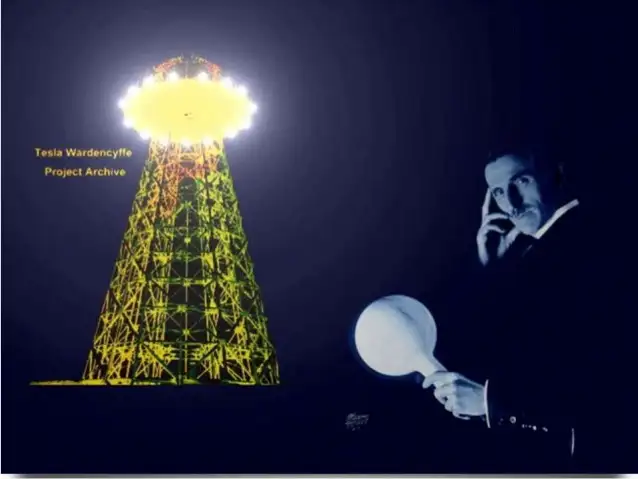
Wireless electricity, also known as wireless power transmission, was first conceptualized by Nikola Tesla, a pioneer in the field of alternating current (AC) electricity. Tesla’s groundbreaking experiments at Colorado Springs in 1899 showcased how power could be transmitted without wires using a magnetic field. He used a Tesla coil to transmit 100 million volts of high power over a distance of 26 miles, wirelessly powering 200 light bulbs and an electric motor. His vision was to develop a wireless system capable of transmitting power over long distances with minimal energy loss.

Tesla’s system relied on a high-frequency alternating current and magnetic resonance to transmit power wirelessly. His experiments with the Tesla coil laid the groundwork for modern wireless technologies, including short-range wi

reless power transmission systems, such as wireless charging pads and Wi-Fi routers. Wireless charging pads today utilize magnetic fields to transmit power to devices, a concept similar to Tesla’s idea of harnessing the Earth’s resonance to transmit power over longer distances. Tesla’s vision extended beyond short-range wireless systems—he dreamed of a global system where energy flows freely through the air without requiring a direct line of sight.

Tesla’s experiments also demonstrated the efficiency of wireless systems. The Tesla coil could transmit power wirelessly to fluorescent light bulbs even when they were several feet away from the coil. This concept of powering devices wirelessly has evolved over time, with companies like Wi-Charge developing systems to transmit power wirelessly to small devices. In Tesla’s time, he envisioned a world where any amount of power could be transmitted wirelessly across the globe. However, financial struggles eventually led to the abandonment of his wireless power transmission projects, including the unfinished Wardenclyffe tower on Long Island. Devices powered wirelessly still rely on efficient energy flow, making concepts such as electrical resistance and impedance crucial to design and performance.

Despite Tesla’s challenges, modern advancements have kept his vision alive. Short-range wireless power transmission systems, like those used in Wi-Fi routers and wireless charging pads, are now commonplace. These technologies utilize magnetic fields to transmit power wirelessly over short distances, offering a practical solution for wirelessly charging devices such as smartphones and laptops. Wi-Charge is exploring the potential of wirelessly charging devices without requiring close contact, enabling more flexible and efficient energy distribution. Tesla’s coil and modern systems like Wi-Charge operate based on resonant principles, closely related to inductance and capacitance.


Modern Innovations in Wireless Electricity

Recent breakthroughs have brought Tesla’s dream closer to reality:

  • In 2024, DARPA successfully transmitted 800 watts of power over 5 miles using a laser beam—enough to make popcorn at the receiver site.

  • KAIST in South Korea demonstrated the ability to charge 40 smartphones at once using magnetic resonance over a distance of 5 meters.

  • Detroit’s Corktown district now hosts a functioning inductive charging roadway, allowing EVs to charge wirelessly while in motion.

These examples show that wireless electricity is no longer a distant vision but a rapidly advancing technology with real-world applications. Concepts such as watts, volts, and amperes remain fundamental even in advanced wireless systems.


Types of Wireless Power Transmission Technologies

Technology Type Description and Use Cases
Inductive Coupling Short-range charging pads for phones, laptops, and wearables
Magnetic Resonance Mid-range charging for larger devices and multiple receivers simultaneously
Microwave Transmission Long-range point-to-point energy transfer; used in research and satellites
Laser Power Beaming High-efficiency focused beams for distant targets; demonstrated by DARPA
Infrared Light (Wi-Charge) Contactless charging for smart locks and IoT devices


Applications of Wireless Electricity

  • Consumer Electronics: Wireless charging pads and smart home devices are now common.

  • Electric Vehicles (EVs): Inductive charging roads and parking pads reduce dependency on cable stations.

  • Medical Implants: Enables powering of implants and biosensors without invasive wiring.

  • Remote Sensors: In agriculture, factories, and infrastructure, wireless power extends sensor life.

  • Smart Grids: Flexible energy distribution for remote locations and emergency response.


Challenges and Future Outlook

Despite its promise, wireless electricity faces challenges:

  • Efficiency drops over distance

  • Alignment issues in inductive systems

  • Line-of-sight limitations in laser and IR systems

  • Safety regulations for high-power beaming

However, the future is promising. Emerging materials, such as metamaterials and metasurfaces, are enhancing transmission efficiency. AI-enhanced beam control, dynamic alignment systems, and frequency-agnostic receivers are under development.

From Tesla's early experiments to DARPA's record-setting laser transmission, wireless electricity is evolving into a transformative force. As the technology matures, its applications will expand, powering a world that may one day be truly wire-free.


Related Articles


View more

Sign Up for Electricity Forum’s Newsletter

Stay informed with our FREE Newsletter — get the latest news, breakthrough technologies, and expert insights, delivered straight to your inbox.

Electricity Today T&D Magazine Subscribe for FREE

Stay informed with the latest T&D policies and technologies.
  • Timely insights from industry experts
  • Practical solutions T&D engineers
  • Free access to every issue

Download the 2025 Electrical Training Catalog

Explore 50+ live, expert-led electrical training courses –

  • Interactive
  • Flexible
  • CEU-cerified