What is Ohm's Law?


what is ohm's law

Ohm’s Law defines the essential link between voltage, current, and resistance in electrical circuits. It provides the foundation for circuit design, accurate troubleshooting, and safe operation in both AC and DC systems, making it a core principle of electrical engineering.


What is Ohm’s Law?

Ohm’s Law is a fundamental principle of electrical engineering and physics, describing how voltage, current, and resistance interact in any circuit.

✅ Defines the relationship between voltage, current, and resistance

✅ Provides formulas for design, safety, and troubleshooting

✅ Essential for understanding both AC and DC circuits

When asking what is Ohm’s Law, it is useful to compare it with other fundamental rules like Kirchhoff’s Law and Ampere’s Law, which expand circuit analysis beyond a single equation.


What is Ohm's Law as a Fundamental Principle

Ohm's Law is a fundamental principle in electrical engineering and physics, describing the relationship between voltage, current, and resistance in electrical circuits. Engineers can design safe and efficient electrical circuits by understanding this principle, while technicians can troubleshoot and repair faulty circuits. The applications are numerous, from designing and selecting circuit components to troubleshooting and identifying defective components. Understanding Ohm's Law is essential for anyone working with electrical circuits and systems.


Who was Georg Ohm?

Georg Simon Ohm, born in 1789 in Erlangen, Germany, was a physicist and mathematician who sought to explain the nature of electricity. In 1827, he published The Galvanic Circuit Investigated Mathematically, a groundbreaking work that defined the proportional relationship between voltage, current, and resistance. Though his research was initially dismissed, it later became recognized as one of the cornerstones of modern electrical science.

His work introduced key concepts such as electrical resistance and conductors, and his law became fundamental to circuit design and analysis. The scientific community honored his contribution by naming the unit of resistance — the ohm (Ω) — after him. Today, every student and professional who studies electricity carries his legacy forward.

Georg Simon Ohm


What is Ohm’s Law Formula

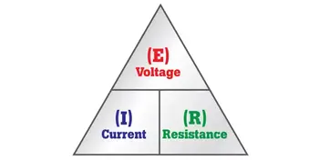
At the heart of the law is a simple but powerful equation:

V = I × R

  • V is voltage, measured in volts (V)

  • I is current, measured in amperes (A)

  • R is resistance, measured in ohms (Ω)

Rearranging the formula gives I = V/R and R = V/I, making it possible to solve for any unknown value when the other two are known. This flexibility allows engineers to calculate required resistor values, predict circuit performance, and confirm safe operating conditions.

In both DC and AC systems, the law provides the same basic relationship. In AC, where current and voltage vary with time, resistance is replaced with impedance, but the proportional link remains the same.

The Ohm’s Law equation explains how the amount of electric current flowing through a circuit depends on the applied voltage and resistance. Current is directly proportional to voltage and inversely proportional to resistance, illustrating how electrical charge flows under various conditions. To maintain consistency in calculations, the law employs standard units: volts (V) for voltage, amperes (A) for current, and ohms (Ω) for resistance. Since Ohm’s Law formula defines the relationship between these values, it directly connects to related concepts such as electrical resistance and voltage.


Understanding the Formula

The strength of Ohm’s Law lies in its versatility. With just two known values, the third can be calculated, turning raw measurements into useful information. For an engineer, this might mean calculating the resistor needed to protect a sensitive device. For a technician, it may indicate whether a failing motor is caused by excess resistance or a low supply voltage.


How the Formula Works in Practice

Consider a simple example: a 12-volt battery connected to a 6-ohm resistor. Using the law, the current is I = V/R = 12 ÷ 6 = 2 amperes. If resistance doubles, the current halves. If the voltage increases, the current rises proportionally.

In practical terms, Ohm’s Law is used to:

  • calculate resistor values in electronic circuits,

  • verify safe current levels in wiring and equipment,

  • determine whether industrial loads are drawing excessive power,

  • troubleshoot faults by comparing measured and expected values.

Each of these tasks depends on the same simple equation first described nearly two centuries ago. Applying Ohm’s Law often involves calculating current in DC circuits and comparing it with alternating current systems, where impedance replaces simple resistance.


Modern Applications of Ohm’s Law

Far from being outdated, Ohm’s Law remains central to modern technology. In electronics, it ensures safe current levels in devices from smartphones to medical equipment. In renewable energy, it governs the design and balance of solar panels and wind turbines. In automotive and electric vehicle systems, battery management and charging depend on accurate application of the law. Even in telecommunications, it ensures signals travel efficiently across cables and transmission lines. In power engineering, Ohm’s Law works alongside Watts Law and power factor to determine efficiency, energy use, and safe operating conditions.

These examples demonstrate that the law is not a relic of early science but an active tool guiding the design and operation of contemporary systems.


Resistance, Conductivity, and Real-World Limits

Resistance is a material’s opposition to current flow, while conductivity — its inverse — describes how freely charge moves. Conductors, such as copper and aluminum, are prized for their high conductivity, while insulators, like rubber and glass, prevent unwanted current flow.

In reality, resistance can change with temperature, pressure, and frequency, making some devices nonlinear. Semiconductors, diodes, and transistors do not always follow Ohm’s Law precisely. In AC systems, resistance expands to impedance, which also considers inductance and capacitance. Despite these complexities, the proportional relationship between voltage and current remains an essential approximation for analysis and design. Exploring basic electricity and related principles of electricity and magnetism shows why Ohm’s Law remains a cornerstone of both theoretical study and practical engineering.


Frequently Asked Questions


What is an example of Ohm's Law?

A simple example in action is a circuit consisting of a battery, a resistor, and a light bulb. If the voltage supplied by the battery increases, the current flowing through the circuit will also increase, causing the light bulb to glow brighter. Conversely, if the resistance of the circuit is increased by adding another resistor, the current flowing through the circuit will decrease, causing the light bulb to dim.


What are the three formulas in Ohm's Law?

The three formulas are I = V/R, V = IR, and R = V/I. These formulas can solve a wide range of problems involving electrical circuits.


Does Ohm’s Law apply to all electrical devices?

Not always. Devices such as diodes and transistors are nonlinear, meaning their resistance changes with operating conditions. In these cases, Ohm’s Law provides only an approximation.

When asking What is Ohm’s Law, it becomes clear that it is far more than a formula. It is the framework that makes electricity predictable and manageable. By linking voltage, current, and resistance, it offers a universal foundation for design, troubleshooting, and innovation. From the earliest experiments to today’s electronics and power grids, Georg Ohm’s insight remains as relevant as ever.

Related News

What is an Arc Fault?

An arc fault is a dangerous electrical discharge between conductors or to ground. It generates intense heat and light, often caused by damaged insulation, frayed wires, or loose connections, posing major electrical safety and fire hazards.


What is an Arc Fault?

An arc fault is an unintended electrical discharge that occurs when insulation or wiring fails, producing dangerous heat that can ignite fires and damage circuits.

✅ Caused by frayed wires or loose connections

✅ Produces intense heat and light energy

✅ Prevented by Arc Fault Circuit Interrupters (AFCIs)


Basic Protection Relay Training

Short Circuit Study Training

Request a Free Training Quotation


Understanding Arc Faults and Electrical Safety

An arc fault is a hazardous electrical event that can lead to severe consequences, including fires and substantial property damage. Understanding how faults occur, how to prevent them, and why protective measures like Arc Fault Circuit Interrupters (AFCIs) are essential can significantly improve home and workplace safety.

When electrical current jumps across a gap or an unintended path, it forms an electric arc. This arc generates extremely high temperatures—often exceeding 10,000°F—capable of igniting nearby insulation, wood framing, or other combustible materials. Faults are typically caused by damaged, frayed, or aging wiring, loose terminal connections, or punctured cables from nails and screws during construction. For more insight into advanced safety devices, learn how an arc fault interrupter breaker detects hazardous arcing and disconnects power before a fire can start.

Arc fault protection is especially important in areas where people live and spend time, such as family rooms, dining rooms, and living rooms, where electrical wiring runs behind walls containing materials such as wood framing or insulation that can easily ignite. Modern safety standards, as mandated by the National Electrical Code, require the installation of Arc Fault Circuit Interrupters (AFCIs) in these spaces to prevent fires caused by faults. When combined with Ground Fault Circuit Interrupters, which protect against electrical shock, AFCIs provide comprehensive protection against both fire and shock hazards in residential and commercial environments.


Types of Arc Faults

Arc faults can appear in different forms, each with its own risks and detection requirements:

  • Series Faults – Occur along a single conductor, usually from a broken wire or loose terminal. These arcs produce less current but can still ignite fires.

  • Parallel Faults – Form between two conductors (hot-to-neutral or hot-to-ground). These faults create higher current levels and more intense arcing.

  • Ground Faults – Happen when current leaks or shorts to a grounded surface, such as a metal outlet box or appliance casing. Explore how ground fault protection complements AFCIs by guarding against current leakage that could cause electric shock or parallel arc conditions.

Recognizing these types helps electricians and inspectors identify the right protection strategies and select appropriate AFCI devices. To see how fault current behavior impacts fault risks, review our explanation of available fault current and why accurate short-circuit studies are essential for system safety.


How AFCI Detection Works

AFCIs are intelligent safety devices designed to detect the unique electrical signatures of faults. They continuously monitor current waveforms and frequencies, distinguishing dangerous arcs from normal switching arcs (such as those produced by light switches or vacuum cleaners).

When an AFCI identifies an abnormal frequency pattern consistent with arcing, it trips the circuit within milliseconds—disconnecting power before the fault can ignite a fire. This advanced “signature detection” technology is required by modern safety codes and has saved countless lives and properties. For more insight into advanced safety devices, learn how an arc fault interrupter breaker detects hazardous arcing and disconnects power before a fire can start.


Limitations and Nuisance Tripping

While AFCIs are highly effective, they can occasionally cause nuisance tripping. This occurs when the device misinterprets harmless electrical noise as a fault, typically triggered by motors, dimmers, or other electronic devices. Regular inspection, proper grounding, and updated AFCI models help minimize these false positives. If nuisance tripping persists, it’s advisable to have an electrician verify circuit wiring and device compatibility. To understand how electrical systems respond to fault conditions, refer to our detailed explanation of protective relay coordination, which ensures that circuit breakers isolate faults without disrupting unaffected circuits.


Code Requirements and Standards

Arc fault protection is mandated by both U.S. and Canadian electrical codes:

  • National Electrical Code (NEC 210.12) requires AFCI protection for all 120-volt, single-phase, 15- and 20-amp branch circuits supplying living areas such as bedrooms, family rooms, dining rooms, and similar spaces.

  • Canadian Electrical Code (CEC Section 26) similarly mandates AFCI in dwelling units.

  • IEEE 1584 provides calculation guidelines for flash hazards in industrial power systems, complementing residential and commercial fault safety standards.

Following these standards ensures compliance and dramatically reduces fire risks across residential, commercial, and industrial applications.


Statistics and Case Studies

According to the U.S. Consumer Product Safety Commission (CPSC), electrical fires cause over 51,000 residential fires annually, resulting in more than 500 deaths and $1.3 billion in property damage. Studies show that AFCI protection can prevent more than half of these incidents, highlighting its critical role in modern electrical safety systems.


Emerging Technologies in Arc Fault Detection

New generations of AFCIs utilize microprocessors and artificial intelligence to enhance accuracy and minimize false trips. These smart devices analyze waveform patterns with greater precision, detecting high-impedance arcs and subtle irregularities. Future technologies may integrate predictive analytics and IoT monitoring to diagnose potential faults before they become hazards. Finally, explore comprehensive methods of electrical surge protection, which safeguard sensitive equipment from voltage spikes often linked to lightning events.


Common Causes of Arc Faults

  • Damaged or aging electrical wiring

  • Loose terminal connections in outlets or switches

  • Overloaded circuits or faulty appliances

  • Nails or screws penetrating electrical cables

  • Deteriorated insulation from heat, moisture, or rodents

Regular maintenance and periodic inspections by a licensed electrician are essential preventive measures.


Arc Fault vs Ground Fault vs Short Circuit

Fault Type Description Main Hazard Protection Device
Arc Fault Unintended arcing between conductors or within wiring Fire risk AFCI
Ground Fault Current flowing to ground unintentionally Electric shock GFCI
Short Circuit Direct contact between conductors High current / equipment damage Circuit Breaker

Understanding these differences helps ensure that electrical protection systems are properly matched to the specific hazards they are intended to address.


Frequently Asked Questions


Why does my AFCI keep tripping?

Often due to electronic interference, shared neutrals, or actual wiring issues. Replace outdated AFCIs and consult a professional if tripping persists.


Can I retrofit AFCIs into older panels?

Yes. AFCI breakers can replace standard breakers in most modern panels. Have a qualified electrician confirm compatibility before installation.


Are AFCIs required everywhere?

While required in most living spaces, some regions exempt areas like garages or unfinished basements. Check the NEC or CEC requirements for your jurisdiction.


Related Articles


View more

What is Low Voltage?

Low voltage refers to electrical systems operating at 50 to 1000 volts AC or 120 to 1500 volts DC. Common in residential, commercial, and control circuits, it reduces shock risks while powering lighting, HVAC, security systems, and automation equipment safely.


What is Low Voltage?

Low voltage is a range of electrical power levels below high-voltage thresholds.

✅ Reduces risk of electrical shock in residential and commercial settings

✅ Powers lighting, security, HVAC, and control systems

✅ Common in telecommunications and automation applications


In today's technologically driven world, understanding the concept of low voltage (LV) is essential. Low voltage systems are widely used across industries, homes, and offices, making them an integral part of our daily lives. This article provides an overview of LV, its applications, safety measures, and regulations, incorporating the keywords provided. Low voltage systems are designed to operate below 600 volts, unlike high voltage systems that present increased shock hazards.

The low voltage definition is relatively simple: Any electrical system or equipment operating at a voltage level less than or equal to 600 volts. LV systems in the United States are generally categorized as those working between 50 and 600 volts. These systems are utilized in various applications due to their low power consumption and reduced risk of electric shock. Understanding the concept of voltage is essential when working with residential or industrial low voltage wiring.


Applications

Low voltage applications are diverse and include control rooms, distribution systems, lighting, communication systems, and security systems. LV wiring is often used in these applications, as it is designed for smaller currents and offers increased safety compared to regular wiring. This wiring type is also more cost-effective and easier to install. Voltage drop can significantly impact the performance of low voltage circuits, especially over long wiring runs.

Regarding LV safety, it is crucial to take necessary precautions as even LV electrical equipment can pose risks. For example, to minimize the chance of electric shock, one should always turn off the power supply before working on any electrical equipment and use insulated tools. Additionally, it is essential to adhere to local LV regulations and standards to ensure a safe working environment.


Devices

Low voltage devices are found in various settings, from residential to commercial and industrial. Some examples of low voltage devices include thermostats, doorbells, intercom systems, and landscape lighting. These devices usually require transformers to convert the higher voltage from the main power supply to a lower voltage suitable for operation.

Regulations and standards for LV installations vary by country and region. However, the National Electrical Code (NEC) provides guidelines and requirements for LV installations to ensure safety and reliability in the United States. Professionals working with low voltage systems must adhere to these guidelines and any additional local regulations.

Low voltage transformers and power supplies are critical in distributing low voltage electricity. Transformers are used to step down higher voltages from the main power supply to the required LV level. In contrast, power supplies regulate and distribute electrical energy to various devices. Low voltage distribution systems are designed to efficiently deliver electricity to low voltage equipment while maintaining safety and reliability.


Systems

While low voltage systems are generally safer than high voltage electrical systems, they still require proper handling and adherence to safety measures. High-voltage transmission systems are used to transport electricity over long distances from power plants to substations. High voltages range from 100 kV to 765 kV, while ultra-high voltages can reach above 800 kV. Large industrial facilities, such as factories that use medium-voltage systems, typically operate between 1 kV and 35 kV.

Understanding LV is crucial today, as these systems are widely used in various applications. With proper installation, adherence to regulations, and safety precautions, LV systems can provide numerous devices with an efficient and reliable power supply. As a result, low voltage systems play an essential role in our daily lives, whether for lighting, communication, or security. Key electrical components such as resistors and capacitors are frequently used in low voltage control systems.


Frequently Asked Questions


Is "low voltage" defined differently in 110V systems and 220V systems?

While the term "low voltage" describes electrical systems operating at a voltage level lower than a certain threshold, the specific voltage ranges considered low voltage can vary slightly between countries and regions due to differences in their electrical distribution systems. However, the general concept remains the same across 110V systems in North America and 220V systems in the EU. For efficient power distribution, low voltage systems rely on solid grounding practices, making ground faults and electrical faults important safety considerations.

In North America, low voltage typically refers to electrical systems operating between 50 and 600 volts. In contrast, in the EU, the term "LV" is defined by the Low Voltage Directive (LVD), which covers electrical equipment designed for use with a voltage rating of 50 to 1000 volts for alternating current (AC) and 75 to 1500 volts for direct current (DC).

Despite these minor differences in the defined voltage ranges, the reasons behind the classification of LV systems remain consistent. LV systems are generally considered safer than their high voltage counterparts, as the risk of electric shock is lower. Additionally, they consume less power, making them more energy-efficient and cost-effective for certain applications.

The main factor causing the difference in voltage levels between regions is the choice of electrical distribution systems. For example, 110-120V systems are more common in North America, while in Europe and many other parts of the world, 220-240V systems are standard. This difference is primarily due to historical reasons and the evolution of each region's electrical infrastructure over time.

Regardless of these regional differences in voltage levels, the fundamental principles and safety considerations for LV systems remain largely the same. Both 110V and 220V systems use LV electrical equipment and wiring to provide power for various applications while adhering to regional safety standards and regulations to ensure these systems' safe and efficient operation. The behavior of current in low voltage applications is best understood by applying Ohm’s Law, which explains the relationship between voltage, current, and resistance.


What are examples of low voltage systems?

Low voltage systems are widely used in various residential, commercial, and industrial applications due to their increased safety and energy efficiency. Here are some examples of LV systems:

Lighting systems: Low voltage lighting, such as LED lights and halogen lamps, is commonly used for residential and commercial purposes, including landscape lighting, recessed lighting, and track lighting. These systems often use transformers to step down the voltage from the main power supply to a suitable level for the lights.

Security systems: LV is used in security systems, including alarm systems, access control systems, and surveillance cameras. These systems require a stable and reliable power source with minimal risk of electrical hazards.

Communication systems: LV wiring is utilized in various communication systems, including intercoms, telephone lines, and data networks. It enables the reliable transmission of data and voice signals while minimizing energy consumption and interference.

Audio and video systems: LV components are used in home theatre systems, speakers, and AV equipment. The low voltage wiring ensures minimal signal loss and interference for better audio and video quality.

HVAC controls: Thermostats, sensors, and control panels for heating, ventilation, and air conditioning systems often use low voltage wiring and components to maintain efficient energy use and reliable control of the HVAC system.

Doorbells and chimes: LV systems are commonly used in doorbells and chime systems to ensure safe and reliable operation.

Fire alarm systems utilize LV wiring and components to provide a reliable means of detecting and responding to potential fire hazards while minimizing the risk of electrical hazards.

Home automation systems often utilize LV for controlling and automating various devices, including lighting, appliances, and security systems. This allows for the energy-efficient and safe operation of connected devices.

Solar power systems: In small-scale solar power installations, LV DC systems are used to store and distribute the electricity generated by solar panels. These systems typically include charge controllers, batteries, and inverters to efficiently manage the power supply.

Industrial control systems: LV is used in various industrial applications to control and monitor machinery and equipment. This includes programmable logic controllers (PLCs), motor controls, and sensor networks, which require stable and reliable power sources with minimal risk of electrical hazards. Devices like multimeters and voltmeters are essential tools for testing and maintaining low voltage installations.


Related Articles


View more

What is Voltage?

Voltage is the electrical potential difference between two points, providing the force that moves current through conductors. It expresses energy per charge, powering devices, controlling circuits, and ensuring efficient and safe operation of electrical and electronic systems.


What is Voltage?

Voltage is the electric potential difference, the work done per unit charge (Joules per Coulomb). It: 

✅ Is the difference in electric potential energy between two points in a circuit.

✅ Represents the force that pushes electric current through conductors.

✅ It is measured in volts (V), and it is essential for power distribution and electrical safety.

To comprehend the concept of what is voltage, it is essential to understand its fundamental principles. Analogies make this invisible force easier to picture. One of the most common is the water pressure analogy: just as higher water pressure pushes water through pipes more forcefully, higher voltage pushes electric charges through a circuit. A strong grasp of voltage begins with the fundamentals of electricity fundamentals, which explain how current, resistance, and power interact in circuits.

Another way to imagine what is voltage is as a hill of potential energy. A ball placed at the top of a hill naturally rolls downward under gravity. The steeper the hill, the more energy is available to move the ball. Likewise, a higher voltage means more energy is available per charge to move electrons in a circuit.

A third analogy is the pump in a water system. A pump creates pressure, forcing water to move through pipes. Similarly, a battery or generator functions as an electrical pump, supplying the energy that drives electrons through conductors. Without this push, charges would remain in place and no current would flow.

Together, these analogies—water pressure, potential energy hill, and pump—show how voltage acts as the essential driving force, the “electrical pressure” that enables circuits to function and devices to operate. Since voltage and Current are inseparable, Ohm’s Law shows how resistance influences the flow of electricity in every system.

These analogies help us visualize voltage as pressure or stored energy, but in physics, voltage has a precise definition. It is the work done per unit charge to move an electric charge from one point to another. Mathematically, this is expressed as:

V = W / q

where V is voltage (in volts), W is the work or energy (in joules), and q is the charge (in coulombs). This equation shows that one volt equals one joule of energy per coulomb of charge.

In circuit analysis, voltage is also described through Ohm’s Law, which relates it to current and resistance:

V = I × R

where I is current (in amperes) and R is resistance (in ohms). This simple but powerful formula explains how voltage, current, and resistance interact in every electrical system.

Italian physicist Alessandro Volta played a crucial role in discovering and understanding V. The unit of voltage, the volt (V), is named in his honor. V is measured in volts, and the process of measuring V typically involves a device called a voltmeter. In an electrical circuit, the V difference between two points determines the energy required to move a charge, specifically one coulomb of charge, between those points. The history of voltage is closely tied to the History of Electricity, where discoveries by pioneers like Volta and Franklin have shaped modern science.

An electric potential difference between two points produces an electric field, represented by electric lines of flux (Fig. 1). There is always a pole that is relatively positive, with fewer electrons, and one that is relatively negative, with more electrons. The positive pole does not necessarily have a deficiency of electrons compared with neutral objects, and the negative pole might not have a surplus of electrons compared with neutral objects. But there's always a difference in charge between the two poles. So the negative pole always has more electrons than the positive pole.


Fig 1. Electric lines of flux always exist near poles of electric charge.


The abbreviation for voltage measurement is V. Sometimes, smaller units are used. For example, the millivolt (mV) is equal to a thousandth (0.001) of a volt. The microvolt (uV) is equal to a millionth (0.000001) of a volt. And it is sometimes necessary to use units much larger than one volt. For example, one kilovolt (kV) is equal to one thousand volts (1,000). One megavolt (MV) is equal to one million volts (1,000,000) or one thousand kilovolts. When comparing supply types, the distinction between Direct Current and AC vs DC shows why standardized voltage systems are essential worldwide.

The concept of what is voltage is closely related to electromotive force (EMF), which is the energy source that drives electrons to flow through a circuit. A chemical battery is a common example of a voltage source that generates EMF. The negatively charged electrons in the battery are compelled to move toward the positive terminal, creating an electric current.

In power distribution, three-phase electricity and 3 Phase Power demonstrate how higher voltages improve efficiency and reliability.

Voltage is a fundamental concept in electrical and electronic systems, as it influences the behavior of circuits and devices. One of the most important relationships involving V is Ohm's Law, which describes the connection between voltage, current, and resistance in an electrical circuit. For example, Ohm's Law states that the V across a resistor is equal to the product of the current flowing through it and the resistance of the resistor. 

The voltage dropped across components in a circuit is critical when designing or analyzing electrical systems. Voltage drop occurs when the circuit components, such as resistors, capacitors, and inductors, partially consume the V source's energy. This phenomenon is a crucial aspect of circuit analysis, as it helps determine a system's power distribution and efficiency. Potential energy is defined as the work required to move a unit of charge from different points in an electric dc circuit in a static electric field.  Engineers often analyze Voltage Drop to evaluate circuit performance, alongside concepts like Electrical Resistance.

Voltage levels are standardized in both household and industrial applications to ensure the safe and efficient operation of electrical equipment. In residential settings, common voltage levels range from 110 to 240 volts, depending on the country. Industrial applications often utilize higher voltages, ranging from several kilovolts to tens of kilovolts, to transmit electrical energy over long distances with minimal losses.

Another important distinction in the realm of voltage is the difference between alternating current (AC) and direct current (DC). AC alternates periodically, whereas DC maintains a constant direction. AC is the standard for most household and industrial applications, as it can be easily transformed to different voltage levels and is more efficient for long-distance transmission. DC voltage, on the other hand, is often used in batteries and electronic devices.

Voltage is the driving force behind the flow of charge carriers in electrical circuits. It is essential for understanding the behavior of circuits and the relationship between voltage, current, and resistance, as described by Ohm's Law. The importance of V levels in household and industrial applications, as well as the significance of voltage drop in circuit analysis, cannot be overstated. Finally, the distinction between AC and DC voltage is critical for the safe and efficient operation of electrical systems in various contexts.

By incorporating these concepts into our understanding of voltage, we gain valuable insight into the world of electricity and electronics. From the pioneering work of Alessandro Volta to the modern applications of voltage in our daily lives, it is clear that voltage will continue to play a crucial role in the development and advancement of technology. Foundational principles such as Amperes Law and the Biot Savart Law complement voltage by describing how currents and magnetic fields interact.


Related Articles


View more

How to Save Electricity?

How to save electricity? Improve energy efficiency, switch to LED lighting, manage standby power, use smart thermostats, insulate homes, schedule heavy appliances off-peak, and conduct energy audits to cut power consumption and lower bills.


How to Save Electricity?

Reduce power consumption with LEDs, smart thermostats, insulation, and off-peak usage to lower energy bills.

✅ Upgrade to LED lighting and ENERGY STAR appliances

✅ Program smart thermostats; set HVAC to efficient ranges

✅ Eliminate standby power with advanced power strips


How to Save Electricity is a popular question. It involves energy conservation and lessens real dollars and preserves a public resource. Here are some ways to cut energy costs without compromising your lifestyle too much. For a deeper primer on cutting household consumption, explore this saving electricity guide for actionable steps.


Control heating and cooling costs

In some climates, heating and cooling represent the largest part of household energy use. In many climates, running your air conditioner at 78 instead of 72 will earn 40% of your cooling bill. You don't have to freeze or roast to death in order to use less energy and earn money. In some climates, heating and cooling represent the largest part of household energy use. In many climates, running your air conditioner at 78 instead of 72 will earn 40% of your cooling bill. You don't have to freeze or roast to death in order to use less energy and earn money.In some climates, heating and cooling represent the largest part of household energy use. In many climates, running your air conditioner at 78 instead of 72 will earn 40% of your cooling bill. You don't have to freeze or roast to death in order to use less energy and earn money. Here are a few tips:

Understanding how HVAC loads draw electric power can help you schedule operation during cooler periods for efficiency.

  • How to Save Electricity? Make sure your filters are clean. Check with the manufacturer of your equipment or with your utility company to see if filters on your units need to be cleaned.
  • Don't heat or cool when no one is home. If you are going to be gone for more than a half an hour, you can turn your heating or cooling off or down. Don't turn off the heat in a cold climate because that may result in the pipes breaking.
  • Supplement your main unit with portable units Running a fan can help you use less air conditioning. Using portable heaters when you are asleep or otherwise staying in one room can mean less use of heat if it means that you don't have to use the main unit.
  • Try setting your thermostat to run less frequently Turn your air conditioner up a degree or two or your heater down a degree or two and see if you still can be comfortable.
  • Time your opening and closing of windows and drapes to reduce heading and cooling costs. On cold, sunny days, opening curtains and drapes while leaving windows closed will help you heat your home. Opening the windows on summer nights helps cool your home. Buying storm windows in some climates reduces heating costs.
  • Check for holes in your roof and in your pipes. This can help reduce up to 10 per cent of your heating and cooling costs.

Track your improvements by reading your electricity meter regularly and noting weekday versus weekend patterns.


Get energy saving ideas from your utility company 

Utility companies are among the few businesses who hope that you use less of their product. Most power companies are anxious to postpone construction of new power plants, so they strongly encourage customers to use less power. 
Utility companies offer energy audits, tips, and other help for customers who want to reduce energy consumption. Call your local utility or log onto their website to see what they have to offer. Many utilities explain how electricity cost components like demand and time-of-use rates affect bills.


Other Electricity Saving tips:

  • Consider how to increase your energy efficiency when buying appliances Appliances are labeled with energy usage comparison tables. Look at these figures. Also, you may be able to buy an adapter to make your older appliances more energy efficient.
  • Turn off appliances that no one is using Turning off TV's, lamps, computers, VCR's, ovens, and other appliances that no one is using can reduce electric energy consumption. Even turning them off for short periods can produce noticeable results.
  • See if an alternative energy company is available In California, electrical deregulation is beginning to result in alternative providers of electric power. This is a trend that should increase nationally. See if that option is available to you.
  • Install low-flow heads in your water closets. Also, check your water heater's temperature and set it for 120 degrees. Putting insulation over your water heater and pipes can also help.
  • Wash and dry only full loads of clothing or dishes

Stay aware of regional electricity prices so you can plan high-use activities for lower-cost periods.

You may not make you rich, but it will help you cut down some on your costs and will help prevent blackouts and power shortages in your community.

Are your company's profits being eroded by escalating energy costs? Can you gamble that your energy costs will go down in the future? What are you doing about preparing and protecting your company from spiraling energy costs?

If you operate in competitive markets, review how electricity deregulation shapes supplier choices and contract terms.

Do you have the knowledge of the dynamic market with the right equipment that will make the 'smart decisions' and make an effective difference in your energy consumption and see your energy bill go down?

Facilities with inductive loads can cut charges by improving power factor through correction equipment and better motor controls.


Do you know about the latest technologies that you can implement now?

These questions can be answered by our new Industrial, Commercial & Institutional Energy Efficiency Handbook. This 100+ page book is jammed with practical information on reducing energy consumption, increase Energy efficiency by using modern technologies such as variable frequency drives, high efficiency electrical devices, energy efficient lighting, energy management control systems, metering and management systems, as well as fan, pump and blower efficiency improvements. We will also list Federal, State, utility and Canadian government programs that will reduce your energy consumption and increase your energy efficiency.


Related Articles

View more

Capacitance in Parallel Explained

Capacitance in parallel occurs when capacitors are connected side by side, and their values add together. This increases total capacitance, ensures stable voltage, supports efficient charge distribution, and is essential in electronics, energy storage, and reliable circuit design.


What is Capacitance in Parallel?

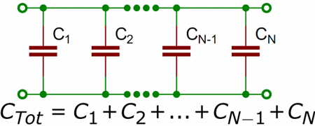
Capacitance in parallel occurs when capacitors are connected across the same two points in a circuit, causing their capacitance to add up:

✅ Increases total capacitance by summing all capacitor values

✅ Improves energy storage and voltage regulation in circuits

✅ Common in AC and DC applications for a consistent charge supply

To learn the fundamentals, see what is capacitance, which explains how capacitors store charge, the role of farads, and why this property is essential in circuits and energy storage.


Understanding Parallel Capacitor Behavior

When capacitors are connected in parallel, the effective plate area increases, and the total capacitance is the sum of the individual capacitances. Figure 1 shows a simplified parallel circuit. The total charging current from the source divides at the junction of the parallel branches. To fully understand how capacitors behave in parallel, it helps to revisit the basics of what is a capacitor and how capacitance works in circuits. 


Fig. 1 - Simplified parallel circuit.


There is a separate charging current through each branch, allowing a different charge to be stored by each capacitor. Using Kirchhoff’s current law, the sum of all the charging currents is then equal to the total current. The sum of the charges (Q) on the capacitors is equal to the total charge on the capacitors. The voltages (E) across all of the parallel branches are equal. With all of this in mind, a general equation for capacitors in parallel can be determined as:

QT = Q1 + Q2 + Q3

Because Q = CE: CTET = C1E1 + C2E2 + C3E3

Voltages can be factored out because:

ET = E1 + E2 + E3

Leaving us with the equation for capacitors in parallel:

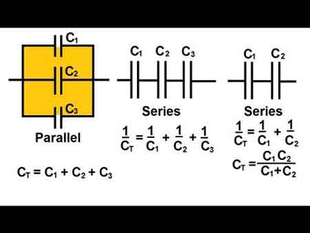
CT = C1 + C2 + C3

Consider the following example:

If C1 = 330μF, C2 = 220μF

Then CT = 330μF + 220μF = 550μF

To calculate the total capacitance in a parallel combination, you simply add the values of the individual capacitors together. This method is straightforward and differs from series connections, where the reciprocal of each capacitor must be used. The total increases with the number of capacitors added in parallel, making this configuration ideal for applications that require higher capacitance. When designing circuits, understanding how a parallel combination enhances energy storage compared to a series connection is crucial for selecting the optimal number of capacitors to achieve the desired performance. For a detailed breakdown of how capacitance is measured, check out the unit of capacitance to understand farads and their practical conversions.

Since voltage remains constant across parallel capacitors, a firm grasp of what is voltage and its behavior in different configurations is essential.


Capacitance in Alternating Current

If a source of alternating current is substituted for the battery, the capacitor acts quite differently than it does with direct current. When an alternating current is applied in the circuit, the charge on the plates constantly changes. [Figure 2] This means that electricity must flow first from Y clockwise around to X, then from X counterclockwise around to Y, then from Y clockwise around to X, and so on. Although no current flows through the insulator between the plates of the capacitor, it constantly flows in the remainder of the circuit between X and Y. In a circuit in which there is only capacitance, current leads the applied voltage, as contrasted with a circuit in which there is inductance, where the current lags the voltage. Capacitors in AC circuits are deeply influenced by alternating current, where the current leads the voltage due to capacitive reactance.


Fig. 2 - Capacitor in an AC circuit.

The parallel connection rule CT = C1 + C2 + C3 reflects the broader principles of resistances in parallel, though capacitance behaves in an additive way instead of being reciprocal.


Capacitive Reactance Xc

The effectiveness of a capacitor in allowing an AC flow to pass depends upon the capacitance of the circuit and the applied frequency. To what degree a capacitor allows an AC flow to pass depends largely upon the capacitive value of the capacitor, given in farads (F). The greater the capacitance, the greater the number of electrons, measured in coulombs, necessary to bring the capacitor to a fully charged state. Once the capacitor approaches or actually reaches a fully charged condition, the polarity of the capacitor will oppose the polarity of the applied voltage, essentially acting then as an open circuit.

To further illustrate this characteristic and how it manifests itself in an AC circuit, consider the following:
If a capacitor has a large capacitive value, a high-frequency current can alternate through it without the capacitor ever reaching a full charge. In this case, the capacitor may offer very little resistance to current.

However, the smaller the capacitance, the fewer electrons are required to bring it up to a full charge, and it is more likely that the capacitor will build up enough of an opposing charge to present significant resistance, possibly behaving like an open circuit. Understanding Kirchhoff’s Law helps explain how current divides among parallel capacitors and supports accurate calculations.


Comparison With Series Capacitance

Understanding the difference between series and parallel capacitance is critical for circuit design:

Configuration Total Capacitance Voltage Behavior Current Behavior
Parallel Adds directly: CT = C1 + C2 + ... Same across all components Divides among branches
Series Inverse sum: 1/CT = 1/C1 + 1/C2 + ... Divides across components Same through all components
  • Parallel is best when you want more capacitance and voltage stability.

  • Series is used when you need a lower total capacitance or to increase voltage tolerance.

To explore how capacitors behave when connected end-to-end, visit capacitance in series, which explains the reciprocal formula and voltage behavior.


Practical Design Considerations

  • Voltage Rating: In parallel, all capacitors share the same voltage. The lowest voltage rating among capacitors determines the safe operating voltage of the group.

  • Physical Size: Adding more capacitors increases board space. Designers must balance performance with space constraints.

  • Energy Storage: Parallel configurations store more energy, making them ideal for power supplies, smoothing circuits, and buffering in audio and RF systems.

Real-world circuit design also requires familiarity with types of capacitors, as their materials and tolerances affect total capacitance and performance.


Real-World Applications of Parallel Capacitors

  • Power Supply Smoothing: Bulk capacitors in parallel stabilize the DC output.

  • Decoupling Noise: Small-value capacitors placed in parallel with larger ones eliminate high-frequency interference.

  • Tuning Circuits: In radio circuits, variable capacitors, when used in parallel with fixed ones, help tune specific frequencies.

For a broader context, you can explore how electrical resistance and reactive power relate to capacitive elements in AC power systems.


Related Articles


View more

What is a Voltage Regulator?

What is a voltage regulator? A control circuit that stabilizes DC output from AC/DC power supplies using feedback, reference, and PWM; includes linear LDOs and switching buck/boost converters, improving line/load regulation, ripple suppression, efficiency.


What Is a Voltage Regulator?

It keeps voltage steady despite load changes, using linear or switching control to cut ripple, protecting circuits.

✅ Maintains setpoint via reference, error amplifier, feedback loop

✅ Linear LDOs offer low noise; dropout defined by headroom

✅ Switching buck/boost provide high efficiency, EMI needs filtering


What is a voltage regulator, and how does it work?

A voltage regulator is a component of the power supply unit that maintains a constant voltage supply through all operational conditions. Voltage regulators can regulate both AC and DC voltages, ensuring a steady, constant voltage supply. The output voltage is usually lower than the input voltage. The regulator compares the output voltage to a reference voltage and uses the difference to adjust the output voltage. An external voltage source or a circuit within the regulator typically sets the reference voltage. The regulator monitors the output voltage and adjusts it to maintain the reference voltage, which ensures a constant output voltage despite fluctuations in the input voltage or load conditions. For a succinct refresher on fundamentals, review what voltage is and how it is quantified in electrical systems.


Why is voltage regulation important in electronic circuits?

Voltage regulation is essential in electronic circuits because all electronic devices are designed to run at predetermined power ratings, including voltage and current. Therefore, the voltage supply should ideally be constant and steady for the device's proper functioning. Any variation in the voltage supply can lead to device malfunction or even failure. Voltage regulation ensures proper device operation and prevents damage due to voltage fluctuations. Design targets often align with a system's nominal voltage to ensure interoperability and safety margins.


What are the different types of voltage regulators?

They can be classified based on their physical design, active components used, and working principle. For example, linear and switching regulators are the most common classifications of active voltage regulators (that use amplifying components like transistors or op-amps).

Linear regulators use amplifying components like transistors or op-amps to regulate the output voltage. They are simple and reliable but less efficient as they waste excess power as heat. Linear regulators are suitable for low-power applications where efficiency is not a major concern. In many loads the effective behavior of a resistor network shapes the current draw and thermal budget.

Switching regulators, on the other hand, use inductors and capacitors to store and transfer energy, making them more efficient than linear regulators. They are commonly used in battery-powered devices as they consume less power. Switching regulators are more complex than linear regulators and require careful design and layout.

They can also be classified based on their physical design. Voltage regulators used in low-voltage electronic devices are usually integrated circuits. Power distribution centers providing AC power to residential and industrial consumers use more sophisticated and mechanically large voltage regulators that maintain a rated voltage regardless of consumption demands across the area. For context, consumer gadgets often operate within defined low-voltage categories that influence package choice and safety standards.


Can a voltage regulator be used for both AC and DC power sources?

Yes, they can be used for both AC and DC power sources. AC voltage regulators are used in power distribution centers to maintain a constant voltage supply to consumers. DC voltage regulators are used in electronic devices that run on DC power sources, such as batteries or DC power supplies. When selecting between sources, it helps to understand the difference between AC and DC and how each impacts regulation strategy.


What is the difference between a voltage regulator and a voltage stabilizer?

Linear voltage regulators and voltage stabilizers are similar in function as they both regulate the output voltage. However, the main difference between the two is in their working principle. They maintain a constant output voltage by adjusting the voltage as needed to maintain a reference voltage. On the other hand, voltage stabilizers maintain a constant output voltage by using a transformer and voltage regulator ics to stabilize the voltage output.


How do you choose the right one for a specific application?

When choosing one for a specific application, several factors should be considered, including the input voltage range, output voltage range, output current requirements, efficiency, and operating temperature range. During prototyping, verify rails with a calibrated voltmeter to confirm stability under representative loads.

The input voltage range refers to the maximum and minimum input voltages that the regulator can handle. The output voltage range is the range of output voltages that the regulator can provide. The output current requirement refers to the amount of current that the regulator needs to supply to the load. Efficiency is an essential factor as it determines how much power is wasted as heat. Higher efficiency regulators consume less power and generate less heat, which is especially important in battery-powered devices. The operating temperature range is also important as some higher output voltage regulators can operate only within a certain temperature range.

It is crucial to select the appropriate type of regulator for the application. For example, linear regulators are suitable for low-power applications where efficiency is not a major concern while switching regulators are more appropriate for high-power applications that require higher efficiency.

There are various types, including adjustable, boost step-up and buck-boost regulators, and constant output. Adjustable ones allow the user to adjust the output voltage as needed, making them versatile for different duty cycle applications. Boost step-up and buck-boost regulators can increase or decrease the output voltage from the input voltage, making them useful for applications where the input voltage is lower than the required output voltage. Constant output voltage regulators maintain a constant output voltage despite changes in input voltage or load conditions.

In electronic circuits, voltage fluctuations and ripple voltage can be problematic. Voltage fluctuations refer to rapid changes in the voltage level, while ripple voltage refers to the residual AC voltage that remains after rectification. Voltage regulators can help minimize voltage fluctuations and ripple voltage in electronic circuits, ensuring proper device operation. After rectification, understanding what a rectifier does helps explain the origin of ripple and filtering needs.


Related Articles

View more

Sign Up for Electricity Forum’s Newsletter

Stay informed with our FREE Newsletter — get the latest news, breakthrough technologies, and expert insights, delivered straight to your inbox.

Electricity Today T&D Magazine Subscribe for FREE

Stay informed with the latest T&D policies and technologies.
  • Timely insights from industry experts
  • Practical solutions T&D engineers
  • Free access to every issue

Download the 2025 Electrical Training Catalog

Explore 50+ live, expert-led electrical training courses –

  • Interactive
  • Flexible
  • CEU-cerified