Lenz's Law Explained


Lenz’s Law is a principle of electromagnetic induction stating that induced current flows in a direction that opposes the change in magnetic flux producing it. This rule ensures energy conservation and explains how circuits, coils, generators, and transformers behave in changing fields.


What is Lenz’s Law?

Lenz’s Law, rooted in Faraday’s Law of Induction, states that the direction of an induced current or electromotive force (emf) always opposes the change in magnetic flux that produced it. This principle safeguards conservation of energy in electromagnetic systems.

✅ Explains opposing force in induced current and magnetic fields

✅ Fundamental to understanding circuits, transformers, and generators

✅ Practical in energy conversion, electric motors, and induction device

Lenz's Law, named after the Russian physicist Heinrich Lenz (1804-1865), is a fundamental principle in electromagnetism. It states that the direction of the induced electromotive force (emf) in a closed conducting loop always opposes the change in magnetic flux that caused it. This means that the induced current creates a magnetic field that opposes the initial change in magnetic flux, following the principles of conservation of energy. A strong grounding in basic electricity concepts makes it easier to see why Lenz’s Law is central to modern circuit design.


Understanding Lenz's Law enables us to appreciate the science behind various everyday applications, including electric generators, motors, inductors, and transformers. By exploring the principles of Lenz's Law, we gain insight into the inner workings of the electromagnetic world that surrounds us. Engineers use this principle when designing three-phase electricity systems and 3-phase power networks to maintain energy balance.

Lenz's Law, named after the Russian physicist Heinrich Lenz (1804-1865), is a fundamental principle that governs electromagnetic induction. It states that the induced electromotive force (emf) in a closed conducting loop always opposes the change in magnetic flux that caused it. In simpler terms, the direction of the induced current creates a magnetic field that opposes the initial change in magnetic flux. 

Lenz's Law is a fundamental law of electromagnetism that states that the direction of an induced electromotive force (EMF) in a circuit is always such that it opposes the change that produced it. Mathematically, Lenz's Law can be expressed as:

EMF = -dΦ/dt

Where EMF is the electromotive force, Φ is the magnetic flux, and dt is the change in time. The negative sign in the equation indicates that the induced EMF is in the opposite direction to the change in flux.

Lenz's Law is closely related to Faraday's Law of electromagnetic induction, which states that a changing magnetic field induces an EMF in a circuit. Faraday's Law can be expressed mathematically as:

EMF = -dΦ/dt

where EMF is the electromotive force, Φ is the magnetic flux, and dt is the change in time.

Ampere's Law and the Biot-Savart Law are also related to Lenz's Law, as they describe the behaviour of electric and magnetic fields in the presence of currents and charges. Ampere's Law states that the magnetic field around a current-carrying wire is proportional to the current and the distance from the wire. The Biot-Savart Law describes the magnetic field produced by a current-carrying wire or a group of wires. Because Lenz’s Law governs the behavior of induced currents, it directly complements Ampere’s Law and the Biot-Savart Law in explaining magnetic fields.

Together, these laws provide a complete description of the behaviour of electric and magnetic fields in various situations. As a result, they are essential for understanding the operation of electric motors, generators, transformers, and other devices.

To better understand Lenz's Law, consider the scenario of a bar magnet moving toward a coil of wire. When the magnet moves closer to the coil, the number of magnetic field lines passing through the coil increases. According to Lenz's Law, the polarity of the induced emf in the coil is such that it opposes the increase in magnetic flux. This opposition creates an induced field that opposes the magnet's motion, ultimately slowing it down. Similarly, when the magnet is moved away from the coil, the induced emf opposes the decrease in magnetic flux, creating an induced field that tries to keep the magnet in place.

The induced field that opposes the change in magnetic flux follows the right-hand rule. If we hold our right hand around the coil such that our fingers point in the direction of the magnetic field lines, our thumb will point in the direction of the induced current. The direction of the induced current is such that it creates a magnetic field that opposes the change in the magnetic flux.

The pole of the magnet also plays a crucial role in Lenz's Law. When the magnet's north pole moves towards the coil, the induced current creates a magnetic field that opposes the north pole's approach. Conversely, when the magnet's south pole moves towards the coil, the induced current creates a magnetic field that opposes the south pole's approach. The direction of the induced current follows the right-hand rule, as we discussed earlier.

It is related to Faraday's Law of Electromagnetic Induction, which explains how a changing magnetic field can induce an electromotive force (emf) in a conductor. Faraday's Law mathematically describes the relationship between the induced electromotive force (emf) and the rate of change of magnetic flux. It follows Faraday's Law, as it governs the direction of the induced emf in response to the changing magnetic flux. To fully understand how electromagnetic induction works, it is helpful to see how Faraday’s discoveries laid the foundation for Lenz’s Law.

It is also related to the phenomenon of eddy currents. Eddy currents are loops of electric current induced within conductors by a changing magnetic field. The circulating flow of these currents generates their magnetic field, which opposes the initial magnetic field that created them. This effect is in line with Lenz's Law and has practical applications, such as in the braking systems of trains and induction cooktops.

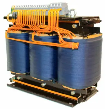
Lenz's Law has numerous practical applications in our daily lives. For example, it plays a significant role in the design and function of electric generators, which convert mechanical energy into electrical energy. In a generator, a rotating coil experiences a changing magnetic field, resulting in the generation of an electromotive force (emf). The direction of this induced emf is determined by Lenz's Law, which ensures that the system conserves energy. Similarly, electric motors operate based on Lenz's Law. In an electric motor, the interaction between the magnetic fields and the induced electromotive force (emf) creates a torque that drives the motor. In transformers, including 3-phase padmounted transformers, Lenz’s Law explains why flux changes are controlled for efficiency and safety.

Lenz's Law is an essential concept in the design of inductors and transformers. Inductors are electronic components that store energy in their magnetic field when a current flows through them. They oppose any change in the current, following the principles of Lenz's Law. Transformers, which are used to transfer electrical energy between circuits, utilize the phenomenon of electromagnetic induction. By understanding it, engineers can design transformers.


Related Articles


Related News

Green Electricity

Green electricity integrates renewable energy sources such as solar PV, wind turbines, and hydropower into smart grids, improving power quality, decarbonization, efficiency, and reliability for industrial loads and utility-scale networks.


What is green electricity?

Green electricity is renewable-source power via smart grids to cut emissions and enhance system efficiency.

✅ Integrates PV, wind, hydro with power electronics and converters

✅ Enhances grid stability via inverters, FACTS, and smart protection

✅ Reduces CO2, improves efficiency, supports microgrids and storage


Green electricity is a term describing what is thought to be environmentally friendly sources of electricity. Typically, this refers to renewable and non-polluting energy power sources. For a broader perspective on how different technologies contribute, see this overview of sources of electricity across modern grids.

Green electricity includes natural energetic processes which can be harnessed with little pollution. Anaerobic digestion, geothermal power, wind power, small-scale hydropower, solar power, biomass power, tidal power and wave power fall under such a category. Some versions may also include power derived from the incineration of waste. Comparisons with other clean options are summarized in this guide to alternative electricity solutions used worldwide.


Energies Wind Electricity 
The winds that blow across the UK can be harnessed by turbines to provide Green electricity. Wind turbines sited in suitable locations already provide a small, but growing percentage of the UK's electricity, and are used successfully all around the world. In fact wind power is the world's fastest growing energy source! Wind turbine technology has greatly improved over the last ten years, making wind turbines quieter and more efficient so that electricity generated from the wind is now often competitive with traditional coal-fired and nuclear power stations. Wind turbines are also beginning to be built at sea — in the future much of our electricity could come from these offshore windfarms. Understanding how turbines integrate into national systems is covered in this primer on electricity generation methods and planning.


Solar Electricity
Many people believe that we don't get much solar Green electricity here in the UK. In fact solar power is already being used to provide essential power for many types of equipment being used in both remote and urban areas across the country. A solar photovoltaic (PV) module works by converting sunlight directly into electricity (even on cloudy days) using semiconductor technology. The vast majority of solar modules available today use "waste" silicon from the computer chip industry as the semiconductor material. They can be integrated into buildings and even made into roof tiles virtually indistinguishable from normal tiles. 
Solar Electricity can also be used to heat water directly using specially designed collectors. Even in winter a useful amount of hot water can be produced from roof top collectors. A third way to use solar energy is simply to design buildings to make maximum use of the sun. Using this so-called 'passive solar' approach, much of the energy that we currently use for heating, lighting and air conditioning can be saved. Homeowners can explore practical steps to generate electricity with rooftop PV and storage.


Hydro Electricity
Water turbines have been used to provide Green electricity for over 100 years and presently provide over 1% of the UK's electricity. Although most of the possible sites for large hydropower stations in the UK have already been developed, there is a large potential for smaller schemes. These can either use a small dam or work as a 'run of the river' system which has a minimal impact on the local environment. Design considerations for small schemes are outlined in this resource on water electricity systems for communities.


Wave Electricity
Many different devices have been designed over the years to try and capture some of this huge energy resource — the latest one has recently started generating Green electricity on the isle of Islay, off the West Coast of Scotland. In this machine waves hitting the shore are channelled into a large tube to power a specially designed turbine. With the proper support, wave power could provide a significant proportion of the UK's electricity needs in the future.


Tidal Electricity
Tidal power has been used in Britain for over a thousand years — at the time of the Doomsday book over 5,000 tide powered mills were recorded. Unlike other Green electricity renewable energy sources, which depend on the weather, tidal power is as predictable as the tides themselves. One way to capture tidal energy is to build a barrage across an estuary, storing water behind it as the tide rises and then releasing the stored water through turbines at low tide. Several sites around the UK could be suitable for this type of tidal system, the largest being the Severn Estuary. Another way is to use 'marine current turbines', which work like underwater wind turbines, harnessing tidal currents instead of the winds.


Geothermal Electricity
Geothermal energy comes from hot rocks deep underground. In some parts of the world steam comes to the surface and can be used to run steam turbines to produce Green electricity directly. In other places water can be pumped down and heated by the rocks to make steam. Geothermal energy can also be used to provide hot water and heating for buildings. Case studies of enhanced systems are available in this overview of geothermal electricity projects worldwide.


Biomass Electricity
Either agricultural wastes or specially grown plants can be used as a fuel to run small Green electricity power stations. As plants grow they absorb carbon dioxide (the main gas responsible for climate change) which is then released when the plants are burnt. So using biomass does not add any extra carbon dioxide into the atmosphere. Specially grown 'energy crops' provide not only an environmentally sound source of electricity, but also an important new opportunity for farmers. Analyses of supply chains and grid impacts appear in this review of electricity production from biomass and other renewables.


Landfill gas Converted to Electricity
As rubbish decomposes in the landfill sites where our household waste is dumped, it gives off methane gas. This gas can be captured and burnt in a gas turbine to produce an attractive Green electricity tariff. Burning the gas does give off carbon dioxide but since methane, which is emitted from the landfill site, is in fact a much more powerful greenhouse gas it is better to burn it than to allow the methane to escape into the atmosphere. There are already many landfill gas systems operating in the UK.


Waste Incineration Electricity
The UK generates an enormous amount of waste, and space at landfill sites is quickly running out. The best solution would be to recycle as much of the waste as possible, but instead incinerators are being constructed to burn the waste. In some cases the energy is being used to generate green electricity. However many environmentalists are still concerned about the emission of harmful dioxins and also about the loss of a valuable resources that could have been recycled. You can read about Greenpeace's views on incineration.


Related Articles

View more

Basic Electricity – Understanding Current, Voltage, Resistance, and Power

Basic electricity refers to the fundamental concepts of electric charge, current, voltage, and resistance. It explains how electric circuits work, how energy flows, and how components like wires, batteries, and switches interact in homes, schools, and industries.


What is Basic Electricity?

Basic electricity refers to the foundational principles that explain how electric energy is generated, transmitted, and used in circuits. When an electric current flows through a conductor, it creates a magnetic field (or “flux”) around it.

✅ Explains current, voltage, resistance, and power in simple terms

✅ Describes how electric circuits operate and transfer energy

✅ Essential for understanding household wiring, batteries, and switches

Understanding the fundamentals of voltage is essential for grasping how electric circuits function — see our full explanation of voltage.

The strength of this magnetic field increases when the conductor is shaped into a coil with multiple turns. In electrical engineering, this coiled conductor is known as an inductor. If a steady direct current (DC) flows through the coil, it forms an electromagnet—an object with magnetic properties that can be switched on and off using a basic electrical switch.


Basic Electrical Theory

There are four basic electrical quantities that we need to know:

  • Current

  • Potential Difference (Voltage)

  • Power

  • Resistance


Electrical Current

Current is the movement of electric charge through a conductor. Each electron carries a charge of 1.6 × 10⁻¹⁹ coulombs—too small to measure individually—so we measure charge in groups called coulombs. When 1 coulomb of charge passes through a point in a circuit per second, the current is  1 ampere (A). Electric current is measured in amperes and is essential to the functioning of all electrical systems. Learn how voltage drop affects electrical performance and safety in residential and industrial systems. You can estimate losses in long-distance wiring with our easy-to-use voltage drop calculator. For step-by-step guidance on circuit loss calculations, explore the voltage drop formula explained clearly.


Potential Difference

Voltage, or potential difference, refers to the energy per unit charge in a circuit. It represents the work each charge can perform. Think of voltage as the electrical pressure that pushes electrons through a conductor. Higher voltage means more potential energy available to do work, such as lighting a bulb or powering a motor.


Power in a Circuit

Electrical power is the rate at which energy is used or transferred in a circuit. It can be calculated using the formula:

Power (W) = Voltage (V) × Current (A)

This equation is fundamental in both residential and industrial applications, from estimating energy usage to designing electrical systems.


Electrical Resistant Behaviour

Resistance is the opposition to the flow of electric current. It determines how much current will flow for a given voltage. Materials like copper have low resistance and conduct electricity well, while materials like rubber have high resistance and are used as insulators. Learn how voltage drop affects electrical performance and safety in residential and industrial systems.


Electromagnetic Induction

There’s a reciprocal relationship between electric current and magnetism. When a magnet is moved past a conductor at a right angle, it induces a voltage in the conductor—a principle known as electromagnetic induction. The polarity of the induced voltage depends on the direction and orientation of the magnetic field.

This effect becomes more noticeable when the conductor is formed into a coil. As the north pole of the magnet passes the coil, voltage is induced, and current flows. When the south pole passes, the induced voltage reverses polarity, and the current changes direction. This principle is the foundation of generator operation. You can estimate losses in long-distance wiring with our easy-to-use voltage drop calculator.


The Generator and the Sine Wave

In an electric generator, coils placed on opposite sides of a rotating magnet generate alternating current (AC). These voltages combine, doubling the output. For example, a 120-volt, 60-Hz generator creates a wave that oscillates from +169.7V to -169.7V.

This wave is called a sine wave because the voltage at any point corresponds to the sine of the magnet’s angle of rotation. The cycle repeats 60 times per second in North America (60 Hz), creating the household AC power we are familiar with. For step-by-step guidance on circuit loss calculations, explore the voltage drop formula explained clearly.


Forms of Electricity: AC and DC

Electricity exists in two major forms:

  • Alternating Current (AC): The direction of current flow alternates regularly. AC electricity is used in power grids because it is easier to transmit over long distances and is compatible with devices such as transformers and capacitors.

  • Direct Current (DC): The current flows steadily in one direction. DC is commonly used inside electronics and battery-powered devices. Unlike AC, the voltage remains constant, making it easy to measure with a DC voltmeter.


AC – Alternating Current

Alternating current is the most common form of electricity used in homes, businesses, and utilities. It alternates direction 50–60 times per second, depending on the region. AC is generated by AC generators and is favored for its ability to change voltage levels easily, making it efficient for transmission over long distances. Sudden dips in power can disrupt equipment — find out what causes voltage sag and how to prevent it.


DC – Direct Current

Direct current flows continuously in one direction. Because its voltage is steady or changes very slowly, it’s easy to measure. It is used in battery-powered systems and internal electronic circuits. Unlike AC, DC cannot be easily stepped up or down in voltage without the use of complex circuitry.

When calculating AC power, engineers use RMS (Root Mean Square) voltage, which gives an effective value comparable to DC. For example, 120V AC RMS is equivalent in power to 120V DC, despite the AC waveform's variations. Discover how water and electricity interact, including safety considerations and risks in common environments.


Transformers and Induction

Transformers, built using coiled wires around iron cores, rely on electromagnetic induction. When AC flows through the primary coil, it creates a changing magnetic field that induces a voltage in the secondary coil. This allows voltage to be stepped up or down for different uses, such as high-voltage transmission or low-voltage device operation.


Atoms, Electrons, and Electric Charge

To fully grasp electricity, it’s essential to understand atomic structure. All matter is made up of atoms, which contain a nucleus of protons (positive) and neutrons (neutral), surrounded by orbiting electrons (negative). The outermost electrons—called valence electrons—can be knocked loose by energy, creating an electric current.

When electrons leave an atom, it becomes positively charged. This movement of charge is the essence of electricity. The ability of atoms to gain or lose electrons determines whether a material is a conductor (like copper) or an insulator (like plastic).


Electrical Charge and Attraction

One universal rule in electricity and magnetism is that like charges repel and opposite charges attract. A positively charged object will attract a negatively charged one. This principle governs everything from how circuits function to how magnetic fields interact with conductors. To understand how energy use is measured over time, read our overview of the watthour meter and its function.


Related Articles


View more

Faraday's Law Explained

Faraday’s Law describes electromagnetic induction, where changing magnetic fields generate electricity. Discovered in 1831 by Michael Faraday, it revealed how magnetism produces electric current and became the foundation of modern electrical science.


What is Faraday’s Law?

Faraday's Law is a fundamental principle of electromagnetism describing how a changing magnetic field induces an electromotive force (emf) in a conductor. The law: 

✅ Explains electromagnetic induction and induced current

✅ Is essential for transformers, generators, and electric motors

✅ Is the foundation of modern physics and electrical engineering

For a deeper look at the mathematics, mechanisms, and engineering uses, see our detailed guide on Faraday’s Law of Induction."


Michael Faraday, the Inventor of Faraday’s Law

In 1831, Michael Faraday performed experiments with coils of wire, magnets, and galvanometers. He observed that when a magnet was moved through a coil, or when the magnetic field around the coil was changed, a current was generated.

Faraday’s Law proved that electricity could be produced directly from magnetism — a revolutionary concept at the time. Faraday’s experiments were deceptively simple but profoundly important, showing that energy could be converted from one form (mechanical motion of the magnet) into another (electric current). 


Theoretical Context

Faraday’s Law provided one of the first clear demonstrations that electricity and magnetism are not separate forces but part of the same phenomenon. This insight was later formalized by James Clerk Maxwell, whose Maxwell’s equations mathematically unified electromagnetism.

Alongside Ampère’s Law and the Biot–Savart Law, Faraday’s Law gave scientists a new framework to describe the invisible forces of nature. It also introduced the idea of fields, regions of influence surrounding magnets and electrical charges, which became central to modern physics. Read our article titled: Who Invented Electricity for more information about the foundation of electricity.


Understanding Electromagnetic Induction

Faraday’s Law showed that induction can occur in several ways:

  • By moving a conductor through a magnetic field

  • By changing the strength of a magnetic field

  • By altering the orientation or size of the conductor’s loop in the field

In each case, the result is the same: a changing magnetic flux produces an EMF. The direction of the induced current is explained by Lenz’s Law, which states that the induced current always opposes the change that created it, ensuring energy conservation.

The principle of electromagnetic induction is the basis for the operation of various electrical devices, including:

  • Generators: These devices convert mechanical energy into electrical energy by rotating a coil within a magnetic field, causing the magnetic flux to change and inducing an EMF in the coil.

  • Transformers: Transformers work on the principle of mutual induction, where a changing current in the primary coil produces a varying magnetic field, which in turn induces an EMF in the secondary coil.

  • Induction motors: In these motors, a changing magnetic field is created by the stator, inducing an EMF in the rotor conductors, which generates a current that interacts with the magnetic field to produce torque and drive the motor.


Coils, Flux, and Electrodynamics

Faraday’s induction experiments showed that the induced voltage in a coil is equal to the rate of change of magnetic flux through it. This relationship depends on several factors, including the magnetic field strength, the loop area, and the number of turns in the coil. In fact, the induced EMF is proportional to the rate at which a coil of wire cuts across magnetic field lines, meaning that more turns in the coil increase the overall flux linkage.

From the perspective of electrodynamics, this effect illustrates how charges respond to forces within a conductor. The Lorentz force explains why electrons move when exposed to a changing field, while a time-varying field generates a non-conservative electric field that sustains induction. These principles are embedded in the Maxwell–Faraday equation, which extends Faraday’s insight into the framework of Maxwell’s equations.

Faraday also noted that induction is not limited to mutual coupling between separate coils. The principle of self-induction arises when a coil’s own changing current produces an induced EMF opposing the original change. This phenomenon became central to the design of inductors and transformers.

Ultimately, the legacy of Faraday’s Law extends to our understanding of electromagnetic waves. By linking induction with Maxwell’s field theory, Faraday’s Law explains how time-varying fields generate waves that propagate through space — a concept that underpins modern communications and physics.


Why Faraday’s Law Mattered

At the time of its discovery, electricity was known mainly from batteries and static experiments. Faraday’s Law proved that electricity could be generated in continuous and controlled ways. This breakthrough opened the door to inventions that would transform society, from power generation to communication technologies.


Everyday Applications of Faraday’s Law

The importance of Faraday’s Law extends far beyond the laboratory. It forms the basis of countless technologies, including:

  • Electric generators – converting mechanical energy into electrical power.

  • Transformers – enabling efficient power transmission over long distances.

  • Induction motors – powering everything from industrial machines to household appliances.

  • Wireless charging systems – transferring energy without physical connections.

  • Magnetic storage and security – used in swipe cards and sensors.

  • Induction heating and cooktops – converting magnetic energy into heat for practical use.

  • Eddy current braking – providing non-contact braking in trains, amusement rides, and industrial systems by inducing currents that resist motion.

  • Inductors in circuits – storing energy in magnetic fields and controlling current in electrical systems.

  • Wireless energy transfer in EVs – enabling electric vehicles to charge without plugs using electromagnetic induction.

These applications show how Faraday’s 19th-century experiments continue to power the 21st-century world.


Faraday’s Legacy

Faraday’s Law was not just a scientific milestone but also a turning point for technology and industry. Without his insights, there would be no electric power grids, no telecommunications as we know them, and no modern electronics.

The law also highlighted an important principle: that simple experiments can lead to world-changing insights. With little formal education, Faraday reshaped science and technology, showing that careful observation and curiosity could unlock nature’s secrets.

Faraday’s Law remains one of the most important discoveries in physics. By revealing that changing magnetic fields could create electricity, it provided the foundation for modern electrical engineering, industrial power systems, and everyday devices.

Faraday’s Law stands as a reminder that the forces of nature — magnetism, electricity, and motion — are deeply interconnected. Faraday’s insight into electromagnetic induction continues to shape the modern world, demonstrating that a discovery made nearly two centuries ago remains a vital force in our lives today.


Frequently Asked Questions


What did Faraday’s Law prove?

Faraday’s experiments with coils and magnets in 1831 proved that a changing magnetic field can induce an electromotive force (EMF) in a conductor. This showed that electricity can be generated from magnetism, a discovery that revolutionized science and technology.


Why is Faraday’s Law important today?

Faraday’s Law is the foundation of electrical power generation and transmission. It explains how generators, transformers, and induction motors work, making it essential to modern energy systems, communication technologies, and countless everyday devices.


How does Faraday’s Law relate to Maxwell’s equations?

Faraday’s Law was later formalized in Maxwell’s equations as the Maxwell–Faraday equation, which shows that a changing magnetic field produces an electric field. This unification confirmed that electricity and magnetism are two aspects of the same force.


Related Articles


View more

Sources of Electricity Explained

Sources of electricity include fossil fuels, nuclear power, and renewable energy like solar, wind, and hydro. These energy sources provide reliable electricity generation, powering homes, industries, and grids while shaping modern energy systems and sustainability goals.


What are the Sources of Electricity?

Sources of electricity are the various energy systems used to generate electrical power, ranging from conventional fuels to renewable technologies.

✅ Include fossil fuels, nuclear power, and renewable energy

✅ Used in electricity generation across all sectors

✅ Impact cost, sustainability, and environmental footprint

In the modern world, electricity plays a crucial role in our daily lives. As a result, it has become an essential commodity, from powering our homes to running industries. But have you ever wondered where it comes from? Electric power can be generated from various sources with unique characteristics, benefits, and drawbacks. In this article, we'll delve into the main sources of electric power generation and discuss their environmental impacts, costs, and efficiency. Renewable sources, such as hydro, solar, and wind, contrast with alternative electricity options that aim to reduce dependence on fossil fuels.

The primary sources of electric power used to produce electric power can be broadly categorized into renewable and non-renewable resources. Renewable energy sources, such as solar, wind, hydroelectric, geothermal, and biomass, are replenished naturally and have a lower environmental impact than non-renewable sources. Non-renewable energy sources include fossil fuels such as coal, natural gas, and oil, as well as nuclear energy. These resources are finite, and their extraction and utilization contribute to environmental issues like air pollution and climate change. Hydroelectric dams, wind turbines, and solar farms all contribute to global electricity generation, reducing reliance on non-renewable sources.

According to the U.S. Energy Information Administration, global electricity production relies on a mix of renewable and non-renewable sources. While traditional thermal power plants, fueled by coal, natural gas, and nuclear energy, remain central to electricity generation, the rapid growth of solar photovoltaics is transforming how we create and consume electricity. Many nations are investing heavily in utility-scale electricity projects, from massive solar farms to offshore wind facilities, to meet rising demand while reducing emissions. These shifts illustrate how diverse technologies collectively shape the future of reliable and sustainable power.


Fossil Fuels: The Traditional Backbone

Fossil fuels remain the dominant source of electricity worldwide. In 2023, they accounted for roughly 61% of global power generation. In the U.S., about 60% of electric power still comes from coal, natural gas, and oil. These fuels are burned to produce heat, which converts water into steam that drives turbines to generate electric power.

While fossil fuels offer reliability and established infrastructure, they release large amounts of greenhouse gases, contributing significantly to air pollution and climate change.


Nuclear Energy: Low Carbon but Controversial

Nuclear energy provides approximately 9% of the world's electric power and nearly 19% in the United States. It works by splitting atoms (nuclear fission) to release energy that turns water into steam, which then drives turbines.

Nuclear power is highly efficient and emits no carbon during operation. However, it poses concerns regarding radioactive waste, high capital costs, and the potential for catastrophic failures.


Renewable Energy: The Fastest-Growing Sector

Renewable energy sources are expanding rapidly due to technological advances and falling costs. In 2023, they accounted for approximately 30% of global electric power, with wind and solar energy experiencing the fastest growth. Among renewables, Geothermal Electricity harnesses Earth’s internal heat to produce reliable baseload power even in regions with limited solar or wind potential.


Solar Power

Solar energy converts sunlight into electric power using photovoltaic cells, also known as photovoltaic panels. It's scalable, from rooftop systems to massive solar farms, and has seen significant cost reductions over the past decade.


Wind Power

Wind turbines capture kinetic energy from the wind to generate electric power. Wind farms are increasingly common in the U.S., Europe, and China. Like solar energy, wind energy is intermittent, but storage technology is continually improving.


Hydroelectric Power

Hydroelectricity uses flowing water to turn turbines. It's the most established renewable source and provides reliable base-load power. However, large dams can disrupt ecosystems and displace communities. Hydroelectricity stands out as a mature and stable form of renewable generation, as detailed on our Hydroelectricity page.


Geothermal and Biomass

Geothermal taps into Earth’s internal heat, while biomass burns organic material. While smaller in scale, both contribute to energy diversity and localized solutions. Geothermal power generation complements solar, wind, and hydroelectric sources by offering a steady, round-the-clock output, as explained in our detailed guide on Geothermal Electricity.


Comparing Sources of Electricity

Source Global Share (2023) U.S. Share (2023) Key Advantages Key Drawbacks
Fossil Fuels ~61% ~60% Reliable, established infrastructure High emissions, non-renewable
Nuclear ~9% ~19% Low carbon, high efficiency Radioactive waste, high cost
Renewables ~30% ~21% Clean, sustainable, fast-growing Intermittent, resource/location dependent


The diverse world of electric power choices offers a range of technologies that can help meet the growing global demand for energy. By understanding the characteristics, environmental impacts, costs, and efficiencies of these sources, we can make informed decisions about transitioning to cleaner, more sustainable energy systems. As renewable energy technologies continue to advance and energy storage solutions mature, the future of electric power generation is likely to be increasingly dominated by clean, sustainable sources that reduce our impact on the planet and provide reliable power for future generations.


Environmental Impact and Efficiency

The environmental effects of each source vary significantly:

  • Coal and oil are the dirtiest, producing the most CO2 and pollutants.

  • Natural gas emits less CO2 but still contributes to climate change.

  • Nuclear has a low operational footprint but long-term waste issues.

  • Solar and wind energy produce no emissions during use, although manufacturing has some environmental impact.


Efficiency also differs:

  • Natural gas plants can achieve thermal efficiencies exceeding 60%.

  • Nuclear reactors are highly efficient, but they are slow to build.

  • Coal is among the least efficient.

  • Renewables vary based on technology and location.


Cost Considerations

Costs are influenced by technology, fuel, geography, and infrastructure:

  • Solar and wind costs have dropped dramatically, making them competitive with fossil fuels.

  • Nuclear has high upfront costs but low operating costs.

  • Fossil fuels fluctuate in response to changes in market supply and demand.


Future Trends in Power Generation

The energy sector is moving toward decarbonization. Key trends include:

  • Growth in solar and wind capacity

  • Advances in energy storage systems

  • Development of smart grids and microgrids

  • Investment in fusion energy research

Many countries are setting net-zero goals, aiming for cleaner and more sustainable electricity systems.

Electric power can be generated from various sources, each with its trade-offs in terms of cost, efficiency, and environmental impact. While fossil fuels still dominate, the momentum is clearly shifting toward renewable energy sources. A diversified energy mix, supported by smart technologies and forward-looking policies, will power the sustainable future. To understand how energy sources are converted into power, refer to our 'Generate Electricity' article, which describes the entire process from fuel or resource to grid delivery.

Understanding the strengths and weaknesses of each source helps shape a more resilient, efficient, and eco-friendly power generation landscape. Whether from fossil fuels, nuclear, or renewables, every source of electricity must connect to the electricity grid to deliver power where it is needed.


Related Articles


View more

Difference between AC and DC Electricity

Difference Between AC and DC explains alternating current vs direct current, waveform shape, frequency, voltage, polarity, rectification, inversion, power transmission, and typical uses in electronics, grids, batteries, and power supplies.


What Is the Difference Between AC and DC?

AC reverses direction and frequency; DC is unidirectional. They differ in waveform, voltage, and uses.

✅ AC: sinusoidal waveform; DC: steady line

✅ AC frequency varies by region (50/60 Hz)

✅ Rectifiers convert AC to DC; inverters convert DC to AC


The difference between AC and DC electrical currents is crucial to understand their unique characteristics and diverse applications. By examining the electron flow, voltage variation, power transmission, and safety implications of each current type, we can better appreciate the complex electrical systems that power our daily lives. This comprehensive article offers a deeper understanding of the fundamental distinctions between AC and DC currents, revealing their significance in electricity. For foundational context, see a concise definition of electricity that frames these distinctions clearly.


Two primary types of current dominate the world of electricity: alternating current (AC) and direct current (DC). To understand the difference, we need to explore their unique characteristics, applications, and the principles behind their operation. This comprehensive guide will delve into the details of each electrical current, providing examples and formulas for greater clarity. A broader primer on charge flow is available in this overview of current electricity for readers building fundamentals.

AC (alternating current) and DC (direct current) differ fundamentally in the flow of electrons. In an alternating current, the flow of electrons periodically reverses direction, following a sinusoidal waveform. The waveform is described by the formula V(t) = Vm * sin(2 * π * f * t), where Vm is the maximum voltage, f is the frequency, and t is time. On the other hand, in a direct current, the flow of electrons is constant and unidirectional, resulting in a steady voltage level. For a deeper explanation of sinusoidal behavior, consult this alternating current resource to connect theory with practice.


What is AC electrical current, and how is it measured?

AC (alternating current) is an electrical current in which the flow of electrons periodically reverses direction. Unlike direct current (DC), where the electrons flow in a single, constant direction, alternating current alternates between positive and negative values following a sinusoidal waveform.

AC electrical current is measured in several ways:

Amplitude: The maximum value of the current reached during each cycle is called the amplitude. This is the peak value of the sinusoidal waveform and is typically measured in amperes (A).

RMS (Root Mean Square) value: RMS value is a more practical measurement representing the AC current's effective value. The equivalent DC value would produce the same amount of power as the AC current. To calculate the RMS value of an AC current, you can use the formula I_RMS = I_peak / √2, where I_peak is the peak amplitude of the current.

Frequency: The frequency of an AC current refers to the number of cycles it undergoes per second. It is typically measured in hertz (Hz). In most countries, the standard frequency for AC power systems is either 50 Hz or 60 Hz.

Phase: In AC circuits, multiple currents or voltages may exist with the same frequency but different phase angles. The phase angle is the relative position of the waveform in a complete cycle, measured in degrees (°) or radians. Therefore, it is essential to consider the phase when dealing with multiple AC sources, as it can affect the overall performance of an electrical system.

These measurements are essential for characterizing and analyzing AC electrical currents, allowing engineers and technicians to understand their properties and optimize their use in various applications. For newcomers, this basic electricity primer can reinforce these concepts before moving to advanced analysis.


What is DC electrical current, and how is it measured?

DC (direct current) is a type of electrical current where the flow of electrons is constant and unidirectional. Unlike AC (alternating current), which periodically reverses the direction of electron flow, direct current maintains a consistent flow of electrons from the negative to the positive terminal of a power source. A quick reference on terminology is available in this DC current guide for consistent notation across texts.

DC electrical current is typically measured in a few ways:

Amperes (A): The most common method of measuring DC current is in amperes or amps. An ampere represents the rate of flow of electric charge through a conductor, which remains constant over time in the case of DC. Ammeters or multimeters are typically used to measure DC current in a circuit.

Voltage (V): Voltage is the electrical potential difference between two points in a circuit. For DC circuits, the voltage remains constant over time, providing a stable and predictable power source. The voltage across a power source or components in a DC circuit can be measured using a voltmeter or a multimeter.

Power (W): Power is the rate at which electrical energy is transferred in a circuit. In a DC circuit, power can be calculated using the formula P = V * I, where P is power, V is voltage, and I is current. Power can also be measured directly using specialized equipment like wattmeters.

Resistance (Ω): Resistance is the opposition a conductor offers to the flow of electric current. In a DC circuit, the relationship between voltage, current, and resistance can be described by Ohm's Law, which states V = I * R, where V is voltage, I is current, and R is resistance. Resistance can be measured using an ohmmeter or a multimeter with a resistance measurement function.

These measurements are essential for characterizing and analyzing DC electrical currents, allowing engineers and technicians to understand their properties and optimize their use in various applications, such as batteries, solar panels, and electronic devices. For additional background and historical context, see this direct current explainer covering uses and standards.


Voltage Variation

Voltage variation is an essential aspect that distinguishes AC and DC current. In an AC system, the voltage continuously varies, oscillating between positive and negative values according to the sinusoidal waveform. In contrast, DC voltage remains constant, providing a stable and predictable power source essential for many electrical devices.

Power transmission is another area where AC and DC differ significantly. Alternating current is primarily used for transmitting electricity over long distances due to its ability to utilize transformers. These transformers can adjust the voltage levels, enabling the efficient transmission of electrical energy from power plants to households and businesses. The transmission efficiency is enhanced by reducing current with high voltage and low resistance power lines, which follows the formula P = VI, where P is power, V is voltage, and I is current. On the other hand, direct current is employed in short-range applications. It has gained renewed interest in direct high-voltage current (HVDC) transmission systems for their low losses and efficient long-distance transmission.

Various applications require different electrical current types, making choosing between AC and DC crucial. For example, AC is preferred for most household appliances, such as refrigerators, washing machines, and air conditioners. The power grid provides AC; devices like transformers can easily convert it to the required voltage levels. Conversely, DC is ideal for low-voltage electronics like smartphones, laptops, LED lights, electric vehicles and solar panels that require a stable and consistent power supply. A structured comparison of categories is outlined in this overview of electricity types that helps align choices with applications.

Transformers and converters are key components in AC and DC circuits. In AC systems, transformers use electromagnetic induction to step up or down voltage levels, following the formula Vs/Vp = Ns/Np, where Vs and Vp are the secondary and primary voltages Ns and Np are the number of turns in the secondary and primary coils. In DC systems, converters change voltage levels or convert between AC and DC current power sources using devices like rectifiers and inverters.

Safety implications are paramount when dealing with AC and DC. Both types of electrical current pose potential hazards, including electric shock, burns, and fires. However, AC may be perceived as more dangerous due to its ability to cause muscle contractions, making it difficult to release an electrified object. Regardless, modern safety measures such as grounding, circuit breakers, and fuses have significantly mitigated the risks associated with both types of electrical current.

The unique properties of both currents enable them to serve a wide range of applications, from powering homes and industrial facilities to running delicate electronic devices and renewable energy systems. By grasping the intricacies of voltage, frequency, waveform, conversion, and safety measures, individuals can make informed decisions when choosing between alternating and direct current for specific purposes.

Moreover, the continuing advancements in power transmission technologies, such as direct high-voltage current (HVDC) transmission systems, are bridging the gap between alternating and direct current applications, allowing for more efficient and flexible electricity infrastructure. This progress showcases the importance of understanding both types of electrical currents and their evolving roles in our increasingly interconnected world.

One can explore real-world examples of their use to appreciate the difference between AC and DC further. For example, AC power is harnessed in large-scale power plants, such as coal-fired plants and hydroelectric facilities, which produce electricity using rotating magnets to generate alternating current. In contrast, DC power is often found in batteries, solar panels, and fuel cells, which constantly rely on steady magnetism or chemical reactions to flow electrons.


Related Articles

View more

Watt’s Law - Power Triangle

Watt’s Law defines the relationship between power (watts), voltage (volts), and current (amps): Power = Voltage × Current. It’s used in electrical calculations to determine energy usage, system efficiency, and safe equipment ratings in both residential and industrial systems.


What is: Watt’s Law?

Watt’s Law is a fundamental principle in electrical engineering:

✅ Calculates electrical power as the product of voltage and current

✅ Helps design efficient and safe electrical systems

✅ Used in both residential and industrial applications

Watt’s Law is a fundamental principle in electrical engineering that defines the relationship between power, voltage, and current in an electrical circuit. James Watt invented the law. It states that the power (measured in watts) of an electrical device is equal to the product of the voltage (measured in volts) and the current (measured in amperes) flowing through it. In other words, the watt's law formula is expressed as: Power = Voltage × Current. This simple equation is essential for understanding how electrical components consume and distribute energy in a circuit. 

For example, consider a light bulb connected to an electrical circuit. The electrical potential (voltage) pushes the electric charge through the filament of the bulb, creating a flow of electrons (current). As the electrons flow, they generate heat and light, representing the bulb’s power in a circuit. By knowing the voltage and current, you can easily calculate the power output of the bulb. The wattage of the bulb indicates the energy consumed per second.

Practical applications of this formula are vast. This equation is especially useful in designing safe and efficient electrical systems. For instance, designing the wiring for both small devices and large power systems requires a thorough understanding of the relationship between voltage, current, and power. The formula helps ensure that systems are capable of delivering the required energy without causing failures or inefficiencies.

Ohm’s Law and this principle are often used together in electrical engineering. While power focuses on the relationship between voltage and current, Ohm’s Law deals with the relationship between voltage, current, and resistance (measured in ohms). Ohm’s Law states that voltage equals current multiplied by resistance (Voltage = Current × Resistance). By combining Ohm’s Law and this power equation, you can analyze an electrical system more comprehensively. For example, if you know the voltage and resistance in a circuit, you can calculate the current and then determine the power in the circuit. To fully understand Watt's Law, it helps to explore how voltage and current electricity interact in a typical electrical circuit.


Georg Simon Ohm – German physicist and mathematician (1787–1854), known for Ohm's Law, relating voltage, current, and resistance.


What is Watt's Law and how is it used in electrical circuits?

Watt’s Law is a fundamental principle in electrical engineering that defines the relationship between power, voltage, and current in an electrical circuit. The formula is expressed as:

Power (Watts) = Voltage (Volts) × Current (Amperes)

In simpler terms, Watt’s Law states that the electrical power consumed by a device (measured in watts) is the product of the electrical potential difference (voltage) and the current flowing through the circuit. Accurate calculations using Watt’s Law often require a voltage-drop calculator to account for line losses in long-distance wiring. Comparing voltage drop and voltage sag conditions illustrates how slight changes in voltage can have a substantial impact on power output.


James Watt – Scottish inventor and mechanical engineer (1736–1819), whose improvements to the steam engine led to the naming of the watt (unit of power).


How is it used? Watt’s Law is widely used to determine the amount of power an electrical device or system consumes. This is especially important for designing electrical circuits, optimizing power distribution, and ensuring the efficiency of devices. Here are a few examples of how it’s applied:

  • Electrical Circuit Design: Engineers use it to calculate the power consumption of devices and ensure that circuits can handle the expected electrical load. This helps prevent overloads and ensures that the wiring is safe.

  • Power Output Calculations: Using this formula, you can calculate the power output of a generator, appliance, or device, enabling you to match the right components to your system's requirements.

  • Energy Efficiency: Understanding power consumption in appliances and devices helps consumers make informed choices, such as selecting energy-efficient options. Devices like wattmeters and watthour meters measure power and energy usage based directly on the principles of Watt’s Law. For a deeper look at how devices like ammeters help measure current, see how their readings plug directly into Watt’s Law calculations.


How is Watt's Law different from Ohm's Law?

Watt’s Law and Ohm’s Law are both fundamental principles in electrical engineering, but they deal with different aspects of electrical systems:

  • Watt’s Law defines the relationship between power, voltage, and current. It focuses on the amount of energy used by a device in a given circuit. The formula is:

           Power = Voltage × Current

  • Ohm’s Law defines the relationship between voltage, current, and resistance in a circuit. Ohm’s Law explains how the current is affected by the voltage and the resistance present in the circuit. The formula for Ohm’s Law is:

            Voltage = Current × Resistance


Key Differences:

  • Focus: It focuses on power, while Ohm’s Law focuses on the flow of electricity in a circuit, particularly how resistance affects current.

  • Watt’s Law is used to determine the amount of power a device is consuming. Ohm’s Law, on the other hand, is used to calculate current, voltage, or resistance in a circuit depending on the other known variables.

  • Applications: It is applied when designing systems that require power management, such as calculating the power output or efficiency of devices. Ohm’s Law is used more in analyzing how current behaves in a circuit when different resistive elements are present.

By combining both laws, electrical engineers can gain a comprehensive understanding of how electrical systems function, ensuring that devices operate efficiently and safely. When used with Ohm’s Law, Watt's Law enables engineers to analyze both energy consumption and electrical resistance.

One key area of application is in energy consumption. By understanding the voltage and current values for a specific device, engineers can monitor the amount of energy the device consumes. This is especially important for managing energy usage in homes, businesses, and power systems. By applying the formula, you can identify inefficient devices and make more informed decisions about energy efficiency.

In renewable energy systems, such as solar panels and wind turbines, this principle plays a critical role in optimizing energy output. Engineers use the formula to calculate how much electrical energy is being generated and distributed. This is crucial for ensuring that power systems operate efficiently and minimize excess energy loss.

Another practical application of this formula is in the automotive industry. It is used to design vehicle charging systems and battery technologies. For example, electric vehicle (EV) charging stations depend on understanding voltage, current, and power to ensure efficient charging times. Engineers use the equation to calculate the charging capacity required for EV batteries, helping to create optimal charging solutions.

In large facilities like data centers, this Watt’s Law formula is used to ensure power distribution is efficient. By applying the relationship between power, voltage, and current, engineers can effectively manage power systems, thereby reducing energy consumption and operational costs. Proper energy management in data centers is crucial, as high power usage can result in significant energy costs.

This power formula is indispensable for electrical engineers and technicians. The applications of Watt’s Law extend across various industries and are utilized in everything from designing power system wiring to developing renewable energy technologies. By combining Ohm’s Law and this principle, electrical engineers can optimize the performance of electrical components, ensuring energy efficiency and system reliability. Understanding the role of a resistor in a circuit can reveal how power is dissipated as heat, a key concept derived from Watt’s Law.

Finally, visual tools like the Watt's Law triangle are often used to simplify the application of this principle, helping both professionals and students understand how to apply the formula. As technology advances and energy demands grow, this formula remains a key element in electrical engineering, guiding the development of more efficient systems for the future.


Related Articles


View more

Sign Up for Electricity Forum’s Newsletter

Stay informed with our FREE Newsletter — get the latest news, breakthrough technologies, and expert insights, delivered straight to your inbox.

Electricity Today T&D Magazine Subscribe for FREE

Stay informed with the latest T&D policies and technologies.
  • Timely insights from industry experts
  • Practical solutions T&D engineers
  • Free access to every issue

Download the 2025 Electrical Training Catalog

Explore 50+ live, expert-led electrical training courses –

  • Interactive
  • Flexible
  • CEU-cerified