Types of Electricity - Static and Current


Types of electricity include static electricity and current electricity, which flows as direct current (DC) or alternating current (AC). Electricity can be generated from various sources, including solar, wind, and hydro, but all supply either static or current electricity.


What are the Types of Electricity?

There are two types of electricity: Static Electricity and Current Electricity.

Static electricity results from the buildup of electric charges.

✅ Current electricity includes alternating (AC) and direct (DC) flow.

Static Electricity is made by rubbing together two or more objects, creating friction, while Current electricity is the flow of electric charge across an electrical field.


Static Electricity

Static electricity is when electrical charges build up on the surface of a material. It is usually caused by rubbing materials together. The result of a build-up of static electricity is that objects may be attracted to each other or may even cause a spark to jump from one to the other. For Example, rub a balloon on a wool and hold it up to the wall.

Before rubbing, like all materials, the balloons and the wool sweater have a neutral charge. This is because they each have an equal number of positively charged subatomic particles (protons) and negatively charged subatomic particles (electrons). When you rub the balloon with the wool sweater, electrons are transferred from the wool to the rubber because of differences in the attraction of the two materials for electrons. The balloon becomes negatively charged because it gains electrons from the wool, and the wool becomes positively charged because it loses electrons.


Current Electricity

Current is the rate of flow of electrons. The movement of electrons produces it, and it is measured in amperes. Unlike static electricity, current electricity must flow through a conductor, usually copper wire. Electricity is similar to the flow of water in a river. The river flows from one spot to another, and the speed of the current determines the speed at which it moves. With electricity, current is a measure of the amount of energy transferred over a period of time. That energy is referred to as an electron flow. One of the results of the current is the heating of the conductor. When an electric stove heats up, it's because of the flow of current.

There are various sources of current electricity, including the chemical reactions that occur in a battery. The most common source is the generator. A simple generator produces electricity when a coil of copper turns inside a magnetic field. In a power plant, electromagnets spinning inside many coils of copper wire generate vast quantities of electricity.

There are two main kinds of electric current. Direct (DC) and Alternating (AC). It's easy to remember. Direct current is similar to the energy you obtain from a battery. Alternating current is like the plugs in the wall. The big difference between the two is that DC is a flow of energy, while AC can turn on and off. AC reverses the direction of the electrons.


Related Articles


Related News

Electric Power Systems

Electric power systems manage generation, transmission, and distribution across grids and substations, using protection relays, SCADA, and control systems to ensure reliability, stability, power quality, and efficient load flow with renewable integration.


What Are Electric Power Systems?

Networks that generate, transmit, and distribute power, ensuring reliability, stability, and efficient grid operation.

✅ Includes generation, transmission, distribution, and substations.

✅ Uses protection, SCADA, and controls for reliability and safety.

✅ Integrates renewables with load flow, stability, and demand forecasting.


Electric power systems have evolved significantly in recent years, driven by the increasing demand for clean and sustainable energy sources. Advancements in renewable energy integration, smart grid technology, energy storage, and microgrids are transforming how we generate, transmit, and consume electricity. In addition, as the world continues to face the challenges of climate change and security, developing and implementing these technologies are essential for building a more sustainable and resilient future. Readers new to core concepts can review what electricity is to connect these technologies with fundamental principles.


The main components of an electric power system include generation, transmission and distribution, and load management. Generation refers to producing energy from various sources such as fossil fuels, nuclear and renewable energy. Renewable electrical energy sources, like solar, wind, and hydro, are increasingly being integrated into electric power systems to reduce dependence on fossil fuels and decrease greenhouse gas emissions. However, integrating renewable energy sources requires advanced technologies and strategies to maintain grid stability. For a concise survey of primary resources, see major sources of electricity for additional context on resource mixes. Those interested in the conversion processes can explore how electricity is generated to understand key methods and tradeoffs.

One such technology is the smart grid, an intelligent network that uses digital communication technology to monitor and control the flow of electricity. Smart grids enable better integration of renewable sources by managing their intermittent nature and ensuring grid stability. Additionally, smart grids facilitate demand response, a mechanism that encourages consumers to adjust their consumption based on real-time price signals, ultimately leading to more efficient use of resources. For system-level context on grid architecture, the overview at electricity grid basics explains how modern networks coordinate supply and demand.

Energy storage plays a crucial role, particularly in renewable integration. By storing excess energy generated during periods of low demand, energy storage systems can help balance supply and demand, improve grid stability, and reduce the need for additional generation plants. Some common energy storage technologies include batteries, pumped hydro, and flywheels. For background on production metrics that storage helps smooth, consult electricity production data to see how output varies across time.

Microgrids, small-scale systems that can operate independently or in conjunction with the main grid, contribute to more resilient systems. They often incorporate renewable sources, storage, and advanced control systems to provide a reliable electricity supply, especially during grid outages or emergencies. Microgrids can also reduce losses associated with long-distance electricity transmission and help alleviate stress on the main grid.

Grid stability remains one of the key challenges. The integration of renewable sources and the increasing demand for electricity place significant stress on the existing infrastructure. Solutions for grid stability include advanced control systems, energy storage, and distributed generation. Distributed generation refers to smaller-scale generation units, like solar panels or wind turbines, located closer to the end-users, which can help reduce the burden on the main grid. Engineers use rigorous studies such as power system analysis to evaluate contingencies and design robust operating strategies.

Demand response is managed in modern electric power systems through advanced communication and control technologies. Real-time data on consumption and generation allows utilities to adjust pricing and encourage consumers to shift their usage patterns, helping to reduce peak demand and improve overall system efficiency.

Emerging technologies in electric power systems include single-phase and three-phase power supplies designed to deliver electricity more efficiently and effectively to various types of loads. Single-phase power is typically used in residential settings, while three-phase power is more commonly used in commercial and industrial applications. Innovations in electrical engineering in the United States also drive advancements in transmission and distribution systems, focusing on reducing losses and improving reliability. A broader view of production scaling and plant types is provided in electricity generation overviews that link equipment choices with system performance.


Related Articles

View more

Capacitors in Series Explained

Capacitors in series lower the total capacitance but increase voltage handling. This configuration is widely used in electronics, circuit design, and energy storage to balance voltage and improve reliability.


What are Capacitors in Series?

Capacitors in series describe a circuit configuration where capacitors are connected end to end, affecting capacitance and voltage distribution.

✅ The total capacitance is always less than the smallest capacitor value

✅ Voltage divides across each capacitor based on its capacitance

✅ Improves voltage rating of circuits while lowering equivalent capacitance

They play a critical role in various electronic applications, and understanding their characteristics, advantages, and potential drawbacks is essential for designing and implementing successful circuits. By mastering the concepts of capacitance, voltage distribution, and energy storage, one can leverage capacitors in series to create optimal circuit designs. To fully understand how capacitors (caps) behave in different setups, it helps to compare Capacitance in Parallel with series connections and see how each affects circuit performance.


Capacitors are fundamental components in electronic circuits, and their applications are vast, ranging from simple timing circuits to sophisticated filtering applications. This article delves into the intricacies of caps connected in series, highlighting their characteristics, advantages, and potential drawbacks.

To understand capacitors in series, it's essential first to grasp the concept of capacitance, which represents a capacitor's ability to store electric charge. Caps consist of two conductive plates separated by a dielectric material that can store energy when an applied voltage is present. The amount of energy stored depends on the capacitance value, voltage rating, and the dielectric material used. Engineers often study Capacitance and its capacitance definition to calculate charge storage and predict how components will interact in series circuits. 

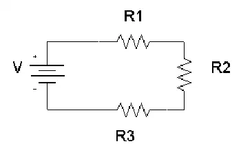
When caps are connected in series, their individual capacitance values contribute to the total equivalent capacitance. The series connection is achieved when the positive plate of one capacitor is connected to the negative plate of the subsequent capacitor. This forms a continuous path for current flow, creating a series circuit.

Calculating the total capacitance for capacitors in series is different from parallel capacitors. In a series connection, the reciprocal of the total equivalent capacitance is equal to the sum of the reciprocals of the individual capacitance values. Mathematically, this is represented as:

1/C_total = 1/C1 + 1/C2 + 1/C3 + ... + 1/Cn

Where C_total is the total equivalent capacitance, and C1, C2, C3, ... Cn are the individual capacitance values of the number of caps connected in series.

In a series connection, the electric charge stored in each capacitor is the same. However, the voltage across each capacitor varies depending on its capacitance. According to Kirchhoff's voltage law, the sum of voltages across individual capacitors must equal the applied voltage. Thus, higher capacitance values will have lower voltage drops, while lower capacitance values will have higher voltage drops.

There are both advantages and disadvantages to connecting capacitors in series. On the plus side, the voltage rating of the series connection increases, allowing the circuit to handle higher voltage levels without risking damage to the caps. This feature is particularly useful in high-voltage capacitors in series applications. Alongside capacitors, Amperes Law and Biot Savart Law provide deeper insight into the electromagnetic principles that govern current and voltage distribution.

However, there are also drawbacks to this arrangement. The total equivalent capacitance decreases as more capacitors are added to the series, which may limit the energy storage capabilities of the circuit. Moreover, in the event of a capacitor failure, the entire series connection is compromised.

Different capacitor types and values can be combined in a series configuration, but care must be taken to consider each capacitor's voltage ratings and tolerances. For instance, mixing capacitors with different dielectric materials may lead to uneven voltage distribution and reduced overall performance. Since Capacitors are essential to energy storage and timing circuits, learning their behavior in a Capacitors in Series arrangement is key for advanced electronics design.

Determining the total energy stored in a series connection of caps involves calculating the energy stored in each individual capacitor and then summing those values. The formula for energy storage in a capacitor is:

E = 0.5 * C * V^2

Where E is the energy stored, C is the capacitance, and V is the voltage across the capacitor. Calculating each capacitor's energy and adding the results can determine the total energy stored in the series connection.

Compared with parallel configurations, the total capacitance increases in parallel connections while it decreases in series. In parallel, the total capacitance is the sum of the individual capacitance values:

C_total = C1 + C2 + C3 + ... + Cn

A crucial aspect of working with capacitors in series is charge distribution. As mentioned earlier, the electric charge stored in each capacitor is the same, but the voltage distribution varies depending on the capacitance values. This characteristic influences the circuit's behaviour and must be considered when designing complex electronic systems. Uneven voltage distribution can affect the entire system's performance, making choosing caps with appropriate capacitance values and voltage ratings for a specific application is vital.

Another important factor to consider is the plate area. In general, caps with larger plate areas have higher capacitance values. Therefore, when connecting capacitors in series, it is essential to evaluate how the plate area of each capacitor influences the overall capacitance of the series connection. Understanding these factors will enable engineers and hobbyists to make informed decisions when designing and constructing electronic circuits.

Capacitors in series are versatile and valuable configurations for various electronic applications. By understanding the principles of capacitance, voltage distribution, energy storage, and the influence of dielectric materials, one can harness the full potential of capacitors connected in series. Additionally, being mindful of the advantages and disadvantages of this configuration and considering the compatibility of different capacitor types and values will enable the creation of efficient, reliable, and effective electronic circuits. As electronics evolve, they will remain critical in developing innovative devices and systems. A solid foundation in Basic Electricity makes it easier to grasp why capacitors in series lower overall capacitance but increase voltage handling.


Related Articles


View more

Electrical Energy

Electrical energy is the power derived from the movement of electrons through a conductor. It powers homes, industries, and modern technology. This form of energy can be generated from various sources, including fossil fuels, solar, wind, and hydroelectric systems.


What is Electrical Energy?

Electrical energy is the result of electric charge flow, used to perform work in countless applications across daily life and industry.

✅ Powers lighting, heating, and electronic devices across all sectors

✅ Generated by power plants from renewable and non-renewable sources

✅ Converted from and into other energy forms, like mechanical or thermal


Electrical Energy: The Fundamental Source of Power

An Electric charge is a property of certain subatomic particles (e.g., electrons and protons) which interacts with the electromagnetic field and causes attractive and repulsive forces between them. Electric charges give rise to one of the four fundamental forces of nature, and is a conserved property of matter that can be quantified. In this sense, the phrase "quantity of electricity" is used interchangeably with the phrases "charge of electricity" and "quantity of charge." There are two types of charge: we call one kind of charge positive and the other negative. Through experimentation, we find that like-charged objects repel and opposite-charged objects attract one another. Coulomb's law gives the magnitude of the force of attraction or repulsion. For a broader understanding, visit how electricity works to see how it is generated, transmitted, and used across power grids and homes.


How Electric Fields Transfer Energy Between Charges

Michael Faraday introduced the concept of the Electrical Energy field. The field force acts between two charges, in the same way that the gravitational field force acts between two masses. However, the electric field is a little bit different. Gravitational force depends on the masses of two bodies, whereas the electromagnetic force depends on the electric charges of two bodies. While gravity can only pull two masses together, the force can be attractive or repulsive. If both charges are of the same sign (e.g. both positive), there will be a repulsive force between the two. If the charges are opposite, an attractive force will exist between the two bodies (as seen in static electricity and kinetic energy). The magnitude of the force varies inversely with the square of the distance between the two bodies and is also proportional to the product of the unsigned magnitudes of the two charges. Discover how electrical load determines the demand placed on a system’s energy supply.


Electrical Energy and Voltage Explained

The electric potential difference between two points is defined as the work done per unit charge (against forces) in moving a positive point charge slowly from one point to another. Choose one point as a reference with zero potential. The electric potential at any other point equals the work required per unit charge to move a positive test charge from the reference point to that location. For isolated charges, the reference point is usually taken to be infinity. The potential is measured in volts. (1 volt = 1 joule/coulomb) The electric potential is analogous to temperature: there is a different potential at every point in space, and the potential gradient indicates the direction and magnitude of the driving force behind electric current flow. Similarly, there is an electric potential at every point in space, and its gradient indicates the direction and magnitude of the driving force behind the movement of charged energy. To understand how voltage influences electrical energy, it's essential to grasp how potential difference drives current through circuits.


Electric Current: Flow of Charge That Powers Technology

Current is a flow of electrical energy, and its intensity is measured in amperes. Examples of electric currents include metallic conduction, where electrons flow through a conductor such as a metal wire, and electrolysis, where ions (charged atoms) flow through liquids. The particles themselves often have energy to move quite slowly, while the moving electric field that drives them propagates at close to the speed of light. See energy conduction for more information. Alternating current and direct current each transfer electrical energy differently, depending on the application.

Devices that utilize charge flow principles in materials are referred to as electronic devices.

A direct current (DC) is a unidirectional flow, while an alternating current (AC) reverses direction repeatedly. The time average of an alternating current is zero, but its capability (RMS value) is not zero.

Ohm's Law is an important relationship describing the behaviour of energy, relating it to voltage. Explore the principles behind Ohm’s Law to see how voltage, current, and resistance interrelate in determining energy flow. Learn how electrical resistance affects energy loss and heat generation in systems.

For historical reasons, power is said to flow from the most positive part of a circuit to the most negative part. The current thus defined is referred to as conventional current. It is now known that, depending on the conditions, a current can consist of a flow of charged particles in either direction, or even in both directions at once. The positive-to-negative convention is widely used to simplify this situation. If another definition is used - for example, "electron current" - it should be explicitly stated.


Related Articles


View more

Impedance Definition

Impedance Definition Explained

Understanding the concept of impedance (Z) is crucial for anyone working with or studying electrical circuits, particularly those involving alternating current (AC). To grasp the intricacies of impedance, it is essential to explore its definition and the various factors that come into play.

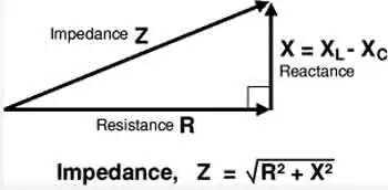
The term "impedance" is defined as the opposition that an electrical circuit presents to the flow of an alternating current (AC) or voltage. It is a complex quantity that includes both resistance and reactance components, making it vital in AC circuit analysis. Electrical impedance is essential in determining how electrical energy flows through a circuit, and it is influenced by various factors such as resistance, reactance, and frequency.

Resistance and reactance are two key elements that make up impedance. While resistance is the opposition to the flow of direct current (DC), reactance opposes the flow of AC. Reactance itself is composed of two parts: capacitive and inductive impedance. Capacitive impedance is due to the presence of capacitors in the circuit, while inductive impedance results from the presence of inductors.

Impedance is crucial in AC circuit analysis because it enables engineers and technicians to calculate how AC voltage and current behave within a circuit. This knowledge is necessary when designing and troubleshooting electrical systems. Furthermore, understanding impedance helps identify the optimal conditions for efficient energy transfer, as demonstrated by impedance matching.


Impedance matching refers to adjusting the Z of a source and load to match, maximizing the power transfer between the two. This is essential in various applications such as radio frequency (RF) communications, audio systems, and power transmission.

Calculating the total impedance (Z_total) in a circuit involves considering both the resistive and reactive components. For a series circuit, the total impedance is calculated using Ohm's law as follows:


Z_total = √ (R_total^2 + (X_L - X_C)^2)


Here, Z_total represents total impedance, R_total is the total resistance, X_L is the inductive reactance, and X_C is the capacitive reactance. In parallel circuits, the total impedance is computed by determining the reciprocal of the sum of the reciprocals of individual impedances.

Capacitive and inductive impedance play significant roles in AC circuits. As the frequency of the AC signal changes, the impedance of capacitors and inductors in the circuit also changes. As a result, capacitive impedance decreases with increasing frequency while inductive impedance increases. This characteristic can be utilized to design filters that selectively allow specific frequency ranges to pass through, shaping the output signal as desired.

Impedance spectroscopy is a technique that examines the Z of a material or device over a range of frequencies. This process provides valuable information on the electrical properties and behaviour of the material, enabling researchers and engineers to gain insight into various phenomena such as conductivity, dielectric properties, and electrochemical reactions. This knowledge can be applied to optimize the design and performance of various materials and devices.

Impedance definition and its various aspects, including electrical impedance, complex impedance, impedance matching, and impedance spectroscopy, are essential to understanding AC circuit analysis and the behaviour of electrical circuits in different applications. By examining the interplay of resistance and reactance and the influence of electric and magnetic fields, engineers can design and optimize circuits to ensure maximum efficiency and functionality.

View more

Ampere's Law Explained

Ampere’s Law describes the relationship between magnetic fields and electric currents, a fundamental concept in electromagnetism. It explains how current produces a magnetic force, guiding the design of circuits, solenoids, coils, and transformers in electrical engineering.


What is Ampere’s Law?

Ampere's Law is a fundamental principle in electromagnetism that describes the relationship between electric current and the resulting magnetic field.

✅ It states that the magnetic field around a closed path is proportional to the electric current passing through it.

✅ It is a fundamental principle of electromagnetism, linking current and magnetic flux.

✅ Used in analyzing coils, solenoids, transformers, and magnetic circuits.

Named after the French physicist André-Marie Ampère, this powerful principle helps us understand the behaviour of magnetic fields generated by electric currents. It is crucial to develop the numerous technologies we use on a daily basis. Understanding Ampere's Law is easier when explored alongside related concepts in basic electricity, which provide the foundation for electrical theory.

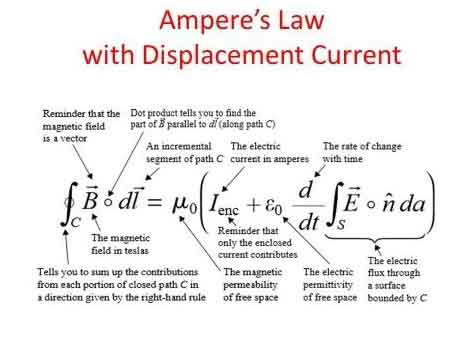
The principle states that the line integral of a magnetic field (B) around a closed loop is equal to the product of the permeability of free space (μ₀) and the net electric current (I) passing through the loop. This can be mathematically represented as:

∮ B⋅dl = μ₀I


Ampere’s Law at a Glance

Aspect Explanation Example / Application
Definition Magnetic field around a closed loop is proportional to the net electric current passing through it. Helps calculate fields in wires, coils, solenoids.
Formula ∮ B · dl = μ₀I (line integral of magnetic field equals permeability × current). Used in physics and engineering calculations.
Relation to Biot-Savart Law Both describe magnetic fields from current. Biot-Savart handles complex geometries; Ampere’s Law suits symmetrical setups. Magnetic field around a straight wire vs. irregular current paths.
Relation to Faraday’s Law Ampere’s Law: current → magnetic field. Faraday’s Law: changing magnetic field → induced EMF. Motors, generators, induction coils.
Role in Maxwell’s Equations One of the four fundamental equations of electromagnetism. Describes interaction of electric and magnetic fields.
Key Devices Guides design of solenoids, transformers, inductors, motors, and generators. Power systems, telecommunications, energy conversion.
Real-World Impact Essential to modern technology relying on electromagnetism. Smartphones, computers, power grids, antennas.


Ampere’s Law and Magnetism

The principle can be applied to determine the magnetic field around current-carrying wires and other conductive materials, as well as within various electrical systems. It is an essential part of Maxwell's equations, a set of four equations that serve as the foundation of classical electromagnetism. These equations relate electric and magnetic fields to their sources (electric charges and currents) and describe how they propagate through space. The connection between electricity and magnetism is central to electromagnetism, where Ampere’s Law works hand-in-hand with Faraday’s Law to explain induction.

It calculates magnetic fields through the Biot-Savart Law, a mathematical expression that relates the magnetic field produced by a steady electric current to the current's geometry. Both principles have specific applications, with the Biot-Savart Law being more suitable for cases with intricate current configurations. At the same time, it is typically employed when dealing with symmetrical setups.

Ampere’s Law has numerous real-life applications, especially in developing and understanding devices and systems that involve electromagnetism. For example, it is used in the design of transformers, inductors, and solenoids, as well as in various applications such as telecommunications systems, motors, and generators. By applying it, engineers can predict and control the magnetic fields generated in these devices, ensuring they function optimally and efficiently.


Gauss’ Law and Electric Fields Around a Circle of Radius

When studying electromagnetism, a common problem is analyzing the behavior of electric fields around a symmetric object, such as a circle of radius r or a sphere. Gauss’ Law is especially powerful in such cases, because it states that the electric flux through a closed surface is proportional to the net charge enclosed. This means the distribution of field lines can be calculated without solving complex integrals directly.

For a uniformly charged circle of radius r, the electric field at a point along the axis can be derived by considering the superposition of contributions from each charge element. The result reveals that the electric field depends on both the radius of the circle and the distance from the observation point. This demonstrates how Gauss’ Law simplifies problems with high symmetry.

Mathematically, the relationship is expressed as:

∮ E · dA = Q / ε₀

Here, E represents the vector field of the electric field, dA is the infinitesimal area vector on the closed surface, Q is the enclosed charge, and ε₀ is the permittivity of free space. By applying this principle, one can determine that electric fields radiate symmetrically outward from charges, with strength diminishing with distance according to the geometry of the surface considered.

The application of Gauss’ Law in analyzing a circle of radius r is connected to Ampere’s Law, as both emphasize symmetry and integration around closed paths. Where Ampere’s Law links magnetic fields to current, Gauss’ Law links electric fields to charge, and together they form part of Maxwell’s equations, the foundation of electromagnetism.


Relationship between Ampere's Law and Faraday's Law

The relationship between Ampere's Law and Faraday's Law of electromagnetic induction is apparent in the phenomenon of electromagnetic induction itself. When a changing magnetic field induces an electric current in a conductive material, the resulting magnetic field generated by this electric current, in turn, affects the overall magnetic field. It helps us understand how these interacting magnetic fields behave and influence each other.

Ampere's Law and its applications in various devices and systems enable numerous technological advancements. For instance, when designing motors and generators, engineers can utilize the principle to optimize the magnetic field within the device, resulting in higher efficiency and improved performance. Ampere’s Law is also linked to the behavior of capacitance and inductance, both of which are essential in circuits and energy storage systems.

In the telecommunications realm, it helps explain the propagation of electromagnetic waves in cables and antennas. It enables engineers to design systems that minimize signal loss and maximize data transfer rates, ensuring that our smartphones, computers, and other devices remain connected and up-to-date.

By understanding the magnetic field lines and the interaction between electric current and magnetic fields, Ampere's Law opens doors to scientific discovery and innovation in numerous fields. From determining the magnetic field at a distance to the thumb rule and hand rule applications, this fundamental principle plays a crucial role in shaping the world of electromagnetism and the technology that surrounds us.


Electromagnetism

It is a cornerstone of electromagnetism that helps us understand the relationship between electric current and how it creates a magnetic field. It is a vital component of Maxwell's equations and intricately connected to other principles, such as Faraday's Law and Biot-Savart's Law. Ampere's Law has numerous applications in real-life scenarios and is essential for the functioning of many devices and systems that rely on electromagnetism. Its significance in the development of technology cannot be overstated, as it continues to drive scientific discovery and innovation. For students exploring fundamentals, the history of concepts like what is electricity and its evolution in electricity history provides valuable context to Ampere’s discoveries.


How does Ampere’s Law relate to Faraday's Law and Biot-Savart Law?

They are all essential principles in electromagnetism that describe various aspects of the interaction between electric currents and magnetic fields. Although each addresses different aspects, these are interrelated, forming a more comprehensive understanding of electromagnetism.

It describes the relationship between an electric current and its generated magnetic field. Mathematically, it states that the line integral of the magnetic field (B) around a closed loop is proportional to the net electric current (I) passing through the loop:

∮ B⋅dl = μ₀I

Ampere’s Law is useful for calculating magnetic fields in highly symmetrical situations, such as around straight wires, loops, or solenoids.

Faraday's Law: Faraday's Law of Electromagnetic Induction describes how a changing magnetic field induces an electromotive force (EMF) in a conductor. Mathematically, it states that the induced EMF is proportional to the rate of change of the magnetic flux (ΦB) through a closed loop formed by the conductor:

EMF = -dΦB/dt

Faraday's Law is fundamental to understanding the operation of devices such as generators, transformers, and induction motors, which rely on converting mechanical and electrical energy.

The Biot-Savart Law calculates the magnetic field at any point in space due to a specific current distribution. Mathematically, it can be expressed as:

dB = (μ₀ / 4π) * (Idl × r̂) / r²

The Biot-Savart Law is particularly useful for calculating magnetic fields in complex current configurations without symmetry.


Ampere's Law and Biot-Savart Law

Ampere's Law and Biot-Savart Law: Both deal with the magnetic field generated by an electric current. While the first is useful for calculating magnetic fields in symmetric situations, the Biot-Savart Law applies to a wider range of configurations, including those with intricate geometries. It can be derived from the Biot-Savart Law for specific symmetric situations.


Ampere's Law and Faraday's Law

Ampere's Law and Faraday's Law: These laws are related through Maxwell's equations, which connect electric and magnetic fields. While the first deals with the magnetic field generated by a steady electric current, Faraday's Law deals with the induced EMF resulting from a changing magnetic field. Both laws contribute to our understanding of electromagnetic phenomena and play a role in operating devices that rely on electromagnetism.

The Biot-Savart Law enables us to determine the magnetic field generated by a specific current distribution. Faraday's Law describes how a changing magnetic field can induce an EMF. In cases where the magnetic field changes due to a varying current, the Biot-Savart Law can be used to calculate the magnetic field, and then Faraday's Law can be applied to determine the induced EMF.

All three are interconnected principles in electromagnetism, each addressing a specific aspect of the interaction between the electric current and the electric field. Together, these form a more comprehensive understanding of electromagnetic phenomena and provide a basis for analyzing and designing various devices and systems that rely on electromagnetism.


Related Articles


View more

Electrical Resistance Explained

Electrical resistance is the opposition to the flow of electric current in a material. It is measured in ohms (Ω) and depends on the conductor’s length, thickness, material, and temperature.


What is Electrical Resistance?

Electrical resistance is a fundamental concept in engineering that defines how much a material opposes the flow of electric current. Measured in ohms (Ω), resistance (Ω) plays a crucial role in circuit design, power distribution, and electronic applications.

✅ Measured in ohms (Ω) and calculated using Ohm’s Law

✅ Influenced by material, length, area, and temperature

✅ Key factor in circuit safety, design, and energy loss


Think of electricity moving like water through a pipe. If the pipe is narrow or obstructed, less water flows through it. Similarly, in a wire or conductor, certain materials make it harder for electrons to move freely. This obstruction results in energy loss, often seen as heat.

The ease or difficulty of electric charge movement depends on the conductivity of a material. Metals like copper allow current to flow easily, while rubber or glass inhibit it entirely. This behavior plays a key role in how systems are designed and protected. Discover how resistors are used in circuits to manage voltage and protect components by providing controlled resistance.


Electrical Resistance – Example Values by Material/Component

Material/Component Approx. Resistance Notes
Copper wire (1 meter, 1mm²) ~0.017 ohms Very low resistance, ideal for conductors
Aluminum wire (1m, 1mm²) ~0.028 ohms Higher resistance than copper
Iron wire (1m, 1mm²) ~0.10 ohms Often used in heating elements
Nichrome wire (1m, 1mm²) ~1.10 ohms High-resistance alloy used in toasters and heaters
Human body (dry skin) 1,000–100,000 ohms Varies greatly with moisture and contact
Incandescent light bulb ~240 ohms (cold) Resistance increases when hot
Resistor (carbon film) Fixed (e.g., 220 ohms) Used to control current in circuits
Air (dry) ~1 trillion ohms (insulator) Excellent natural insulator unless ionized
Superconductor 0 ohms Only at extremely low temperatures (near absolute zero)


Electrical Resistance Definition

Several factors affecting electrical resistance include the type of material, temperature, and the dimensions of the conductor. When an electric charge moves through a material, its ease of flow depends on the material’s conductivity. A high-conductivity material allows charges to move more freely, resulting in lower resistance. The resistance of a conductor increases with its length and decreases with its cross-sectional area. Therefore, the resistance of a wire is directly related to both its physical properties and the material from which it is made. The resistance of a conductor depends heavily on its length and cross-sectional area, as outlined in our resistance formula breakdown.

This opposing property is quantified using Ohm’s Law:

R = V / I

Where:

  • R is the resistive value in ohms

  • V is voltage (volts)

  • I is current (amperes)

Another useful expression involves material properties:

R = ρ × (L / A)

Where:

  • ρ is resistivity (material-specific)

  • L is length

  • A is cross-sectional area

These formulas show that the longer or thinner the conductor, the harder it is for current to move through it.


Unit of Electrical Resistance – The Ohm (Ω)

The ohm is the SI unit of resistance, named after German physicist Georg Ohm. One ohm is defined as the resistance between two points of a conductor when a potential difference of one volt causes a current of one ampere to flow.

Common multiples:

  • kΩ (kilo-ohm) = 1,000 ohms

  • MΩ (mega-ohm) = 1,000,000 ohms

Resistance can be measured using a multimeter, and is especially important in designing and troubleshooting power  and electronic circuits. To understand how voltage and resistance interact in a circuit, see our guide on Ohm’s Law.


Ohm’s Law and Circuit Function

Ohm’s Law helps us understand how voltage, current, and resistance relate. For example:

  • Increase the resistive load, and current drops.

  • Increase voltage with fixed resistance, and current rises.

These principles help control energy flow, prevent overloads, and design efficient systems.


Measuring and Expressing Opposition

The ohm (Ω) is the standard unit used to quantify this phenomenon. One ohm means that a current of one ampere flows when one volt is applied. Components with fixed values, like resistors, are labelled accordingly—e.g., 100 Ω, 1 kΩ, or 1 MΩ.

To measure the current-limiting capacity of a material, a digital multimeter is used. It applies a small voltage and calculates the resulting current flow to determine the opposition level. If you're working with different wire types, explore the unit of electrical resistance for conversion insights and resistance ranges.


Real-World Examples of Resistance

  • Heating Elements: Toasters, ovens, and electric heaters utilize high-resistance materials, such as nichrome wire.

  • Power Transmission: Long-distance wires are designed with low resistance to reduce energy loss as heat.

  • Electronic Components: Resistors regulate current in circuits, protecting components from overload.

For real-world scenarios involving current flow, our article on voltage drop explains how resistance affects electrical efficiency over distance.


Factors Affecting Electrical Resistance

  • The resistance of a conductor depends on:

    • Material – copper vs. aluminum vs. nichrome

    • Length – longer wires restrict current more

    • Thickness – wider wires allow easier flow

    • Temperature – many materials resist current more when heated

    Thus, the resistance of a wire can vary dramatically depending on where and how it’s used. Materials with high conductivity (like silver or copper) allow electrons to move with minimal restriction, whereas poor conductors like rubber greatly hinder charge movement.


Superconductors – Zero Resistance?

In some materials, when cooled to extremely low temperatures, resistance drops to zero. These superconductors enable electricity to flow without energy loss, but their use is limited to specialized fields, such as MRI machines or experimental power lines, due to cost and cooling requirements.


Frequently Asked Questions


What causes electrical resistance?

It results from collisions between electrons and atoms in a conductor, which convert energy into heat.


What is the formula for calculating it?

 R = V/I or R = ρ × (L / A)


How is it measured?

With a multimeter in ohms (Ω), using a small test voltage and measuring current. Learn how instruments like a digital multimeter are used to measure opposition to current flow in electrical systems.


Why is this concept important?

It controls current flow, prevents damage, and enables functions like heating or dimming.


Can resistance ever be zero?

Yes—in superconductors under specific extreme conditions.

Electrical resistance is a foundational concept in understanding how electricity behaves in materials and systems. From household wiring to high-voltage power lines and sensitive electronics, it plays a crucial role in determining safety, efficiency, and performance. For a broader view on electric flow and material response, read about electrical conductivity and current electricity.


Related Articles


View more

Sign Up for Electricity Forum’s Newsletter

Stay informed with our FREE Newsletter — get the latest news, breakthrough technologies, and expert insights, delivered straight to your inbox.

Electricity Today T&D Magazine Subscribe for FREE

Stay informed with the latest T&D policies and technologies.
  • Timely insights from industry experts
  • Practical solutions T&D engineers
  • Free access to every issue

Download the 2025 Electrical Training Catalog

Explore 50+ live, expert-led electrical training courses –

  • Interactive
  • Flexible
  • CEU-cerified