Capacitance Definition

By R.W. Hurst, Editor


Capacitance definition clarifies how a capacitor stores electric charge per unit voltage, measured in farads, influenced by plate area and dielectric, shaping reactance, energy storage, and signal behavior in AC and DC circuits.


What Is the Capacitance Definition?

Capacitance is a component's ability to store electric charge per unit voltage, measured in farads.

✅ Measured in farads with C = Q/V

✅ Depends on plate area, spacing, and dielectric

✅ Affects reactance, filtering, and energy storage


Capacitance Definition

Another important property in AC electronic circuits, besides resistance and inductance, is capacitance. Capacitance is measured in units. The unit of capacitance is the farad. While inductance is represented in a circuit by a coil, capacitance is represented by a capacitor. In its most basic form, the capacitor is constructed of two parallel plates separated by a nonconductor, called a dielectric. In an electrical circuit, a capacitor serves as a reservoir or storehouse for electricity. For a clear overview of device construction and function, see what is a capacitor to relate these fundamentals.


Capacitance Definition in Direct Current

When a capacitor is connected across a source of direct current, such as a storage battery in the circuit shown in Figure 1A, and the switch is then closed, the plate marked B becomes positively charged, and the A plate negatively charged. Current flows in the external circuit when the electrons move from B to A. The current flow in the circuit is at a maximum when the switch is closed, but it continually decreases until it reaches zero. The current becomes zero as soon as the difference in voltage of A and B becomes the same as the applied voltages of the battery. The plates remain charged if the switch is opened, as shown in Figure 1B. Once the capacitor is shorted, it will discharge quickly as shown in Figure 1C. It should be clear that when the capacitor is being charged or discharged, there is current in the circuit, even though the gap between the capacitor plates breaks the circuit. Current is present only during the time of charge and discharge, which is usually short. A broader introduction is provided in what is capacitance for context on this charging behavior.


Fig 1 - Capacitance Definition in direct current.

The RC Time Constant The time required for a capacitor to attain a full electrical charge is proportional to the capacitance and the resistance of the circuit. The resistance of the circuit introduces the element of time into the charging and discharging of a capacitor. When designing filters or timing networks, combining devices affects total C, and capacitance in parallel explains how values add.

When a capacitior charges or discharges through a resistance, a certain amount of time is required for a full charge or discharge. The voltage across the capacitor will not change instantaneously. The rate of charging or discharging is determined by the circuit's time constant. The time constant of a series RC (resistor/ capacitor) circuit is a time interval that equals the product of the resistance in ohms and the capacitance in farad and is symbolized by the greek letter tau (τ). For a concise refresher on definitions and symbols, see capacitance before applying the time constant formula.

τ = RC

The time in the formula is required to charge to 63% of the voltage of the source. The time needed to bring the amount of charge to about 99% of the source voltage is approximately 5 τ. Figure 2 illustrates this relationship of the time constant characteristics of charging. In network calculations, series combinations behave differently, and capacitance in series outlines the reciprocal method used.


Fig 2 - Capacitance Definition discharge curve.

When asked for a capacitance definition, I often explain that capacitance is the measure of a capacitor’s ability to store electric charge. The symbol used for capacitance is the letter C. You can measure the electric potential of the dielectric material in an electronic component where it may store energy. For details on nomenclature and SI units, consult the unit of capacitance and confirm typical values.

As can be seen from the time constant illustration, there can be no continuous movement of direct current through a capacitor. A good capacitor will block
direct current and will pass the effects of pulsing DC or alternating current. For application examples across power supplies, signal coupling, and filtering, explore capacitors to see practical implementations.


Related Articles

Related News

Capacitance in Parallel Explained

Capacitance in parallel occurs when capacitors are connected side by side, and their values add together. This increases total capacitance, ensures stable voltage, supports efficient charge distribution, and is essential in electronics, energy storage, and reliable circuit design.


What is Capacitance in Parallel?

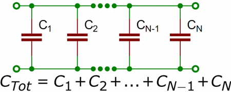
Capacitance in parallel occurs when capacitors are connected across the same two points in a circuit, causing their capacitance to add up:

✅ Increases total capacitance by summing all capacitor values

✅ Improves energy storage and voltage regulation in circuits

✅ Common in AC and DC applications for a consistent charge supply

To learn the fundamentals, see what is capacitance, which explains how capacitors store charge, the role of farads, and why this property is essential in circuits and energy storage.


Understanding Parallel Capacitor Behavior

When capacitors are connected in parallel, the effective plate area increases, and the total capacitance is the sum of the individual capacitances. Figure 1 shows a simplified parallel circuit. The total charging current from the source divides at the junction of the parallel branches. To fully understand how capacitors behave in parallel, it helps to revisit the basics of what is a capacitor and how capacitance works in circuits. 


Fig. 1 - Simplified parallel circuit.


There is a separate charging current through each branch, allowing a different charge to be stored by each capacitor. Using Kirchhoff’s current law, the sum of all the charging currents is then equal to the total current. The sum of the charges (Q) on the capacitors is equal to the total charge on the capacitors. The voltages (E) across all of the parallel branches are equal. With all of this in mind, a general equation for capacitors in parallel can be determined as:

QT = Q1 + Q2 + Q3

Because Q = CE: CTET = C1E1 + C2E2 + C3E3

Voltages can be factored out because:

ET = E1 + E2 + E3

Leaving us with the equation for capacitors in parallel:

CT = C1 + C2 + C3

Consider the following example:

If C1 = 330μF, C2 = 220μF

Then CT = 330μF + 220μF = 550μF

To calculate the total capacitance in a parallel combination, you simply add the values of the individual capacitors together. This method is straightforward and differs from series connections, where the reciprocal of each capacitor must be used. The total increases with the number of capacitors added in parallel, making this configuration ideal for applications that require higher capacitance. When designing circuits, understanding how a parallel combination enhances energy storage compared to a series connection is crucial for selecting the optimal number of capacitors to achieve the desired performance. For a detailed breakdown of how capacitance is measured, check out the unit of capacitance to understand farads and their practical conversions.

Since voltage remains constant across parallel capacitors, a firm grasp of what is voltage and its behavior in different configurations is essential.


Capacitance in Alternating Current

If a source of alternating current is substituted for the battery, the capacitor acts quite differently than it does with direct current. When an alternating current is applied in the circuit, the charge on the plates constantly changes. [Figure 2] This means that electricity must flow first from Y clockwise around to X, then from X counterclockwise around to Y, then from Y clockwise around to X, and so on. Although no current flows through the insulator between the plates of the capacitor, it constantly flows in the remainder of the circuit between X and Y. In a circuit in which there is only capacitance, current leads the applied voltage, as contrasted with a circuit in which there is inductance, where the current lags the voltage. Capacitors in AC circuits are deeply influenced by alternating current, where the current leads the voltage due to capacitive reactance.


Fig. 2 - Capacitor in an AC circuit.

The parallel connection rule CT = C1 + C2 + C3 reflects the broader principles of resistances in parallel, though capacitance behaves in an additive way instead of being reciprocal.


Capacitive Reactance Xc

The effectiveness of a capacitor in allowing an AC flow to pass depends upon the capacitance of the circuit and the applied frequency. To what degree a capacitor allows an AC flow to pass depends largely upon the capacitive value of the capacitor, given in farads (F). The greater the capacitance, the greater the number of electrons, measured in coulombs, necessary to bring the capacitor to a fully charged state. Once the capacitor approaches or actually reaches a fully charged condition, the polarity of the capacitor will oppose the polarity of the applied voltage, essentially acting then as an open circuit.

To further illustrate this characteristic and how it manifests itself in an AC circuit, consider the following:
If a capacitor has a large capacitive value, a high-frequency current can alternate through it without the capacitor ever reaching a full charge. In this case, the capacitor may offer very little resistance to current.

However, the smaller the capacitance, the fewer electrons are required to bring it up to a full charge, and it is more likely that the capacitor will build up enough of an opposing charge to present significant resistance, possibly behaving like an open circuit. Understanding Kirchhoff’s Law helps explain how current divides among parallel capacitors and supports accurate calculations.


Comparison With Series Capacitance

Understanding the difference between series and parallel capacitance is critical for circuit design:

Configuration Total Capacitance Voltage Behavior Current Behavior
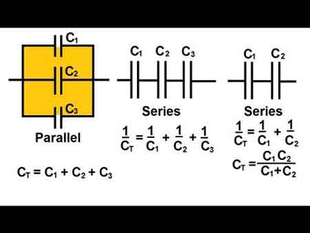
Parallel Adds directly: CT = C1 + C2 + ... Same across all components Divides among branches
Series Inverse sum: 1/CT = 1/C1 + 1/C2 + ... Divides across components Same through all components
  • Parallel is best when you want more capacitance and voltage stability.

  • Series is used when you need a lower total capacitance or to increase voltage tolerance.

To explore how capacitors behave when connected end-to-end, visit capacitance in series, which explains the reciprocal formula and voltage behavior.


Practical Design Considerations

  • Voltage Rating: In parallel, all capacitors share the same voltage. The lowest voltage rating among capacitors determines the safe operating voltage of the group.

  • Physical Size: Adding more capacitors increases board space. Designers must balance performance with space constraints.

  • Energy Storage: Parallel configurations store more energy, making them ideal for power supplies, smoothing circuits, and buffering in audio and RF systems.

Real-world circuit design also requires familiarity with types of capacitors, as their materials and tolerances affect total capacitance and performance.


Real-World Applications of Parallel Capacitors

  • Power Supply Smoothing: Bulk capacitors in parallel stabilize the DC output.

  • Decoupling Noise: Small-value capacitors placed in parallel with larger ones eliminate high-frequency interference.

  • Tuning Circuits: In radio circuits, variable capacitors, when used in parallel with fixed ones, help tune specific frequencies.

For a broader context, you can explore how electrical resistance and reactive power relate to capacitive elements in AC power systems.


Related Articles


View more

How Electricity Works

Electricity works by moving electrons through a conductor, creating an electric current. Power stations generate electricity, which travels through wires to homes and businesses. This flow powers devices, lights, and machines, making modern life possible through electric energy and circuits.


Explain How Electricity Works

✅ Electrons move through conductors to create electric current

✅ Power plants convert energy into usable electricity

✅ Electrical systems distribute power to homes, industries, and devices


What Is Electricity and Where Does It Come From?

Electricity energy is as common to us as running water in many areas, especially in industrialized countries. Despite this, there is a great deal of ignorance about this mysterious force and its origin. 

  • The concept of voltage is central to how electricity flows, as it represents the electrical pressure that pushes electrons through a circuit.

  • Understanding alternating current is essential, as it's the form of electricity most commonly delivered to homes and businesses.


Atomic Structure and the Nature of Electric Charge

If you can picture an atom as a sphere, imagine in the nucleus, in the centre, that contains at least one proton and at least one neutron. The proton is positively charged. In orbit around the nucleus is at least one electron, which is negatively charged. The reason they have these opposite charges takes us deep into the realm of quantum physics. We know that the neutron is made up of quarks and the electron is an elementary particle (it is not made up of anything and is a particle in its own right), but the reason why they have opposite charges is a matter beyond my meagre capabilities and, in any case, this area is at the fringes of human knowledge.


Electron Movement and Free Charge in Conductive Materials

Atoms may contain several protons and electrons. This variation is what distinguishes one element from another. Although described as sub-atomic particles, electrons have the properties of both particles and waves when it comes to fields of magnetism in electric circuits. In theory, at least, they could be both at the same time. If you want to know what materials conduct electricity well, see our overview of conductors, which explains how they allow electrons to move freely.

If an atom has no electric charge, i.e. it is neutral, then it contains the same number of protons as electrons. In some materials, most notably metals, the electrons' orbits around the nucleus are quite loose, allowing them to spin away from the atom. When this happens, the atom becomes positively charged because protons are in the majority within the atom. A free electron can join another atom. When this occurs, then the new host atom becomes negatively charged because the electrons are in the majority (assuming the atom was neutral in the first place). Devices like ammeters and multimeters are essential for measuring electrical current and diagnosing circuit performance.


Potential Difference and the Creation of Electric Current

There are many views about the subject. If you ask science experts on YouTube to show how static electricity works, they will report that opposites attract. The greater the difference between the number of electrons and protons, the greater the attraction will be. This is called a potential difference. If we can therefore manage to produce a negative charge at one end of a copper wire and a positive charge at the other end, free electrons would move towards the positive end. As electrons leave those atoms nearest the positive end, they leave behind positively charged atoms. Electrons from neighbouring atoms will be attracted towards these positive atoms, thus creating yet more positive atoms in their wake. This continuing transfer of electrons is called current. The greater the potential difference, or voltage, measured in its unit, the greater the force of the flow of electrons, or current.


Understanding Direct and Alternating Current (DC vs AC)

Electric power can be supplied as direct current (e.g. from car batteries for lighting) or as alternating current (e.g. household mains). To explore the differences between current types, read our guide on the difference between AC and DC, which explains why each type is used in different applications.


How Transformers Adjust Voltage for Power Distribution

Often, an electrical product requires a different voltage from the one supplied by the mains electric power. In these cases, a transformer rating is required. The use of transformers is very common along power lines and in electrical devices. In addition to the step-up transformers that increase voltage, transformers can also reduce voltage. These step-down transformers can be found at utility substations where the very high voltages required to push electrons through long transmission wires are reduced for local consumption.


Related Articles


View more

Understanding Inductance

Inductance
Michael Faraday discovered that by moving a magnet through a coil of wire, a voltage was induced across the coil. If a complete circuit was provided, then a current was also induced. The amount of induced voltage is directly proportional to the rate of change of the magnetic field with respect to the coil. The simplest of experiments can prove that when a bar magnet is moved through a coil of wire, a voltage is induced and can be measured on a voltmeter. This is commonly known as Faraday’s Law or the law of electromagnetic induction, which states:

The induced emf or electromagnetic force in a closed loop of wire is proportional to the rate of change of the magnetic flux through a coil of wire.

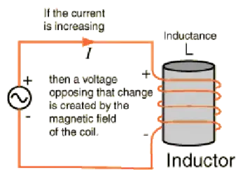
Conversely, current flowing through a coil of wire produces a magnetic field. When this wire is formed into a coil, it then becomes a basic inductor. The magnetic lines of force around each loop or turn in the coil effectively add to the lines of force around the adjoining loops. This forms a strong magnetic field within and around the coil. Figure 1A, illustrates this idea of a coil of wire strengthening a magnetic field. The magnetic lines of force around adjacent loops are deflected into an outer path when the loops are brought close together. This happens because the magnetic lines of force between adjacent loops are in opposition with each other. The total magnetic field for the two loops close together, the strength of the magnetic field will increase. Figure 10-118C illustrates the combined effects of many loops of a coil. The result is a strong electromagnet.


Fig. 1 - Many loops of a coil.


The primary aspect of the operation of a coil is its property to oppose any change in current through it. This property is called inductance. When current flows through any conductor, a magnetic field starts to expand from the center of the wire. As the lines of magnetic force grow outward through the conductor, they induce an emf in the conductor itself. The induced voltage is always in the direction opposite to the direction of the current flow. The effects of this countering emf are to oppose the immediate establishment of the maximum current. This effect is only a temporary condition. Once the current reaches a steady value in the conductor, the lines of magnetic force will no longer be expanding and the countering emf will no longer be present.

At the starting instant, the countering emf nearly equals the applied voltage, resulting in a small current flow. However, as the lines of force move outward, the number of lines cutting the conductor per second becomes progressively smaller, resulting in a diminished counter emf. Eventually, the counter emf drops to zero and the only voltage in the circuit is the applied voltage and the current is at its maximum value.


The RL Time Constant

Because the inductors basic action is to oppose a change in its current, it then follows that the current cannot change instantaneously in the inductor. A certain time is required for the current to make a change from one value to another. The rate at which the current changes is determined by a time constant represented by the greek letter tau (τ). The time constant for the RL circuit is:


In a series RL circuit, the current will increase to 63% of its full value in 1 time constant after the circuit is closed. This build up of course is similar to the build up of voltage in a capacitor when charging an RC circuit. Both follow an exponential curve and reach 99% value after the 5th time constant. Figure 2 illustrates this characteristic.


Physical Parameters
Some of the physical factors that affect inductance are:

  1. The number of turns: Doubling the number of turns in a coil will produce a field twice as strong, if the same current is used. As a general rule, the inductance varies as the square of the number of turns.
  2. The cross-sectional area of the coil: The inductance of a coil increases directly as the cross-sectional area of the core increases. Doubling the radius of a coil increases the inductance by a factor of four.
  3. The length of a coil: Doubling the length of a coil, while keeping the same number of turns, halves the value of inductance.
  4. The core material around which the coil is formed: Coils are wound on either magnetic or nonmagnetic materials. Some nonmagnetic materials include air, copper, plastic, and glass. Magnetic materials include nickel, iron, steel, or cobalt, which have a permeability that provides a better path for the magnetic lines of force and permit a stronger magnetic field. 


Self-Inductance
The characteristic of self-inductance was summarized by German physicist Heinrich Lenz in 1833 and gives the direction of the induced electromotive force (emf) resulting from electromagnetic induction. This is commonly known as Lenz’s Law, which states:

"The emf induced in an electric circuit always acts in such a direction that the current it drives around a closed circuit produces a magnetic field which opposes the change in magnetic flux."

Self inductance is the generation of a voltage in an electric circuit by a changing current in the same circuit. Even a straight piece of wire will have some degree of inductance because current in a conductor produces a magnetic field. When the current in a conductor changes direction, there will be a corresponding change in the polarity of the magnetic field around the conductor. Therefore, a changing current produces a changing magnetic field around the wire.

To further intensify the magnetic field, the wire can be rolled into a coil, which is called an inductor. The changing magnetic field around the inductor induces a voltage across the coil. This induced electromotive force is called self-inductance and tends to oppose any change in current within the circuit. This property is usually called inductance and symbolized with the letter L. 


View more

What is an Electrical Circuit?

An electrical circuit is a closed loop that allows electric current to flow through conductors, power sources, and loads. Circuits connect electrical devices, enable energy transfer, and ensure safe operation in homes, industries, and power systems.


What is an Electrical Circuit?

An electrical circuit is a path through which electricity flows from a power source to one or more devices that are connected.

✅ Provides controlled current flow through conductors

✅ Powers electrical devices safely and efficiently

✅ Includes sources, loads, and protective components

Gaining a grasp of the basic electricity of electrical circuits, including series and parallel configurations, voltage, current, resistance, Ohm's Law, and circuit analysis techniques, is vital for anyone interested in electronics, electrical engineering, or the inner workings of modern technology.


Core Components & Function

In order to understand what an electrical circuit is, one must appreciate that, 

At its core, an electrical circuit is a closed loop or pathway that facilitates the flow of electric current. This concept is essential in electronics and electrical engineering, as it provides the basis for the operation of everyday items, including smartphones, computers, and home appliances.

Within an electrical circuit, components are connected via conductive materials, such as wires, which enable the movement of electrons from a power source to other components and back.

The primary components of an electrical circuit include a power source (e.g., a battery or power supply unit), conductive materials (typically wires), a load (such as a resistor, motor, or light bulb), and a control element (for example, a switch). The power source supplies the voltage necessary for electric current flow, while the load transforms electrical energy into other forms, such as light or heat. Meanwhile, the control element permits the user to initiate or halt the flow of electrons, effectively turning a device on or off.

  • For students, a simple example is a battery connected to an LED, which demonstrates how electricity creates light.

  • For professionals, an industrial motor powered by a control circuit shows how electrical energy drives large-scale equipment.


Circuit Types (Series vs. Parallel)

Electrical circuits can be classified into three main types: series, parallel, and combination circuits.

  • Series circuits connect components end-to-end, allowing current to flow sequentially through each one. Example: holiday string lights, where a single bulb outage can disrupt the entire circuit.

  • Parallel circuits enable current to flow through multiple paths. Example: household wiring, where turning off one light doesn’t affect others.

  • Combination circuits mix both series and parallel configurations to handle more complex systems.


Fundamental Laws (Ohm’s Law, Kirchhoff’s Laws)

A fundamental understanding of voltage, current, and resistance is crucial for comprehending electrical circuit operations.

Voltage, the driving force that propels electric charge through a circuit, and current, the flow of electric charge measured in amperes (A), are closely related to resistance. Resistance, expressed in ohms (Ω), represents the opposition to the flow of current. These elements are interconnected through Ohm's law, which states that the voltage across a conductor is directly proportional to the current it carries and inversely proportional to its resistance: V = IR, where V represents voltage, I denotes current, and R represents resistance. Understanding how current creates magnetic fields is explained by Ampere's Law, which forms the basis for analyzing electromagnetism in electrical circuits.

Circuit analysis determines the current, voltage, and power associated with each component in an electrical circuit. Techniques such as Kirchhoff's Law of voltage and current, Thevenin's theorem, and Norton's theorem are employed to analyze and resolve electrical circuit issues. These methods enable engineers to design and troubleshoot electronic devices and systems effectively.


Thevenin's Theorem

Thevenin's theorem is a fundamental principle in electrical engineering and circuit analysis. It is a powerful technique to simplify complex linear circuits, making it easier to analyze and calculate the current, voltage, and power across specific components. The theorem is named after the French engineer Charles Léonard Siméon Thévenin, who proposed it in 1883.


Thevenin's theorem states that any linear, active, bilateral network containing voltage sources, current sources, and resistors can be replaced by an equivalent circuit consisting of a single voltage source (called Thevenin's voltage, Vth) in series with a single resistor (called Thevenin's resistance, Rth) connected to the terminals of the original circuit. This simplified circuit, known as the Thevenin equivalent circuit, can then be used to analyze the behaviour of the original circuit with a specific load connected to its terminals.

Steps to apply Thevenin’s theorem:

  1. Identify the portion of the circuit you want to simplify and the terminals where the load will be connected.

  2. Remove the load from the terminals (if present) and leave the terminals open-circuited.

  3. Calculate the open-circuit voltage across the terminals. This value is Thevenin's voltage (Vth).

  4. Calculate the equivalent resistance seen from the open-circuited terminals with all independent voltage sources replaced by short circuits (zero resistance) and all independent current sources replaced by open circuits (infinite resistance). This value is Thevenin's resistance (Rth).

  5. Create the Thevenin equivalent circuit using the calculated Vth and Rth values, then connect the original load across the terminals.

Once the Thevenin equivalent circuit is determined, you can easily analyze the circuit's behaviour and calculate the current through the load, the voltage across the load, or even the power delivered to the load. This technique is particularly useful when analyzing circuits with varying loads or examining the circuit's behaviour at multiple points, as it simplifies calculations and saves time.


Norton’s Theorem

Norton's theorem is a fundamental principle in electrical engineering and circuit analysis that simplifies the analysis of complex linear circuits. Named after the American engineer Edward Lawry Norton, who introduced it in the early 20th century, the theorem is a counterpart to Thevenin's theorem.


While Thevenin's theorem reduces a complex network to an equivalent voltage source in series with a resistor, Norton's theorem simplifies the network to an equivalent current source parallel to a resistor.

Norton's theorem states that any linear, active, bilateral network containing voltage sources, current sources, and resistors can be replaced by an equivalent circuit consisting of a single current source (called Norton's current, IN) in parallel with a single resistor (called Norton's resistance, RN) connected to the terminals of the original circuit.

Steps to apply Norton’s theorem:

  1. Identify the portion of the circuit you want to simplify and the terminals where the load will be connected.

  2. Remove the load from the terminals (if present) and leave the terminals open-circuited.

  3. Calculate the short-circuit current flowing between the terminals. This value is Norton's current (IN).

  4. Calculate the equivalent resistance seen from the open-circuited terminals with all independent voltage sources replaced by short circuits (zero resistance) and all independent current sources replaced by open circuits (infinite resistance). This value is Norton's resistance (RN). Note that Norton's resistance is equal to Thevenin's, as both are calculated similarly.

  5. Create the Norton equivalent circuit with the calculated IN and RN values, connecting the original load across the terminals.

Once the Norton equivalent circuit is established, you can easily analyze the circuit's behaviour and calculate the current through the load, the voltage across the load, or even the power delivered to the load. Like Thevenin's theorem, Norton's theorem is particularly useful when dealing with varying loads or analyzing a circuit's behaviour at multiple points. In addition, it simplifies calculations, conserving time and effort.


Circuit Diagrams & Symbols

Circuit diagrams, also known as schematic diagrams, are graphical representations of electrical circuits that utilize standardized symbols to depict components such as resistors, capacitors, inductors, diodes, and transistors. These symbols facilitate the interpretation of a circuit's structure and function by engineers or hobbyists without requiring physical examination of the actual components.

Here are some common symbols used in circuit diagrams:

Resistor: A simple zigzag line represents a resistor, which opposes the flow of electric current and dissipates energy in the form of heat.

Capacitor: Two parallel lines with a small gap represent a capacitor. The positive plate is marked with a "+" sign in polarized capacitors, and a curved line represents the negative plate.

Inductor: A series of curved or looped lines, similar to a coil, represents an inductor, which stores energy in a magnetic field and opposes changes in current.

Diode: A triangle pointing to a line represents a diode, which allows current to flow in one direction but blocks it in the opposite direction.

Light-emitting diode (LED): Similar to a diode symbol, but with two arrows pointing away from the triangle, representing light emission.

Transistor: Two types of transistors are commonly used: bipolar junction transistors (BJTs) and field-effect transistors (FETs). A BJT symbol comprises a circle or rectangle with three connected leads (emitter, base, and collector). FET symbols are represented by a combination of lines and a vertical arrow with three terminals (gate, source, and drain).

Integrated circuit (IC): A rectangular or square box with multiple leads connected represents an integrated circuit, a complex assembly of numerous electronic components within a single package.

Battery: Alternating long and short parallel lines represent a battery, a source of electrical energy.

Power supply: A circle with an arrow pointing upwards or a combination of letters, such as "Vcc" or "+V," represents a power supply, which provides a constant voltage or current.

Switch: A break in line with an angled line nearby or a pair of lines connected by a diagonal line represents a switch, which controls the flow of current by making or breaking a circuit.

Ground: A series of horizontal lines that decrease in length, a downward-pointing arrow, or the letters "GND" represent a ground connection, which serves as a reference point and provides a return path for electrical currents.

These are just a few examples of the many symbols used in circuit diagrams. Therefore, it's essential to familiarize yourself with these symbols to read or create schematic diagrams for electrical or electronic circuits. The ability of a circuit to store electrical charge is described by Capacitance, a key principle in both electronics and power systems.


Practical Applications & Examples

Electrical circuits form the foundation of modern technology, enabling us to harness electricity to operate a wide range of devices and systems. From smartphones and computers to household appliances and industrial machines, circuits power nearly every aspect of daily life.

For example, a simple battery connected to a light bulb demonstrates how a closed loop allows current to flow, converting electrical energy into light and heat. Safe return paths for current are established through the proper installation of Grounding Electrode Conductors, which helps prevent shock and equipment damage.


Frequently Asked Questions


What is the simplest electrical circuit?

The simplest circuit consists of a power source (such as a battery), a conductor (like a wire), and a load (like a bulb). Closing the loop lets current flow and power the load.


How do series and parallel circuits differ in real life?

Series circuits share a single path, so if one component fails, the entire circuit stops. Parallel circuits have multiple paths, allowing devices to operate independently.


Why is grounding important in electrical circuits?

Grounding provides a safe return path for electricity. It reduces shock hazards and prevents equipment damage during faults or surges.


What role does resistance play in a circuit?

Resistance controls the amount of current flowing. High resistance limits current, while low resistance allows more current to pass.


What is the function of a circuit breaker or fuse?

These protective devices interrupt the current when it becomes too high, preventing overheating, fires, and damage to equipment. To safeguard devices and wiring from excessive currents, engineers rely on Overcurrent Protection Device such as fuses and circuit breakers.


What is an electrical circuit? Why It Matters

Electrical circuits are the backbone of modern technology, powering everything from smartphones and appliances to industrial systems. A firm grasp of fundamental circuit principles is crucial for engineers, electricians, and hobbyists, as it unlocks a deeper understanding of the devices that shape everyday life.


Related Articles


View more

What is a Capacitor?

A capacitor is an electrical component that stores and releases energy in a circuit. It consists of two conductive plates separated by an insulator and is commonly used for filtering, power conditioning, and energy storage in electronic and electrical systems.


What is a Capacitor?

A capacitor is a key component in electronics and power systems. It temporarily stores electrical energy and is widely used in both AC and DC circuits.

✅ Stores and discharges electrical energy efficiently

✅ Used in filtering, timing, and power factor correction

✅ Found in electronics, motors, and power supplies

It is designed for energy storage and can store electric charges, which can be released when needed. In this article, we will delve into the fundamentals of capacitors, including their functions, types, and applications. To better understand how capacitors support overall system performance, explore our Power Quality overview covering the fundamentals of voltage stability and energy flow.

Power Quality Analysis Training

Power Factor Training

Request a Free Power Quality Training Quotation

A capacitor consists of two metallic plates separated by an insulating material known as the dielectric. The dielectric can be made from various materials, such as mica, paper, or ceramic. When voltage is applied across the plates, positive charges accumulate on one plate, while negative charges accumulate on the opposite plate. The amount of capacitor charge that can be stored depends on several factors, including plate area, plate separation, dielectric material, and voltage ratings. Capacitors are often used in capacitor banks to improve power factor and reduce energy losses in electrical systems.

How does a capacitor work? The primary function of a capacitor in an electronic circuit is to store electrical energy. Capacitors can be used for various purposes, such as filtering, timing, and coupling or decoupling signals. In addition, they play a crucial role in power supplies, ensuring that the output voltage remains stable even when there are fluctuations in the input voltage. Learn how capacitive loads influence circuit behavior and why they require precise capacitor selection for optimal performance.

A capacitor stores energy through the electrostatic field created between its plates. The stored energy can be calculated using the formula E = 0.5 * C * V^2, where E is the stored energy, C is the capacitance, and V is the voltage across the capacitor. Capacitance, measured in Farads, is a measure of a capacitor's ability to store charge. The capacitor voltage rating is crucial for ensuring safe operation and preventing dielectric breakdown during voltage spikes.

So, when I am asked what is a capacitor? I tell readers about several types of capacitors, each with unique applications. Common types include ceramic, electrolytic, film, and tantalum capacitors. Ceramic capacitors are widely used due to their low cost and small size. They are ideal for high-frequency applications and decoupling in power supply circuits. On the other hand, Electrolytic capacitors are popular for their high capacitance values and are commonly used in filtering and energy storage applications. Capacitors play a crucial role in power factor correction, enabling industrial systems to reduce demand charges and enhance energy efficiency.

Dielectric materials used in capacitors can be organic (such as paper) or inorganic (such as ceramic). The choice of dielectric material depends on factors like the desired capacitance value, voltage rating, and operating temperature range. Additionally, different dielectric materials exhibit varying properties, making them suitable for specific applications. For a deeper understanding of energy relationships, see how apparent power differs from real and reactive power in systems using capacitors.

A capacitor can be classified as polarized or non-polarized based on the presence or absence of polarity. Polarized capacitors, like electrolytic capacitors, have a positive and a negative terminal and must be connected correctly in a circuit to function properly. Non-polarized capacitors, like ceramic capacitors, do not have a specific polarity and can be connected in any orientation.

A Capacitor behaves differently in AC and DC voltage circuits. In DC circuits, once a capacitor is charged, it blocks the flow of current, essentially acting as an open circuit. However, in ac voltage circuits, capacitors allow the flow of alternating current. This phenomenon is known as displacement current, which occurs due to the continuous charging and discharging of charges.

So, what is a capacitor? Understanding what a capacitor is and how it works is essential for anyone interested in electronics. The Capacitor plays a vital role in a wide range of applications, from energy storage and filtering to signal coupling and decoupling. Understanding the various types of capacitors and their specific applications enables you to make informed decisions when designing or troubleshooting electronic circuits. Explore how an automatic power factor controller dynamically adjusts capacitor usage to maintain an efficient power factor in real-time.


Related Articles


View more

What is Current Electricity?

Current electricity is the flow of electric charge through a conductor, usually as moving electrons. It powers devices in homes and industries. Driven by voltage, this flow enables the transfer of energy through wires, forming the basis of modern electrical systems.


What is Current Electricity?

Current electricity refers to the continuous movement of electric charges (typically electrons) through a conductor, driven by an electromotive force (EMF), or voltage.

✅ Describes the movement of electric charge through a conductor

✅ Powers electrical devices in homes, industries, and electronics

✅ Exists as direct current (DC) or alternating current (AC)

Current is defined as an electrical charge in motion. It consists of a flow of negatively charged electrons from atom to atom through a conductor in an electrical circuit. The external force that causes the electron current flow of electric charge is called the electromotive force (emf) or voltage.

When charges move through these wires, they generate different forms of energy, which can power devices and systems. One common type of current is alternating current (AC), where the direction of the charge flow periodically reverses. This movement of charges can be compared to water flowing through a pipe, where the electrical potential pushes the flow, making it essential for transporting energy efficiently across distances.


The Quantitative Definition

Electric current is defined as the rate of flow of electric charge:

I = Q / t

Where:

  • I is current in amperes (A)

  • Q is charge in coulombs (C)

  • t is time in seconds (s)

For example, a current of 1 ampere means 1 coulomb of charge flows per second through a given point in the circuit.


Types of Current: AC and DC

  • Direct Current (DC): Charge flows in one constant direction. Example: Batteries.

  • Alternating Current (AC): Charge reverses direction periodically. Example: Household wall outlets (typically 60 Hz in North America).


How Current Electricity Works

Electric current arises when free electrons move through a conductor. In metals, these electrons are loosely bound and can drift when a voltage is applied. This movement is like water flowing through a pipe — voltage acts as the pressure that pushes the electrons along.

Voltage sources such as batteries or generators create this pressure, known as electromotive force (emf). The electrons flow from the negative terminal (excess electrons) toward the positive terminal (electron deficiency).


Effects of Electric Current

Electric current produces multiple observable effects:

  • Magnetic effect: Current creates magnetic fields (used in motors and transformers).

  • Thermal effect: Electric current generates heat (used in heaters and toasters).

  • Chemical effect: In electrolysis, current causes chemical reactions.

These effects make current electricity essential for thousands of real-world applications.


Ohm’s Law and Resistance

Ohm’s Law defines the relationship between voltage (V), current (I), and resistance (R):

V = I × R

Where:

  • V is voltage in volts

  • I is current in amperes

  • R is resistance in ohms (Ω)

This relationship helps calculate circuit behavior and select the right components for safe and effective electrical design.


Measuring Current

Current is measured using devices such as:

  • Ammeter: Installed in series with a circuit to measure current directly.

  • Clamp meter: Measures current without disconnecting wires, using magnetic field sensing.

  • Multimeter: A general-purpose tool that can measure voltage, resistance, and current.


Real-World Applications

Current electricity is present in virtually every aspect of modern life:

  • Lighting systems

  • Household appliances

  • Industrial machinery

  • Electric vehicles

  • Cell phones and computers

  • Medical equipment

  • Power grids and transmission lines

It also flows in biological systems, such as ion currents in nerve cells and plasma currents in scientific and industrial applications.


Static vs. Current Electricity

Although both involve electric charges, static electricity refers to charges at rest, whereas current electricity refers to the motion of those charges. Static electricity may build up and discharge suddenly, but only current electricity performs continuous work, such as powering a device or generating heat.


Frequently Asked Questions


What is an example?

Examples of current electricity are starting a car, turning on a light, cooking on an electric stove, watching TV, shaving with an electric razor, playing video games, using a phone, charging a cell phone and more. 


Is current and electricity the same?

Current is a general characteristic of alternating current AC, like voltage and resistance. It's a name given to the flow of electrons (charge) through a medium. Electricity is a generic term used to describe the common flow of energy that powers all electrical devices. Current, in general, refers to any flow.


What are the two types of current electricity?

There are two different types of current in widespread use today. They are direct current, abbreviated DC, and alternating current, which is abbreviated AC. In a direct current, the electrons flow in one direction.

The electromotive force (emf) or voltage, as explained by Ohm's law, is created by a battery that consists of one positively charged and one negatively charged terminal. The negative terminal has an excess of electrons, while the positive terminal has a deficiency of electrons. When a conductor, in this case an electric light bulb, is connected to the two terminals of the battery, a flow of electrons occurs, producing both magnetic fields and an electric field. The positive terminal of the battery has a shortage of electrons and thus attracts electrons from the conductor. The negative terminal has an excess of free electrons to move, which repels electrons into the conductor.

Although "static" and "current" may seem different, they are really the same—both consist of electrical charges. Static electricity consists of electrons at rest on an insulated object and does little work. CE charge flows and does useful work. When static electricity is discharged, it is no longer static electricity — it is actually current electricity.

CE may also be classified as either direct current (DC) or alternating current (AC) based on the voltage source. Direct current voltage produces a constant flow of electrons in one direction only. Alternating current voltage produces a flow of positive and negative charge electrons in both directions, with varying magnitude. A battery is a common DC voltage source, while an electrical wall outlet is the most common AC voltage source (Figure 1).

Polarity identification (+ or -) and magnetic fields are one way to distinguish between a voltage source and a current source. Polarity can be identified on direct current circuits, but in alternating current circuits, the current continuously reverses direction; therefore, polarity cannot be identified. Additionally, it is essential to determine whether an electrical energy source generates alternating current or direct current. Many control and load components are designed to operate with a specific type of current. Operating the components with the wrong type of current or DC polarity can result in improper operation and/or permanent damage to the component.


Fig. 1. Current Electricity. Electrical charges moves.


Related Articles


View more

Sign Up for Electricity Forum’s Newsletter

Stay informed with our FREE Newsletter — get the latest news, breakthrough technologies, and expert insights, delivered straight to your inbox.

Electricity Today T&D Magazine Subscribe for FREE

Stay informed with the latest T&D policies and technologies.
  • Timely insights from industry experts
  • Practical solutions T&D engineers
  • Free access to every issue

Download the 2025 Electrical Training Catalog

Explore 50+ live, expert-led electrical training courses –

  • Interactive
  • Flexible
  • CEU-cerified