Dynamic Electricity Explained


dynamic electricity

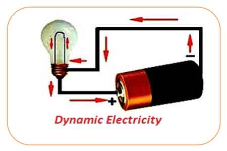
Dynamic electricity is the continuous flow of electric charge—electric current—through a conductor, typically driven by a voltage source. Think of it like water flowing in a pipe, where electrons move uniformly to carry energy.


What is Dynamic Electricity?

Dynamic electricity refers to the continuous movement of electric charges, commonly known as electric current.

  • Describes the flow of electrons or electric charge through a conductor

  • Facilitates energy transfer, enabling devices and machines to operate

  • Used in powering household appliances, industrial processes, lighting, and electronics

It is the continuous flow of electric charges through a conductor, commonly referred to as electric current. Think of it like water flowing through a pipe: voltage acts as water pressure, current as the flow of water, and resistance as the size of the pipe. This motion of electrons is what powers devices, lights homes, and drives entire industries.

Unlike static electricity, which involves charges at rest, dynamic electricity is defined by the constant movement of charge carriers, making it the foundation of modern electrical systems. To understand how voltage, current, and resistance interact in circuits, see our detailed guide on Ohm’s Law.

It depends on the movement of charges through conductive materials. Learn more about the difference between conductors and electrical insulators.

Dynamic electricity is closely tied to the concept of electrical energy, which is produced when an energy source creates movement between charges. A negative charge is naturally drawn toward a positively charged region, and objects with opposite charges will attract one another. This interaction between positive and negative charges is the foundation of current flow. Every type of electrical system, from simple batteries to complex power grids, relies on this basic principle to generate and transfer usable energy.


How It Works (Voltage, Current, Ohm’s Law)

Dynamic electricity occurs when a voltage difference is applied across a conductor, such as copper or aluminum wire. This creates an energy imbalance that causes electrons to flow from one end to the other.

  • Electrons drift slowly, but the electrical effect travels nearly at the speed of light, allowing instant energy transfer.

  • The flow of current is governed by Ohm’s Law: V = IR, where voltage (V) equals current (I) times resistance (R).

  • Moving charges generate magnetic fields and produce heat, demonstrating the role of resistance in circuits and enabling the operation of motors, electromagnets, and heating devices.

  • Current is measured in amperes (A), typically using an ammeter or other measurement instruments.

Electric current is measured in amperes, a unit explained in our introduction to electrical current.

The safe handling of flowing charges requires proper electrical grounding techniques to prevent hazards.

Analogy: Imagine marbles in a tube. Push one marble in, and the entire line shifts almost instantly. Similarly, electron movement is slow, but the effect propagates quickly through the entire circuit.


AC vs DC Explained

Type of Current Description Common Uses Advantages
Direct Current (DC) Electrons flow in a single, steady direction Batteries, electronics, solar panels, EVs Stable output, essential for digital devices and storage systems
Alternating Current (AC) Electron flow reverses direction periodically Power grids, appliances, and industrial systems Efficient long-distance transmission, adaptable to transformers


  • Why AC? Its ability to change voltage levels makes it ideal for transmitting energy over long distances with minimal energy loss.
  • Why DC? Critical for low-voltage devices, renewable integration, and battery storage, where stable current is required.

For a deeper look at how alternating current functions in grids, see our overview of alternating current.

Direct current plays a vital role in storage and electronics. Explore its applications on our page on direct current.


Everyday Applications

Dynamic electricity drives nearly every aspect of modern life:

  • Homes: power lighting, appliances, heating, and electronics.

  • Industry: runs motors, automation systems, and manufacturing equipment.

  • Transportation: essential for electric vehicles, rail systems, and aviation technologies.

  • Renewable energy: harnessed by solar panels, wind turbines, and hydroelectric systems, which is then transmitted via power grids over long distances through reliable power transmission systems.

  • Energy storage: stored in batteries to support grid reliability and electric mobility.

  • Communication systems: support telecom networks, internet infrastructure, and data centers.

In renewable energy systems, dynamic electricity is produced and stored for later use. Learn how it relates to energy storage.

The flow of current must be managed carefully in fault conditions. For details, see our guide on fault current calculation.


Safety and Control

Because moving charges create heat, sparks, and electromagnetic fields, electrical circuits are designed with protective devices:

  • Circuit breakers and fuses prevent overheating and fire risks.

  • Insulation and grounding ensure safe handling of conductors.

  • Control systems regulate current flow for efficiency and reliability.

Circuit safety relies on protective systems. Explore our page on electrical protection for more details.


Static vs Dynamic Electricity

Understanding the difference is key:

  • Static

    • Charges accumulate on surfaces.

    • It can cause small shocks or sparks.

    • Temporary and uncontrolled.

  • Dynamic

    • Charges move continuously through conductors.

    • Power devices and grids.

    • Reliable and controllable.


Future Challenges and Developments

The demand for dynamic electricity is expanding as society transitions to net-zero energy systems. Key developments include:

  • Smart grids to balance supply and demand.

  • Advanced energy storage to integrate renewable sources.

  • Global electrification in emerging economies, driving higher usage worldwide.

It will continue to shape technology, transportation, and sustainability goals in the decades ahead.


Frequently Asked Questions


What is the difference between static and dynamic electricity?

Static involves charges at rest, while dynamic is defined by moving charges, producing electric current used to power systems.


Why is it important in daily life?

It powers homes, industries, transport, communication, and renewable energy systems, making it the foundation of modern civilization.


How is it measured?

It is measured in amperes (A), using tools like ammeters to detect the flow of current in a circuit.


Related Articles


Related News

Capacitance in Series

Capacitance in series reduces overall capacitance by summing the reciprocals of each capacitor. This concept is essential in electronics, circuit analysis, and power systems, ensuring proper charge storage, voltage division, and reliable circuit performance.


What is Capacitance in Series?

When capacitors are connected in series, their combined behavior follows specific rules that affect voltage distribution, total capacitance, and charge consistency.

✅ Reduces total capacitance as capacitors share the voltage

✅ Total capacitance is calculated using the reciprocal formula

✅ Charge on each capacitor is equal in a series circuit


In a series circuit, connecting more than one capacitor in series affects how voltage and charge are distributed, directly impacting the total capacitance of the system. Unlike parallel arrangements, a series setup reduces the overall capacitance and requires the use of a reciprocal formula to calculate the correct value. This configuration functions like a voltage divider, where the total voltage is split across each capacitor based on its individual capacitance. While this reduces the system’s ability to store charge, it also controls how voltage is allocated, which is useful in applications where precise energy storage and voltage regulation are needed.

For a clearer technical explanation, see our what is capacitance page, which breaks down how this key property affects circuit design.

When working with individual capacitors in electronic circuits, it is essential to understand their behaviour and effects. For example, in a series arrangement, the positive plate of one capacitor is connected to the negative plate of the next capacitor in line. This unique connection affects the circuit's total equivalent capacitance (C_total), resulting in a total capacitance that is smaller than the smallest individual capacitance (C) present in the series. The total capacitance of capacitors in series is always less than the value of the smallest individual capacitor in the arrangement.

A series circuit is characterized by its linear sequence of components, through which the current flows in a single path. In such circuits, the total voltage is distributed across each component in proportion to its resistance. The overall resistance of a series circuit is equal to the sum of the individual resistances of the connected components. The unit of capacitance, the farad, measures a capacitor’s ability to store electric charge per unit voltage.

When they are connected in series, the total C of the circuit is affected. This is because the positive plate of the capacitors is connected in series to the total C. Each capacitor stores the same charge in this arrangement, and the total voltage is divided across the capacitors in proportion to their C. This characteristic of series-connected capacitors plays a significant role in designing electronic circuits that require specific voltage and charge distribution properties. To fully grasp how capacitors behave in series, it’s important to understand what is a capacitor and how it stores and releases electrical energy.


Capacitors in Series: Formula, Voltage, and Charge Characteristics

Feature Capacitors in Series
Total Capacitance Less than the smallest individual capacitor
Formula 1/Ctotal = 1/C₁ + 1/C₂ + 1/C₃ + ...
Voltage Distribution Voltage divides across capacitors based on capacitance values
Charge on Capacitors Same charge on all capacitors
Use Case Used when reduced overall capacitance is needed in a circuit
Energy Storage Lower total energy storage than a single capacitor with same voltage


Different types of capacitors, such as ceramic or electrolytic, behave differently in series configurations based on their construction and rated voltage.


Formula for Calculation

To accurately calculate the total C of capacitors connected in series, the following formula is employed:

C_total = 1 / (1/C1 + 1/C2 + 1/C3 + ... + 1/Cn)

This formula calculates the inverse of the total C. To find the actual total C, take the inverse of the sum of the inverse individual capacitances. This mathematical process enables the precise determination of the overall capacitance value in a series configuration, which is crucial when designing or analyzing electronic circuits.


Impact of the Smallest Capacitor on Total Capacitance

When several are connected in series, the total C becomes smaller than the smallest individual C. This phenomenon occurs because the capacitor with a smaller capacitance (C) limits the total capacitance (C), acting as a bottleneck for current flow and restricting the total charge stored in the circuit. Understanding this limiting effect is critical when selecting capacitors for a series configuration, as the smallest capacitor will significantly impact the overall performance of the electronic circuit. Engineers must also consider electrical resistance, which affects how current and voltage behave in conjunction with capacitors in mixed-component circuits.


Comparing Capacitors in Parallel and Series Configurations

In contrast to capacitors in series, when capacitors are connected in parallel, the total C is the sum of the individual capacitances. This difference occurs because each capacitor is directly connected to the power source in a parallel circuit, allowing it to store its charge independently. Consequently, capacitors in parallel configurations offer higher overall capacitance values, making them suitable for applications that require increased charge storage capabilities. Reviewing electrical resistance definition can help clarify how resistance and C work together in impedance-sensitive designs. You can explore how capacitance in parallel differs from series configurations when designing circuits requiring larger energy storage.


Equivalent Capacitance and Voltage Drop in Series Capacitors

The equivalent C of capacitors connected in series can be determined by dividing the total charge stored in the circuit by the total voltage across the circuit. This is because the total charge stored in the circuit equals the sum of the charges on each capacitor. In contrast, the total voltage is calculated to determine the total capacitance for the number of capacitors connected.

The voltage drop in capacitors connected in series is divided among the capacitors in proportion to their C. This means that the voltage across each capacitor is proportional to its C. Understanding the voltage drop distribution in series capacitors is essential when designing circuits that rely on specific voltage levels across components.


Replacing Capacitors in Series with a Single Equivalent Capacitor and Combination Circuits

In some cases, capacitors in series can be replaced with a single equivalent capacitor that has the same C value as the equivalent capacitance of the series capacitors. This replacement technique can simplify circuit design and analysis, consolidating multiple components into a single element with equivalent electrical properties.

In a combination circuit, capacitors are connected in both series and parallel configurations. These complex arrangements are commonly found in practical electronic applications, as they offer more flexibility and adaptability in achieving desired circuit properties. To calculate the total C of a combination circuit, first, compute the capacitance of each series combination, then add those capacitances to find the total C. This process may involve several steps, as the designer needs to consider the contributions of both series and parallel components to the overall C value.


Applications and Considerations of Capacitors in Series

Capacitors in series configurations are utilized in various electronic applications, such as power supply filtering, signal coupling, and decoupling, as well as in tuning and timing circuits. When designing these applications, engineers must consider the capacitors' voltage ratings, tolerances, temperature coefficients, and other parameters to ensure the circuit functions as desired.

One crucial consideration when working with capacitors in series is the voltage rating. The voltage rating of each capacitor must be sufficient to handle the voltage that will be applied across it. Since the total voltage is distributed among the capacitors in series, selecting capacitors with appropriate voltage ratings is essential to prevent component failure or degradation.

Another important consideration is the capacitors' tolerances, which indicate the possible variation in C values from their nominal specifications. Capacitors with tighter tolerances may be required for precise applications, as variations in C values can impact the overall performance of the electronic circuit. 


Related Articles


View more

Electricity Windmill Explained

Electricity windmill converts wind energy into electrical power via rotor blades, generator, gearbox, and inverter, supporting renewable energy, grid integration, power electronics, and efficient electricity production with modern control systems and variable-speed drives.


What Is an Electricity Windmill?

An electricity windmill converts kinetic wind energy into grid-grade electrical power via a wind turbine system.

✅ Generator, gearbox, and rotor optimize energy capture

✅ Inverter and VFD enable grid-quality AC output

✅ SCADA monitors performance, safety, and fault detection


Electricity windmill Mankind been harnessing the wind's energy for many years. From Holland to traditional farms around the world, old style windmills were used in the past for pumping water through primative irrigation systems or used to grind grain. Then, the wind turned large "sails" which were connected by a long vertical shaft that was attached to a grindnig machine or to a wheel that turned and drew water from a well. Today's wind turbine generators can utilize the clean energy of high wind speeds to turn large metal blades which in turn spins a generator that manufactures electric power. For a deeper overview of modern designs, the resource at windmills for electricity explains key configurations used by utilities today.

Electricity windmill turbines, unlike the machines of old, are mounted on very tall towers in order to capture the most wind energy available. At 100 feet (30 meters) or more above ground, wind turbines can take advantage of the faster and less turbulent wind. Turbines catch the wind's energy with their propeller-like blades. Usually, two or three blades are mounted on a shaft to form a rotor. If you're curious how these rotating blades ultimately power homes, see how turbines generate electricity through step-by-step conversion processes.

A blade acts much like an airplane wing. When the wind blows, a pocket of low-pressure air forms on the downwind side of the blade. The low-pressure air pocket then pulls the blade toward it, causing the rotor to turn. This is called lift. The force of the lift is actually much stronger than the wind's force against the front side of the blade, which is called drag. The combination of lift and drag causes the rotor to spin like a propeller, and the turning shaft spins a generator to make power. The rotating shaft must be matched to an electricity generator with appropriate gearing and controls to optimize output.

In recent years, governments have invested enormous amounts of (taxpayer) money in electricity windmill "wind farms" to generate large amounts of energy from large and small wind turbines that take advantage of high winds. These wind systems or energy systems use wind turbine power to create electricity.  Other energy sources like solar power do not produce as much electricity. The only problem with wind generated power is that when the wind stops, so does the generator and therefore the electric power production. Electric power cannot be produced and stored for consumption later. Therefore, wind power can only be counted on mostly when the wind is blowing at optimal speeds and only in locations where the prevailing winds are such that it makes economic sense to build these power plants and this may not be when and where the power is needed. Grid planners track regional electricity production profiles to determine how much wind capacity can be integrated without compromising reliability. As part of a balanced portfolio, policy makers also evaluate alternative electricity options that can complement variable wind resources.

Stand-alone electricity windmill turbines are typically used for water pumping or communications. However, homeowners, farmers, and ranchers in windy areas can also use wind turbines as a way to cut their power bills. For off-grid ranch operations, understanding the interplay between pumps and water electricity systems helps size batteries and controllers correctly.

Small electricity windmill systems also have potential as distributed energy resources. Distributed energy resources refer to a variety of small, modular power-generating technologies that can be combined to improve the operation of the electric power delivery system. In some regions, small-scale hydroelectricity can serve as a firm companion to wind in distributed portfolios.


Related Articles

View more

Geothermal Electricity Explained

Geothermal electricity delivers renewable baseload power by converting subsurface heat through turbines, generators, ORC binary cycles, and heat exchangers, enabling grid integration, high capacity factor, low emissions, and efficient power plant control systems.


What Is Geothermal Electricity?

Geothermal electricity converts geothermal heat to power using turbines and generators for low-emission baseload.

✅ Uses steam, flash, and binary cycle power plant designs

✅ Employs ORC, heat exchangers, and closed-loop systems

✅ Provides baseload, high capacity factor, and grid stability


Geothermal Electricity is produced through geothermal power plants capturing the thermal energy contained in the Earth. Use of geothermal energy is based thermodynamically on the temperature difference between a mass of subsurface rock and water and a mass of water or air at the Earth's surface. This temperature difference allows production of thermal energy that can be either used directly or converted to mechanical or Geothermal Electricity. For context on broader methods and terminology, see this overview of electricity generation and how heat energy is converted to power.

Commercial exploration and development of Plant Geothermal water generated into Electricity to date have focused on natural geothermal reservoirs—volumes of rock at high temperatures (up to 662°F or 350°C) and with both high porosity (pore space, usually filled with water) and high permeability (ability to transmit fluid). The thermal energy is tapped by drilling wells into the reservoirs. The thermal energy in the rock is transferred by conduction to the fluid, which subsequently flows to the well and then to the Earth's surface where it can be converted into Geothermal Electricity. This well-to-turbine pathway is a fundamental part of electricity production from thermal resources.

There are several types of natural geothermal reservoirs. All the reservoirs developed to date for electrical energy are termed hydrothermal convection systems and are characterized by circulation of meteoric (surface) water to depth. The driving force of the convection systems is gravity, effective because of the density difference between cold, downward-moving, recharge water and heated, upward-moving, thermal water. A hydrothermal convection system can be driven either by an underlying young igneous intrusion or by merely deep circulation of water along faults and fractures. Depending on the physical state of the pore fluid, there are two kinds of hydrothermal convection systems: liquid-dominated, in which all the pores and fractures are filled with liquid water that exists at temperatures well above boiling at atmospheric pressure, owing to the pressure of overlying water; and vapor-dominated, in which the larger pores and fractures are filled with steam. Liquid-dominated reservoirs produce either water or a mixture of water and steam, whereas vapor-dominated reservoirs produce only steam, in most cases superheated. Because water acts as the primary working fluid in most systems, understanding the interplay of water and electricity helps clarify operational safety and design.

These hydrothermal systems are distinct from hydroelectricity produced by river impoundments, even though both ultimately rely on water as a medium.

Although geothermal energy is present everywhere beneath the Earth's surface, its use is possible only when certain conditions are met: (1) The energy must be accessible to drilling, usually at depths of less than 2 mi (3 km) but possibly at depths of 4mi (6–7km) in particularly favorable environments (such as in the northern Gulf of Mexico Basin of the United States). (2) Pending demonstration of the technology and economics for fracturing and producing energy from rock of low permeability, the reservoir porosity and permeability must be sufficiently high to allow production of large quantities of thermal water. (3) Since a major cost in geothermal development is drilling and since costs per meter increase with increasing depth, the shallower the concentration of geothermal energy the better. (4) Geothermal fluids can be transported economically by pipeline on the Earth's surface only a few tens of kilometers, and thus any generating or direct-use facility must be located at or near the geothermal anomaly. When these conditions align, engineered systems can efficiently generate electricity from accessible geothermal gradients.

The use of geothermal energy for Geothermal Electricity has become widespread because of several factors. Countries where geothermal resources are prevalent have desired to develop their own resources in contrast to importing fuel for power generation. In countries where many resource alternatives are available for power generation, including geothermal, geothermal has been a preferred resource because it cannot be transported for sale, and the use of geothermal energy enables fossil fuels to be used for higher and better purposes than power generation. Also, geothermal steam has become an attractive power generation alternative because of environmental benefits and because the unit sizes are small (normally less than 100 MW). Moreover, geothermal plants can be built much more rapidly than plants using fossil fuel and nuclear resources, which, for economic purposes, have to be very large in size. Electrical utility systems are also more reliable if their power sources are not concentrated in a small number of large units. In energy planning, geothermal is often evaluated alongside other forms of alternative electricity to balance portfolios and grid resilience. Many developers also highlight its contribution to green electricity targets thanks to low lifecycle emissions.


Related Articles

View more

Electrical Units Explained

Electrical units measure various aspects of electricity, such as voltage (volts), current (amperes), resistance (ohms), and power (watts). These standard units are crucial in electrical engineering, circuit design, energy monitoring, and ensuring the safe operation of electrical systems.


What are Electrical Units?

Electrical units are standardized measures used to quantify electrical properties in circuits and systems.

✅ Measure voltage, current, resistance, power, and energy

✅ Used in electrical engineering, testing, and design

✅ Support safe and efficient electrical system operations

Electrical units are standardized measurements that describe various aspects of electricity, such as current, voltage, resistance, and power. These units, like amperes for current and volts for voltage, help quantify the behavior and interaction of systems. By understanding electrical units, professionals can assess performance, design circuits, and ensure safety across different applications. These electrical units play a crucial role in the functioning of everything from household appliances to industrial machinery, making them fundamental in engineering and everyday technology.

In common electricity systems, various electrical units of measure, such as magnetic field, are used to describe how electricity flows in the circuit. For example, the unit of resistance is the ohm, while the unit of time is the second. These measurements, often based on SI units, help define the phase angle, which describes the phase difference between current and voltage in AC circuits. Understanding these electrical units is critical for accurately analyzing performance in both residential and industrial applications, ensuring proper function and safety.


Ampere

The ampere is the unit of electric current in the SI, used by both scientists and technologists. Since 1948, the ampere has been defined as the constant current that, if maintained in two straight, parallel conductors of infinite length and negligible circular cross-section, and placed one meter apart in a vacuum, would produce between these conductors a force equal to 2 × 10^7 newtons per meter of length. Named for the 19th-century French physicist André-Marie Ampere, it represents a flow of one coulomb of electricity per second. A flow of one ampere is produced in a resistance of one ohm by a potential difference of one volt. The ampere is the standard unit of electric current, playing a central role in the flow of electricity through electrical circuits.


Coulomb

The coulomb is the unit of electric charge in the metre-kilogram—second-ampere system, the basis of the SI system of physical electrical units. The coulomb is defined as the quantity of electricity transported in one second by a current of one ampere. Named for the I8th—I9th-century French physicist.


Electron Volt

A unit of energy commonly used in atomic and nuclear physics, the electron volt is equal to the energy gained by an electron (a charged particle carrying one unit of electronic charge when the potential at the electron increases by one volt. The electron volt equals 1.602 x IO2 erg. The abbreviation MeV indicates 10 to the 6th (1,000,000) electron volts, and GeV, 10 to the 9th (1,000,000,000). For those managing voltage drop in long circuits, we provide a helpful voltage drop calculator and related formulas to ensure system efficiency.


Faraday

The Faraday (also known as the Faraday constant) is used in the study of electrochemical reactions and represents the amount of electric charge that liberates one gram equivalent of any ion from an electrolytic solution. It was named in honour of the 19th-century English scientist Michael Faraday and equals 6.02214179 × 10^23 coulombs, or 1.60217662 × 10^-19 electrons.


Henry

The henry is a unit of either self-inductance or mutual inductance, abbreviated h (or hy), and named for the American physicist Joseph Henry. One henry is the value of self-inductance in a closed circuit or coil in which one volt is produced by a variation of the inducing current of one ampere per second. One henry is also the value of the mutual inductance of two coils arranged such that an electromotive force of one volt is induced in one if the current in the other is changing at a rate of one ampere per second.


Ohm

The unit of resistance in the metre-kilogram-second system is the ohm, named in honour of the 19th-century German physicist Georg Simon Ohm. It is equal to the resistance of a circuit in which a potential difference of one volt produces a current of one ampere (1 ohm = 1 V/A); or, the resistance in which one watt of power is dissipated when one ampere flows through it. Ohm's law states that resistance equals the ratio of the potential difference to current, and the ohm, volt, and ampere are the respective fundamental electrical units used universally for expressing quantities. Impedance, the apparent resistance to an alternating current, and reactance, the part of impedance resulting from capacitance or inductance, are circuit characteristics that are measured in ohms. The acoustic ohm and the mechanical ohm are analogous units sometimes used in the study of acoustic and mechanical systems, respectively. Resistance, measured in ohms, determines how much a circuit resists current, as explained in our page on Ohm’s Law.


Siemens

The siemens (S) is the unit of conductance. In the case of direct current (DC), the conductance in siemens is the reciprocal of the resistance in ohms (S = amperes per volt); in the case of alternating current (AC), it is the reciprocal of the impedance in ohms. A former term for the reciprocal of the ohm is the mho (ohm spelled backward). It is disputed whether Siemens was named after the German-born engineer-inventor Sir William Siemens(1823-83) or his brother, the engineer Werner von Siemens (1816-92).


Volt

The unit of electrical potential, potential difference, and electromotive force in the metre—kilogram—second system (SI) is the volt; it is equal to the difference in potential between two points in a conductor carrying one ampere of current when the power dissipated between the points is one watt. An equivalent is the potential difference across a resistance of one ohm when one ampere of current flows through it. The volt is named in honour of the I8th—I9th-century Italian physicist Alessandro Volta. Ohm's law defines these electrical units, where resistance equals the ratio of potential to current, and the respective units of ohm, volt, and ampere are used universally for expressing electrical quantities. Energy consumption is measured in kWh, or kilowatt-hours. Explore how devices like ammeters and voltmeters are used to measure current and voltage across components. To better understand how voltage is measured and expressed in volts, see our guide on what is voltage.


Watt

The watt is the unit of power in the SI equal to one joule of work performed per second, or to 1/746 horsepower. An equivalent is the power dissipated in a conductor carrying one ampere of current between points at a one-volt potential difference. It is named in honour of James Watt, British engineer and inventor. One thousand watts equals one kilowatt. Most electrical devices are rated in watts. Learn how a watt defines power in electrical systems and its relationship to volts and amperes through Watts' Law.


Weber

The weber is the unit of magnetic flux in the SI, defined as the amount of flux that, linking a circuit of one turn (one loop of wire), produces in it an electromotive force of one volt as the flux is reduced to zero at a uniform rate in one second. It was named in honour of the 19th-century German physicist Wilhelm Eduard Weber and equals 10 to the 8th maxwells, the unit used in the centimetre—gram—second system.

Related Articles


View more

Direct Current Explained

Direct current (DC) is a steady flow of electric charge in one direction, widely used in batteries, electronics, and power supply systems. Unlike alternating current, it provides constant voltage, making it vital for circuits, devices, and renewable energy applications.


What is Direct Current?

Direct current (DC) is an electric charge that flows consistently in one direction through a conductor.

✅ Provides constant voltage for stable operation

✅ Powers batteries, electronics, and renewable systems

✅ Differs from alternating current by unidirectional flow

Direct current (DC) plays an essential role in electrical power. It is a type of electrical flow where the flow of electric charge remains constant and does not change direction. DC differs from alternating current (AC), periodically reversing direction as the voltages and amperage vary with time. Direct current is often compared with alternating current, which reverses direction periodically and dominates modern transmission systems.

One of the most well-known proponents of direct current was Thomas Edison, who competed with George Westinghouse, an advocate for alternating current, in the late 19th century. Their competition, known as the "War of the Currents," ultimately led to the widespread adoption of AC systems, which are more suitable for long-distance, high-voltage transmission. However, this does not diminish the importance and numerous applications of direct current in modern technology. To better understand how DC works, it helps to review basic electricity concepts such as charge, voltage, and resistance.

A direct current power supply, often found in electronic devices, converts AC power from the power grid into DC power. This conversion process ensures a constant voltage that meets the device's requirements. The conversion is achieved through transformers, rectifiers, and capacitors, which stabilize the voltage and smooth out the electrical signal.

Direct current has various advantages and disadvantages. One of its main advantages is the ability to provide stable, constant power, essential for devices such as computers, smartphones, and other sensitive electronics. Additionally, DC power has lower losses in the form of heat dissipation compared to AC power. On the other hand, a significant disadvantage of DC is its limited capacity for long-distance power transmission. It requires larger conductors to maintain efficiency, and the power loss becomes substantial over long distances. The difference between AC and DC has shaped the history of electricity since the “War of the Currents” between Edison and Westinghouse.

DC motors and generators operate through the principle of electromagnetism. A DC motor converts electrical energy into mechanical energy, while a generator turns mechanical energy into electrical energy. The interaction between a magnetic field and the flow of amperage within conductive wires generates a force, causing the motor's rotor to rotate. In the case of a generator, the mechanical motion induces a flow within the conductive wires.

Battery technology heavily relies on direct current, as batteries store and discharge energy in DC power. This is one reason electric vehicles (EVs) use DC motors and batteries for propulsion. In addition, the growing trend towards renewable energy sources, such as solar panels and wind turbines, further highlights the importance of DC power, as these sources initially generate DC power before converting it to AC for grid integration. For a broader context, you can explore electricity fundamentals, which cover both direct and alternating current and their applications.

Both AC and DC currents can be converted and transmitted through specialized equipment. For example, AC can be converted into DC using rectifiers, while DC can be converted back into AC through inverters. The conversion between these two forms of electricity enables the integration of renewable energy sources into the existing power grid. Additionally, it enables the efficient use of energy storage systems, such as batteries. Many renewable energy systems generate DC first, making them a form of alternative electricity that is later converted to AC for grid use.

DC voltage conversion involves changing the voltage level of a direct current without altering its form. This is typically achieved through DC converters, which either step up (increase) or step down (decrease) the voltage. In many electronic devices, DC converters provide the correct voltage levels required for different components to function optimally.

Direct current can be calculated using Ohm's Law, which states that voltage (V) equals the product of flow (I) and resistance (R). The formula is V = I × R. This fundamental principle is crucial for understanding and analyzing electrical circuits, including those involving direct current.

DC is directly related to electrical resistance, since Ohm’s Law determines how voltage, cpnduction, and resistance interact in a circuit.

Devices like rectifiers and inverters rely on principles explained in Ampere’s Law and Biot-Savart Law, which describe the relationship between electricity and magnetism.


Frequently Asked Questions


What is the best formula to calculate DC electrical stream? 

Ohm's Law is the fundamental principle governing the relationship between voltage, flow, and resistance in an electrical circuit. It is named after German physicist Georg Simon Ohm, who formulated the law in the early 19th century. Ohm's Law can be used to calculate direct (DC) electrical current when the voltage and resistance are known.

The formula for Ohm's Law is:

V = I × R

Where:
V = Voltage (volts)
I = Current (amperes or amps)
R = Resistance (ohms)

This formula can be rearranged to calculate the current (I) when voltage (V) and resistance (R) are given:

I = V / R

Using this formula, we can determine the DC electrical energy flowing through a circuit when the voltage across the circuit and the resistance of the circuit are known.

For example, consider a simple DC circuit with a 12-volt voltage source and a 6-ohm resistor. Using the formula for calculating current, we can determine the amperage flowing through the circuit:

I = V / R
I = 12 V / 6 Ω
I = 2 A

Thus, the DC electrical amperage flowing through the circuit is 2 amperes.

To calculate DC electrical stream, apply Ohm's Law by dividing the voltage (V) by the resistance (R) to determine the current (I) in amperes. Ohm's Law is a fundamental principle in electrical engineering, serving as the basis for understanding and analyzing electrical circuits, including those involving direct current.


Are there fewer losses with the direct current than with the alternating current?

Whether there are fewer losses with direct current (DC) than alternating current (AC) depends on the specific application and context. In certain scenarios, DC can have fewer losses, while AC might be more efficient in others. Below are some examples to illustrate this point:

Transmission losses: In long-distance high-voltage power transmission, direct high-voltage current (HVDC) transmission lines can have fewer losses than traditional AC transmission lines. This is because DC transmission lines do not suffer from reactive power losses or the skin effect (which causes higher resistance in AC lines due to the stream flowing mainly on the conductor's surface). Moreover, HVDC lines can be more efficient over long distances as they require only two conductors, while three are needed for AC transmission lines.

Electronic devices: When it comes to electronic devices like computers and smartphones, as well as other sensitive equipment, DC power is often preferred because it provides stable, constant power, resulting in lower losses in the form of heat dissipation. However, these devices need a conversion from the AC power supplied by the grid to the DC power they require. The conversion process may introduce some losses, but DC can be more efficient for these applications once the power is converted.

Electric power transmission over short distances: AC is typically more efficient than DC for shorter distances and lower voltage levels. AC voltage can be easily transformed to different levels using transformers, which are relatively simple and low-loss devices. In contrast, converting DC voltage levels requires more complex and potentially lossy power electronic converters.

The efficiency of direct and alternating currents depends on the specific application and context. For example, DC power can have fewer losses in some cases, such as HVDC transmission lines and sensitive electronic devices. On the other hand, AC is more efficient for short-distance and lower voltage-level transmission, mainly due to the ease of transforming voltage levels using transformers.


Is direct current safer than alternating current?

The safety of direct current (DC) and alternating current (AC) depends on several factors, including voltage, stream levels, and the specific application. However, it is essential to remember that both types of current can be hazardous under specific conditions.

Both charge flow types are generally considered safe when comparing the safety of DC and AC at low voltages and amps. However, some differences in the physiological effects of DC and AC on the human body can make one type of amperage more hazardous than the other under certain conditions:

Muscle contraction: AC can cause muscle contractions that may make it difficult for a person to release a live wire or conductor. In contrast, DC can also cause muscle contractions, but typically only when making or breaking contact with the conductor. This means that once a person is in contact with a DC source, the muscles may not contract continuously, making it easier to let go.

Ventricular fibrillation: AC has a higher probability of causing ventricular fibrillation (a life-threatening heart rhythm disturbance) than DC at the same energy levels. The frequency of AC power, typically 50 or 60 Hz, can interfere with the electrical signals in the heart, leading to this dangerous condition. DC is less likely to cause ventricular fibrillation because it lacks a frequency component.

Skin resistance: Human skin has a higher resistance to DC than to AC, which can result in less amperage flowing through the body when exposed to DC compared to AC at the same voltage levels. However, this difference in resistance is mostly relevant at low voltages, and the risk of injury still exists when dealing with high-voltage DC sources.

Although there are some differences in the effects of DC and AC on the human body, it is essential to understand that both types of amperage can be dangerous when not handled properly. Therefore, safety precautions must always be taken when working with electrical systems, whether they involve direct or alternating current.

Ultimately, the safety of direct and alternating currents depends on the specific situation and proper handling of electrical systems. However, by following established safety protocols, potential risks associated with both types of amperage can be minimized.


Related Articles


View more

Ohm's Law Formula

The Ohm's Law formula is a cornerstone of electrical engineering, serving as a basis for analyzing and designing electric circuits. Its applications range from determining the appropriate values of electrical components to predicting the behaviour of complex systems. By exploring the relationship between voltage, current, and resistance and their connections with other fundamental laws in electromagnetism, we can gain a deeper understanding of the principles that govern the flow of electricity and its conversion into other forms of energy.

Ohm's Law states that the relationship between voltage, current, and resistance. This law, named after its discoverer Georg Simon Ohm, has wide-ranging applications in various fields, from the design of simple electrical circuits to complex electronic systems.

Ohm's Law, denoted as V=IR, dictates that the voltage (V) across a conductor between two points is directly proportional to the current (I) flowing through it, as long as the resistance (R) of the material remains constant. This equation lays the foundation for understanding electric circuits, and its relevance extends to both alternating current (AC) and direct current (DC) systems.

Let's consider a simple scenario to implement Ohm's Law. In an electrical circuit, a battery supplies voltage (also called electric potential or electromotive force), which causes electrons to flow, generating an electric current. The flow of these electrons encounters resistance due to the physical properties of the materials used in the circuit. The higher the resistance, the more the material opposes the flow of electrons, leading to a decrease in the electric current.

A practical application of Ohm's Law calculator can be found in determining a resistor's suitable value for a circuit. Using the formula V=IR, you can calculate the required resistance by rearranging the equation as R=V/I, where you substitute the known voltage and current values to find the unknown resistance.

When it comes to units, voltage is measured in volts (V), current in amperes (A), and resistance in ohms (Ω). It is essential to be mindful of these units when working with electrical components, as they determine the overall performance and safety of the system.

While Ohm's Law plays a critical role in understanding electric circuits, it is also interconnected with the concept of conductivity. Conductivity, a measure of a material's ability to conduct electrical energy, is the reciprocal of resistance. The more conductive a material is, the less resistance it exhibits, and vice versa. Conductivity helps engineers and designers select the right materials for specific applications, ensuring the efficiency and reliability of electrical systems.

However, Ohm's Law has its limitations. In real-world scenarios, resistance may not remain constant for all materials and under all conditions. Factors such as temperature, pressure, and the material's non-linear behaviour can cause deviations from the ideal behaviour predicted by Ohm's Law. As a result, this law is considered an ideal approximation for most practical purposes but may not be universally applicable.

Ohm's Law is also related to other fundamental laws in electromagnetism, such as Faraday's, Lenz's, and Biot-Savart's law. Faraday's Law describes the induction of voltage in a conductor moving through a magnetic field, while Lenz's Law explains the direction of the induced current due to this magnetic field. The Biot-Savart Law, on the other hand, calculates the magnetic field generated by an electric current. Understanding these laws is vital for grasping more complex concepts and phenomena in electromagnetism and their practical applications.


How to use Ohm's Law Equation

Let's consider an example of how to use Ohm's Law in a practical situation.

Suppose you have a 12-volt (V) battery connected to a simple electrical circuit with a single resistor. The current flowing through the resistor is measured to be 2 amperes (A). You can use Ohm's Law to calculate the resistance of the resistor in the circuit.

Recall the Ohm's Law formula: V = IR, where V is voltage, I is current, and R is resistance.

In this example, we know the voltage (V = 12 V) and the current (I = 2 A), and we want to find the resistance (R).

Rearrange the formula to solve for resistance: R = V / I

Now, substitute the known values into the formula:

R = 12 V / 2 A

R = 6 ohms (Ω)

So, the resistance of the resistor in this circuit is 6 ohms. By using Ohm's Law, you can determine unknown values in a circuit, such as resistance, as long as you have the other two known values (voltage and current).

View more

Sign Up for Electricity Forum’s Newsletter

Stay informed with our FREE Newsletter — get the latest news, breakthrough technologies, and expert insights, delivered straight to your inbox.

Electricity Today T&D Magazine Subscribe for FREE

Stay informed with the latest T&D policies and technologies.
  • Timely insights from industry experts
  • Practical solutions T&D engineers
  • Free access to every issue

Live Online & In-person Group Training

Advantages To Instructor-Led Training – Instructor-Led Course, Customized Training, Multiple Locations, Economical, CEU Credits, Course Discounts.

Request For Quotation

Whether you would prefer Live Online or In-Person instruction, our electrical training courses can be tailored to meet your company's specific requirements and delivered to your employees in one location or at various locations.